


Reducing LP drum pressure increases cold-weather output
Best of the Best Award
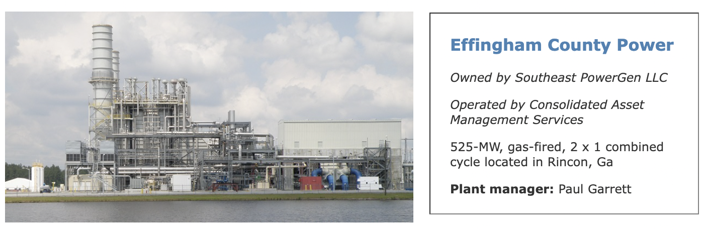
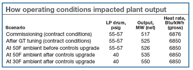
Challenge. Effingham County Power’s 2 x 1 F-class combined cycle had lower-than-expected cold-weather electric production because of condensate-system restrictions. The Southeast PowerGen facility, operated by Consolidated Asset Management Services, initially was limited to 517 MW, with a heat rate of 6876 Btu/kWh at ISO conditions, before a gas-turbine (GT) controls upgrade with GE OpFlex increased total plant generation by approximately 9 MW.
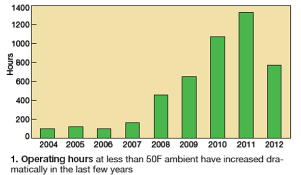
The winter following that upgrade, plant staff determined cold-weather performance was limited by the condensate system. Specifically, above 50F ambient, plant electric production was constrained by GT output, below 50F by the condensate system’s ability to supply a sufficient amount of water to the LP steam drums (Fig 1).
However, when planning the addition of inlet chillers to increase GT output, plant personnel noticed that the condensate-system limitation would affect operations over more run time because of a planned change in the winter operating profile from cycling to base load. Initial action involved evaluating the cost of upgrading the condensate system to boost its capacity.The HRSG’s LP preheater bypass originally was programmed for a set point of 75 psig to protect against cold-end corrosion. Actual LP drum pressures at base load were 55-57 psig, so the LP preheater bypass valves typically remained closed during plant operation. Above 526 MW, the condensate system was unable to maintain the desired LP-drum water levels—even with all three 50% condensate pumps in operation. This only limited output during winter operations because of the plant’s warm geographical location.
Solution. Effingham staff discussed various alternatives and believed condensate return flow could be increased, without capital expenditure, by lowering LP drum pressure. Plant technicians experimented over a period of several days by operating the LP preheater bypass manually to reduce LP drum pressure. By comparing condensate flow versus LP drum-level control valve position at various drum pressures, they verified that condensate return flow rates could be increased. For the lower LP-drum pressures, condensate-pump operating conditions were within the allowable pump curves, and adequate NPSH was verified for the boiler feed pumps.
 Results. Using LP preheater bypass valves to lower LP drum pressure to 40 psig, plant output at 50F ambient was increased from 526 to 535 MW. At 30F, production could be increased to 545 MW with only two of the three condensate pumps running; with all three in operation, 550 MW was possible (table). Providing new logic for the automatic operation of LP-preheater bypass valves gives operators multiple options by simply changing the pressure set point. This operating change had a negligible impact on plant heat rate and was done at essentially no cost.
Project participants:
Richard Blankenship & Don Johnson
Equipment supports core-skills training, proficiency
Best of the Best Award
Effingham County Power relies on multi-skilled GT technicians to operate the plant. Their core skills are electrical, I&C, and mechanical. Skills training consists of a series of computer-based lessons and exams divided into modules. After each module is completed, the technician performs the practical job tasks assigned. When all the modules have been completed, a series of so-called job performance measures (JPMs) are completed as a final evaluation. The company’s training coordinators developed the JPMs for each core skill to ensure consistent minimum standards among all technicians throughout the company’s facilities.
Challenge. The company’s overall challenge was to safely and effectively train all operators without affecting plant availability. This was difficult for several reasons, including these:
• A goal of the training program is to have technicians perform hands-on training and evaluations rather than simulated tasks. However, opportunities to train on actual equipment were limited because of the plant’s operating schedule. Plus, the program was designed to allow qualified technicians to practice their skills to maintain proficiency whenever their schedules permitted.
• The training program is arranged to evaluate the ability of technicians to troubleshoot equipment faults and determine their root cause. In testing the technician’s hands-on knowledge, training coordinators found it difficult to insert anomalies.
• Technicians are required to set up switches and transmitters for a specific application. Testing on installed switches and transmitters, which already are set up to perform a specific function, made it difficult to thoroughly evaluate an individual’s skills.
• For some of the job tasks, the technician only used the acquired skills on an annual basis—for example, hanging high-voltage grounds and inspecting dc motor brushes. Training on, and evaluation of, these skills was difficult because it required placing a clearance on systems that made the plant unavailable for dispatch.
Solution. Project goal was to gain access to equipment conducive to realistic training and to incorporate as many of the JPMs as possible. The first action taken was to contact a local technical college that offered electrical, mechanical, and I&C degree programs. While the labs and training facilities met expectations, employee work schedules and travel distances made this option infeasible.
Next, several companies that supply training labs to colleges and industrial companies were contacted. The high cost of equipment nixed this option. An alternative was to contact various vendors for quotes on powerplant equipment suitable for the training planned. Suppliers were told the equipment did not have to be operational because the use was disassembly/reassembly training. However, no castoffs were available; new equipment would have to be purchased at cost. Budgetary considerations would severely restrict the amount of equipment that could be purchased.
The decision made was to construct a training-lab bench in-house to minimize program cost. The project started by collecting switches and transmitters throughout the plant that were not operating correctly. Pumps and valves that had been removed from service also were gathered up. Several salvage companies and equipment dealers with Internet sites were contacted when searching for a specific item. Prior to purchase, prices were compared to those available from an authorized vendor. In all cases, there was a significant cost savings when purchasing online.
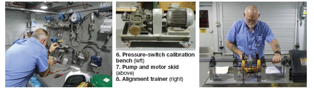
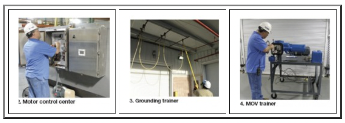
One of the simplest trainers constructed is used to evaluate a technician’s ability to hang grounds on high-voltage conductors (Fig 3). Three sections of conduit are mounted on the overhead of the back porch alongside the training area with a section of grounding cable. This set-up allows trainees to practice handing grounds using a hot stick and arc-flash clothing without affecting plant operation. The grounding trainer has been used for initial training, as well as for refreshing an individual’s skills prior to hanging grounds for a plant-wide outage.Construction of equipment stands followed. Because the company’s plants do not have dedicated training areas, the equipment stands were made mobile to facilitate movement. Several of the training stands are shown in Figs 2-8. This equipment can support training on numerous JPMs. For example, the electrical trainer in Fig 2 is designed to test an employee’s skills in troubleshooting a faulty breaker to the component level, as well as testing skills in measuring a motor’s electrical performance.
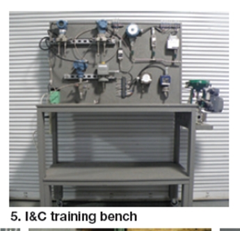
The I&C training bench has several transmitters and switches installed (Fig 5), providing an opportunity to improve multiple individual skills at one location. It also has a low-voltage power supply so the transmitters operate the same as if they were in the field.
Results. of this project were immediate. Trainees are able to practice their skills at any time without affecting plant operation. In addition, they can come into work, outside of their normal shift schedule, to hone skills. Subject-matter experts are available for assistance when needed. The program also is paying dividends by enabling qualified employees to maintain their proficiencies.
Project participants:
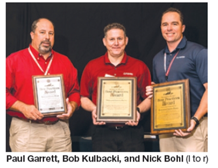
Nick Bohl, production manager
Bob Kulbacki, production team leader
Bill Beahm
Cheryl Hamilton
Alan Sparks
Sean O’Neill
Arc flash data sheets, labels create a user-friendly program
Best Practices Award
In 2011, an outside contractor performed a “Short-Circuit, Protective-Device Coordination and Arc Flash Study” that included placing arc-flash data/summary labels on all surveyed equipment. The equipment and labels are located throughout the plant.
Challenge. Conducting a proper pre-job brief involving energized electrical equipment was difficult without the shock hazard, shock boundaries, and proper personal protective equipment (PPE) information readily available. Data had to be retrieved from the affected equipment in the plant and then used to conduct the pre-job brief. Personnel observing maintenance activities could not verify that the proper controls were being used without having to review the data on the posted arc-flash labels.
In addition, the plant only had two sets of arc-flash PPE, both rated at 65 cal/cm2, and two sets of Class 1 electrical gloves. This PPE was used for all work on energized electrical equipment. This was difficult when the technician was required to perform maintenance on small components with the bulky Class 1 gloves and could potentially cause heat stress because of the high temperatures and humidity.
The outside contractor provided onsite training for all plant personnel. The training consisted of arc-flash terms, definitions, and how to work on energized electrical equipment in accordance with NFPA 70E.
Solution. The plant’s arc-flash safety program had to be revised—not only to update the plant’s existing procedures, but also ensure that equipment hazards, shock boundaries, and personal protective equipment data were available in a centralized location, supporting proper safety review prior to working on energized electrical equipment.
Step 1: Gather all the hazard, shock, and PPE requirements from the equipment survey. This information was then used to create a spreadsheet listing all of the plant’s equipment and a data sheet for each individual component (Fig 9). The spreadsheet contains the basic arc flash data for all the equipment to be used as a quick reference.
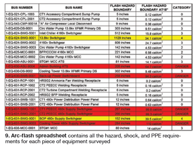
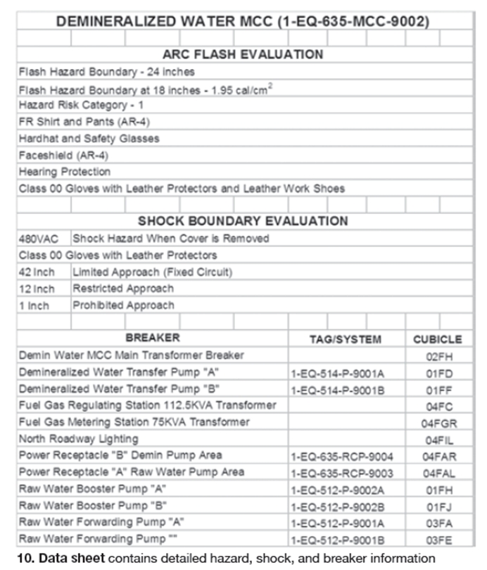
The plant’s arc-flash safety program was revised to incorporate the latest NFPA 70E requirements for working on energized equipment and useddata from the plant’s arc-flash study. A new arc-flash safety checklist was created for use while conducting the pre-job brief for working on energized equipment. The terminology found on the labels and data sheets was employed in the new checklist to ensure accurate hazard evaluation. The data sheets contain the detailed arc-flash evaluation information, shock-boundary evaluation data, and all breakers located on this equipment (Fig 10). The spreadsheet and data sheets are placed in a binder maintained in the control room segregated by voltages. This helps in locating equipment data sheets quickly for required maintenance.
Step 2: Determine the appropriate PPE levels for the hazard categories identified within the plant. There were several requirements considered when purchasing the PPE. They included which hazard-risk categories could be covered by the same PPE levels. It was determined that common sizes could be used by the majority of the technicians to perform work.
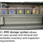
Two sets of PPE were purchased for Hazard Categories 0, 2, 3, and 4. Hazard Category 2 PPEs are used for Hazard Category 1 work, because they have similar requirements. These PPEs were placed in individual bins for easy storage and retrieval when needed, and to facilitate monthly inventory and inspection requirements (Fig 11). All the PPE is stored in a centralized climate controlled room, with all personnel having access.
Four sets of Class 00 and two sets of Class 2 electrical gloves were purchased for use by plant personnel while performing electrical work. The reasoning behind just two categories is that the Class 2 affords the highest protection for the technician when opening air disconnects and performing the live-dead-live test prior to hanging equipment grounds.
In addition, Class 00 gloves give the technician the manual dexterity to work on small items of energized electrical equipment. Plant personnel are not trained to work on electrical equipment rated more than 480 V, so higher-class electrical gloves are not required.
Multiple sets of gloves were purchased so that more than one job involving energized electrical equipment could be performed at the same time. Also, this allows gloves to be sent off to the Testing Laboratory as required, while keeping an inventory on site to perform maintenance as needed.
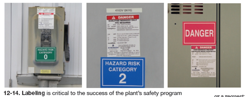
Step 3: Design and purchase 3 x 5-in. hazard-risk category labels to place on the affected equipment; this enables personnel to see the category of equipment being worked on from a distance. Hazard Categories 0, 2, 3, and 4 and danger labels were purchased and placed on the equipment corresponding to the hazard category evaluated by the arc-flash study. These labels are located near the arc-flash data labels to assist the technician.
Labels were also placed on bins for the associated hazard-category PPE. This was done to help the technician verify the correct PPE for the equipment they were assigned to work on when approaching it.
Final step: Conduct arc-flash safety training for all plant personnel. This was conducted during several of the plant’s monthly safety meetings as the various phases of the program were completed. The first month’s training was on the new procedure and the data sheets that were created in the control-room binder. Prior to the next meeting, the plant received the new arc-flash PPE and training was provided on use and proper care. After all the hazard-risk category labels were in place, and the designated PPE storage area assigned, the final phase of the training was conducted.
Since the new arc-flash safety program was being used throughout the training phase, feedback was welcomed from the technicians who had performed work on energized electrical equipment. This feedback was then evaluated and changes to the program were implemented, if deemed necessary.
Results. Prior to the changes in the plant’s arc-flash safety program, it would take several minutes for the data from the posted labels to be retrieved to conduct a pre-job brief, increasing turnaround time. Also, when planning to work on energized electrical equipment, the technician did not know the level of PPE required until reviewing the posted arc-flash safety labels. With the information located in the control room, it is reviewed quickly and equipment down time is minimized.
With the new PPE onsite, technician comfort has improved substantially—especially when working in the heat of the day. The hazard segregation and storage design of the PPE allows quick retrieval in the event of an emergency. With the new class 00 electrical gloves, the safety of the technician has been improved when working on small breaker parts.
In addition, during the pre-job briefs, we can inspect any outside contractor’s PPE to ensure they meet the plant’s arc-flash safety program requirements. This inspection can be performed prior to them entering the plant, thus minimizing work stoppages and safety near misses.
The new hazard-risk category labels make all personnel aware of risks when monitoring work on energized electrical equipment. It also helps technicians verify whether they have the proper PPE prior to starting work.
Project participants:
Nick Bohl, production manager
Bob Kulbacki, production team leader
Better organization of paperwork in the control room pays dividends
Challenge. The large number of permits, clearances, and preventive-maintenance work orders generated at Effingham County Power demanded better organization to ensure accurate accountability in the control room. In the past, several binders were maintained for hot-work, confined-space, and lock-out/tag-out (Loto) programs.
The company’s procedures require hot-work and confined-space permits to be posted at the jobsites for personnel to review prior to and during maintenance. Copies of these active permits were maintained in the program’s binder in the control room. Once work was complete, and the permits no longer required, they were closed out by removing them from the program folder and placed into a designated “closed” folder.
 All of the facility’s active PM work orders were kept in a single pocket wall file inside the control room. It included all the weekly, monthly, quarterly, semi-annual, and annual PMs scheduled. Having all the PMs in the same wall file, ensuring preventive maintenance was being performed on time was difficult. There were many occasions where a weekly PM would be missed because of this process. Loto paperwork also was maintained in a binder in the control room. This paperwork had to be removed from the binder anytime a Loto change was necessary, an employee or contractor had to be signed off or onto the Loto, or a request to walk down the Loto was made. But because all clearances were retained in the same binder, retrieval of these forms became time consuming and cumbersome, especially during outages. Plus, the forms often were damaged by constant removal from the three-ring binders.
This overall system of organization not only made dealing with permits and PMs difficult, it also required the use of six different binders which took up a large amount of space inside the control room.
Solution. The need for better organization was a must, along with wanting to reduce the number of binders in the control room. Plant personnel decided that the best way to organize paperwork and utilize less space was to install multiple pocket wall files in the control room (Fig 15).
The first step was to determine the number of pocket wall files required and the best location for easy access and visibility. The PMs were separated by weekly, monthly, quarterly, semi-annual and annual periodicities. This would allow the control room operator (CRO) and team lead to determine if any PMs were required for completion during their shift, when they came on duty. With PMs separated by periodicity, managers could quickly determine if PMs were overdue without sorting through all the work orders. An empty wall pocket meant there were no PMs due for that period.
The safety program pocket wall files were mounted directly in the control room for visibility and easy access. Both the hot-work and confined-space programs were assigned two pocket wall files. One labeled active and the other inactive. The active pocket wall file contains blank permit forms and an index listing permit location, plus establishment and closure dates. All closed permits were placed in the inactive pocket wall file for final review by designated personnel.
The Loto program was assigned five pocket wall files; combustion turbine 1, combustion turbine 2, steam turbine, balance of plant, and inactive. Active clearances were placed into the appropriate pocket wall file for the assigned unit. Forms were retrieved as needed for review and when workers were required to sign onto and off of the clearances. When clearances were closed they were placed in the inactive pocket wall file awaiting final review. Once the final review is complete, the clearance is filed per plant procedure.
Results. Immediate results noticed were having the active permits, clearances, and PMs readily available. The CRO and team lead were able to see forms easily and determine which PMs required completion on their shift.
During high maintenance periods, several clearances were retrieved at a time by personnel, increasing process efficiency. With all clearances organized by unit they were easily monitored and controlled.
Another benefit of having inactive permits placed in pocket wall files is it enables a quick review and comparison to the program index, to determine if a permit is missing or active. Finally, the number of binders maintained in the control room has been reduced, making more efficient use of workspace.
Project participants:
Nick Bohl, production manager
Bob Kulbacki, production team leader