


NV Energy, Xcel Energy, PG&E promote collaboration on air-cooled condensers
The North American electric-power industry’s first air-cooled condenser (ACC) was integrated into the design of Neil Simpson Unit 1, which began commercial operation in 1969. The 18-MW, coal-fired plant in Gillette, Wyo, built by Black Hills Power Inc, Rapid City, SD, helped lay the groundwork for dry cooling in power generation.
 Adoption of dry-cooling technology was slow, even by this industry’s standards. To illustrate: PacifiCorp’s 360-MW Wyodak Generating Station, located about five miles east of Gillette, started up in 1978 with an ACC that remained the largest such unit in the world for more than two decades.
NV Energy’s Chuck Lenzie Generating Station took over the top position in theUSin 2006 with the installation of a 100-cell ACC to reject heat from its two 2 x 1 650-MW combined cycles. Today,Nevada’s leading electric utility is thought to have the industry’s largest investment in dry cooling with more than 250 cells in operation.
Water-use restrictions dictated by soaring population growth in the arid West made dry cooling a necessity for many new generating facilities—most of them gas-fired combined cycles. Dry cooling can reduce by about 90% the amount of water consumed by a typical nuclear or fossil-fired thermal plant.
At first, air-cooled condensers were specified only for generating stations in water-short regions, primarily because they are more expensive to operate than evaporative systems. But with water concerns increasing throughout the country, you can find them almost anywhere today—even inNew York City, where the average annual rainfall is in the neighborhood of 5 ft.
User group organized. In the last 10-15 years, the industry has learned a great deal about the design, operation, and maintenance of these heat exchangers, but there’s a long way to go. Just think for a moment about the vast amount of steel surface that must be protected against corrosion.
Flow-accelerated corrosion (FAC) and consequent iron transport to the condensate/feedwater system provided the incentive for a few of the industry’s top water chemists—among them Xcel Energy’s Dr Andrew Howell and Structural Integrity’s Dr Barry Dooley, formerly with EPRI—to meet informally once or twice a year to discuss problems and possible solutions.
But steam-side issues were not the only concerns of owners. There were problems with gearboxes, fans, air-flow distribution, etc, that also could benefit from group-think. So NV Energy launched the ACC Users Group and hosted the first meeting at itsLas Vegasheadquarters in November 2009.
A steering committee was formed the following year with Howell as the chairman; Dooley also signed on. Steam-side covered, NV Energy’s Dave Rettke and Duke Energy’s Bob Mohr were recruited for their maintenance and design expertise, respectively.

Xcel Energy sponsored the second conference at its Comanche Station in September 2010. That plant’s 750-MW, coal-fired Unit 3, which began commercial operation only a few months before the meeting, features a heat-rejection system with both water- and air-cooled condensers.
Pacific Gas & Electric Co hosted the 2011 meeting last September at its conference center in downtown San Francisco, and conducted a tour of its new Gateway Generating Station—an ACC-equipped 2 x 1 F-class combined cycle. Presentations from the three meetings can be accessed at www.acc-usersgroup.org. The group’s website also offers a discussion forum for ACC owner/operators.
Lessons learned. User groups offer an unequaled opportunity to share information on problems, solutions, lessons learned, best practices, etc, that will increase your professional worth and benefit the plant owner by improving performance and/or reducing costs.
Rettke’s presentation on condition-based maintenance (CBM) and ACC best practices, which stimulated much follow-on discussion inSan Francisco, is a case in point and the subject of this article. Future articles will cover steam-side and general design issues.
By way of background, Rettke, a machinist by trade, is a maintenance mechanic at NV Energy’s Walter M Higgins Generating Station inPrimm,Nev.You can’t miss this plant when driving fromCaliforniatoLas Vegas: It dominates a hill about a mile to the right of Route 15 at the state line.
Rettke began by describing Higgins’ CBM program, which is characteristic of programs at the utility’s other powerplants. Everyone at the station is involved and takes ownership of the plant and its systems. Monthly equipment assessment meetings are of vital importance to the program’s success. At Higgins, critical equipment is divided up into 12 groups. Each month, one group is discussed in detail.
The agenda encompasses maintenance history; safety, operational, and maintenance issues; possible continuous improvements; action items and dates; and individual responsibilities. For Higgins’ 40-cell ACC, the CBM program has contributed the following benefits/improvements, among others:
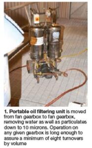
1. The O&M team, directed by Jeff Smith, relies on fluid analysis to guide gearbox oil changes, thereby minimizing the cost of maintenance.Samples are taken semi-annually, before filtering the oil using a portable rig to remove particulates down to 10 microns as well as water (Fig 1).
Each gearbox contains 8 gal of Mobil SHC XMP 320, which has a replacement cost of about $500. Thus changing gearbox oil periodically, as some plants do, would be a major expense. Oil is cycled through the filtering unit at least eight times to assure it is in top condition. Rettke said this regimen has been effective; oil has been replaced in only a couple of gearboxes since the plant went into service early in 2004.
2. Weekly walk-downs by the mechanical staff to inspect both the structure and equipment. Rettke told the group that the inspection routine suggested by the CBM program puts maintenance specialists on the fan deck for visual checks. They are assisted by a PI screen with graphic images of each fan assembly and trended data to help determine where especially close inspection may be required. Many issues have been caught over time, the machinist said, contributing to high operational reliability.
A finding by the inspection team that was puzzling at first, Rettke continued, were bolt heads found periodically on deck plates (Fig 2). Not a big deal until the mechanics realized a couple of plates were down to one retention bolt. No one wanted to have loose deck plates 60 ft above an area with unrestricted personnel access.

The problem, it turned out, was too-tight bolting for a “live” structure. Bear in mind that the ACC structure is almost always in motion because of changes in temperature and wind speed and direction, equipment vibration, etc. Opting for welding over fasteners was ruled out because the O&M staff didn’t want to change the behavior of the structure.
The solution was to drill larger holes in the deck plates—0.375 in. in this case—and secure platform sections with 0.250 in. pan-head bolts threaded into deck support beams. The fender washer shown in Fig 3 allows movement between the deck plate and support beam. Bolts are held in position with Loctite®.

3. Identified a need to monitor vibration and oil pressure remotely. The first was accomplished by installing one accelerometer on the motor and one on the gear reducer for each of the 40 fans. Quality of vibration data is sufficient to warn of an impending problem. A digital gage was installed to monitor oil pressure (Fig 4). All data are transmitted to, and retained in, the plant’s PI historian.
Rettke recalled that shortly after the accelerometers and pressure gages were installed, maintenance personnel “caught” a gear-reducer oil pump failure. To date, the plant maintenance team has identified eight incidents of filter clogging by trending oil pressure as illustrated in Fig 4.
4. Identified the need for a safer method of removing and installing gear reducers.
5. Check fan-blade angle and condition annually. Blade angle is measured at both the hub and blade tip and recorded.
Safe handling of gear reducers
 Rettke saved the best for last in describing the challenges encountered during the plant’s first-time removal of a gear reducer. The experience illustrates how much the maintenance team learned and the productive changes/adjustments it made before having to do the same job again.
The machinist recalled the loud noises one of the gear reducers was making as it progressed to catastrophic failure. At least parts wouldn’t be an issue, he remembered thinking: There was a spare gearbox in the warehouse. Plus, the ACC, supplied by Hamon Corp USA (now Hamon-Research Cottrell), had monorails for trolleys and chain falls on each street, to facilitate the handling of motors, gear reducers, and other components.
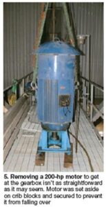
The first task after completing lock-out/tag-out procedures was to lift the 6-ft-tall, 200-hp fan driver off the gear reducer and relocate it outside the work zone (Fig 5). Horizontal lay down was not an option. The motor was placed vertically on 4 x 6-in. crib blocks over a structural cross support under the walkway grating and secured with rigging straps and a chain fall.
Rigging the gear reducer for its removal was easy, Rettke continued. But once the heavy component was lifted up, everyone quickly realized the combined length of the rigging and the gearbox was longer than the opening provided by the equipment doors between adjacent cells. The jams between the equipment doors and the personnel access doors located immediately below them were interference points. Re-rigging using the shortest straps possible did not solve the problem.
So off came the five jams on the affected street, but with unintended results. The structure had settled over time and some vertical members, when relieved of the bolted door jams, spread apart while others move inward. Portable power rams and come-alongs would be needed to replace the jams after the new gearbox was installed.
The next challenge involved the transfer of the 2700-lb gear reducer from the chain fall to the mobile crane, so it could be lowered to the ground. Changing hooks involved rigging under tension and had to be done very carefully by experienced personnel.


Job analysis. After the damaged gear reducer was replaced and the job completed, the Higgins CBM program kicked in. Personnel who had participated in the project believed a safer and faster procedure was needed for change-out of gearboxes. Others agreed and a dialog between the plant, represented by the then maintenance manager, Ron McCallum, and Dave Cairns, a maintenance mechanic, and the engineering department
The goal: Design a fixture that would allow closer rigging distances between the chain-fall hook and gear reducer, facilitate moving the gear reducer through each cell, and provide a safer way to transfer the gearbox from chain fall to the mobile crane.was initiated.
The fixture designed and fabricated is both robust and simple. A large plate with ribbing on the top side was constructed to meet applicable safety and engineering standards. It is attached to the gear reducer with four bolts. Three lifting eyes were provided: a single large eye in the middle for the chain-fall hook to pick the gear reducer off the fan (Fig 6), and smaller eyes on either side for the straps that would connect to the mobile crane. Eyes were positioned to ensure that the gear reducer would be lifted and transported on an even keel. If necessary, small spacers can be placed between the plate and gear reducer to assist in leveling.

Rigging height was reduced to just over 6 in. between the chain-fall hook and the gearbox, eliminating the need to remove door jams between adjacent cells along the monorail path. The rigging and gear reducer passed comfortably through the equipment doors (Fig 7). The fixture enabled safe and rapid transfer from the chain fall to the mobile crane. With the gear reducer suspended by the center lifting eye, shackles and rigging straps were attached to the eyes on either side of the chain-fall hook. The mobile-crane then took the load using the rigging straps and the chain fall was unhooked from the center lifting eye (Fig 8). Finally, the mobile crane lowered the gear reducer to the ground (Fig 9). Handling steps were reversed to lift and install the replacement gearbox. Fig 10 shows the job completed.

Measurable benefits. The next time a gear reducer was changed out, the job took fewer than 10 hours start to finish—less than half the time it took to do before the fixture was available. Steps taking the most time were the unbolting of the gearbox from its framework and the fan hub, not the physical lifting and transfer of gear reducers as before.
Rettke said that because gearboxes are subject to “Murphy’s Law” and likely to fail at the worst possible moment, reducing by one-half the timerequired for personnel to be in a very hot ACC cell with little air movement is a safety bonus.
Looking ahead, Rettke added, work has begun on the design of two more fixtures to facilitate ACC work. One is a bracket/support system to secure the fan blades and hub in position while removing the gearbox. It also will reduce the amount of time required to realign the gear-reducer hub to the fan hub. The second fixture will allow personnel to lift the motor and then rotate it to a horizontal position, either to remove the motor from the ACC cell or for temporary lay down on crib blocking. CCJ