


Manmade ponds reclaim storm water, build community relations
Challenge. In 2007, the Minnesota Municipal Power Agency pursued a unique approach to water conservation by constructing clay-lined ponds at its Faribault Energy Park. The network of ponds reduces the burden on the local aquifer, collects and reclaims storm-water runoff for plant use, and provides a place where the community can fish, picnic, and walk trails. Following the owner’s innovative conservation efforts, the plant O&M team implemented several simple methods for further reducing water consumption.
Solution. The facility was designed with hydrological features that keep storm water onsite and prevent discharge to the city treatment works and nearby surface waters—specifically:
- A network of small ponds to capture storm water and snow melt.
- Routing of road and plant drains to a storm-water collection pond.
- Topographical layout to maximize capture of rain and snow-melt runoff.
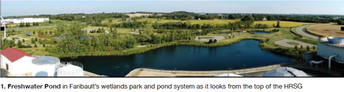
Makeup water for the cooling tower and steam plant is drawn from the large pond (named the Freshwater Pond) shown in Fig 1. Three other ponds, separated by overflow weirs, connect the storm-water retention pond to the Freshwater Pond (Fig 2). All ponds collect rain water and snow melt.
Plant and road drains are routed to the storm-water pond for use as plant makeup. The oily water separator shown in the diagram is equipped with a series of baffles to trap any oil that might be carried along with plant drains, forcing water to exit below the surface line where the lower-density oil would accumulate. If oil residue were ever to reach the storm-water pond, its below-grade discharge pumps would prevent oil migration further downstream.
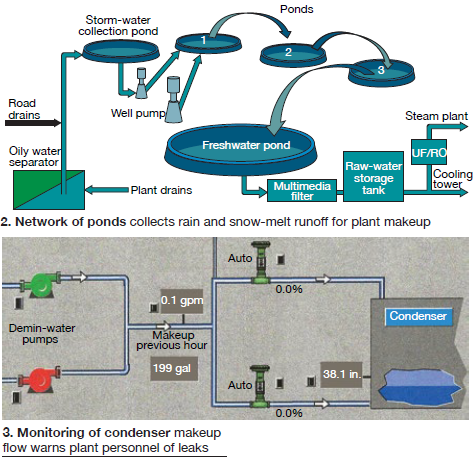
Level-control pumps discharge the contents of the storm-water collection pond into Pond 1, which then gravity-drains to each downstream pond via overflow weirs, eventually collecting in the Freshwater Pond for plant makeup. When the Freshwater Pond level drops to a predetermined set point, a well pump supplies water to Pond 1, which in turn discharges to each downstream pond until the level is restored in the Freshwater Pond.
The O&M team devised a simple but effective monitoring program to further conserve water. Operators routinely monitor the makeup flow to the condenser. If flow increases, it indicates that steam or water is leaking from the plant. Fig 3 shows a graphical display of condenser makeup flow including the totalized gallons for any given previous hour.
In a cycling plant, data can be misinterpreted if documented too soon after a startup, because the condenser level may rise above the control set point for several hours following a start. The data are meaningful only after the actual condenser level matches the control set point for a few hours at steady-state conditions.
During routine planned surveys, or when the team notices an increase in condenser makeup flow, they use several different techniques to pinpoint leaks. A simple, inexpensive temperature gun works well for locating elevated pipe temperatures downstream of valves. Ultrasonic probes are effective for detecting hot- or cold-water valve leakage.
An infrared camera is sometimes used as well, although pipe insulation makes it difficult to detect temperature differences across valves. Since downstream drain-valve piping may still be hot because a valve is open during startup, the team performs leak surveys after allowing time for piping to cool.
Results. The pond system provides several significant benefits:
- Eliminates storm-water runoff to local waterways.
- Reduces groundwater consumption. For example, the 6 million gal collected during one unusually high-rainfall month was sufficient to support plant operation for about 100 hours.
- Provides the community with a manmade wetlands park that supports recreation and wildlife conservation. One local conservationist even donated wood-duck and bluebird houses.
- Produces no point-source discharge. This means no NPDES (National Pollutant Discharge Elimination System) permit (cooling-tower blowdown is discharged to the city under a POTW (Publicly Owned Treatment Works) contract. Also, the facility qualifies for a “no exposure” storm-water permit.
A routine leak survey provides benefits as well. On one recent occasion, condenser makeup rate elevated to 40 gpm, and a subsequent leak survey identifiedseveral faulty valves. This allowed personnel to order required parts on time for the plant’s upcoming planned outage. The makeup rate returned to a normal value of 7 gpm following repairs.
Project participants
Shawn Flake, operations manager
Bob Flicek, maintenance technician
Improving drainage, monitoring of water in HRSG steam header
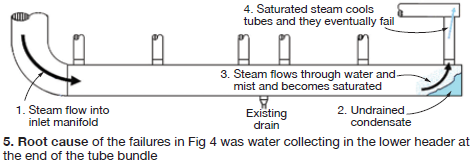
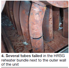 Challenge. Faribault’s heat-recovery steam generator (HRSG) had experienced several reheater tube failures, all at the end of a tube bundle next to the outer HRSG wall (Fig 4). The plant is designed to cycle frequently, which creates stress on boiler tubes during startup and shutdown. Plant personnel found tube failures on both the upper and lower portions of the secondary reheater downstream of the desuperheater-spray injection point.
The design of the lower header included only one 2-in.-diam drain line in the center. This did not allow adequate drainage, resulting in an accumulation of water in the far end of the header (Fig 5). It was clear this excess water was collecting in the lower header under the tube bundle.
However, we couldn’t tell if it was blocking the steam flow, causing the affected tubes to overheat, or whether the tubes were saturated, causing them to remain cooler (and shorter) as the other tubes in the bundle expanded.
In either case, staff knew it had to improve the drainage from the header as well as eliminate the cause of the tube failures. To add to the challenge, there were no access doors near the repair sites, which significantly prolonged the forced outage. It took 8 to 12 hours at each end of the work to cut access holes and then weld the wall material back in place.
Solution. Faribault personnel worked directly with a reputable HRSG engineering firm to minimize (or eliminate) these tube failures and reduce the amount of time spent in outages. To validate staff’s suspicion that the outer tubes were remaining cooler and thus being stretched by the hotter tubes in the bundle, temporary thermocouples were installed on multiple tubes on both the upper and lower headers along with a data logger. The data confirmed our suspicion, showing a significant temperature difference between the outer tubes and those located four to five tubes in.
Based on the data, the following modifications were made in timely fashion:
- Tapped a second 2-in. drain line into the lower header on the far end where water was collecting and tied it and associated expansion loops into the existing drain pipe.
- Automated the controls and incorporated a means of detecting water in the pipe. This included (1) replacing the manual drain valve with an automatic one for easier control, (2) installing a level transmitter and condensate pot for moisture detection so staff could monitor water level in the lower header, and (3) installing a thermocouple in the drain line so staff would know to close the valve after water was removed and before steam flows through the pipe for an excessive amount of time.
- Installed access doors to both the upper and lower header locations for inspection and repair.
- Installed an access platform to allow easy entry for inspection and repair.
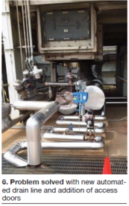 Results. The new lower-header drain effectively removes entrained water from the header, and the new instrumentation allows the control-room operator to verify that the drain is performing as designed (Fig 6). The instrumentation further benefits the plant by allowing operators to quantify increases in water drainage that could indicate a possible desuperheater valve leak or spray-nozzle failure.
Since automating the drain system, plant has experienced no additional cracked tubes—or costly forced outages. The two new HRSG access doors on the top and bottom of the header allow convenient, routine visual and NDE inspections of the suspect tube-to-header areas. Fig 6 shows the new lower access door on the side of the HRSG.
Project participants
Bob Burchfield, plant manager
Shawn Flake, operations manager
Ben Garrison, maintenance manager
Faribault Energy Park
Owned by Minnesota Municipal Power Agency
Operated by NAES Corp
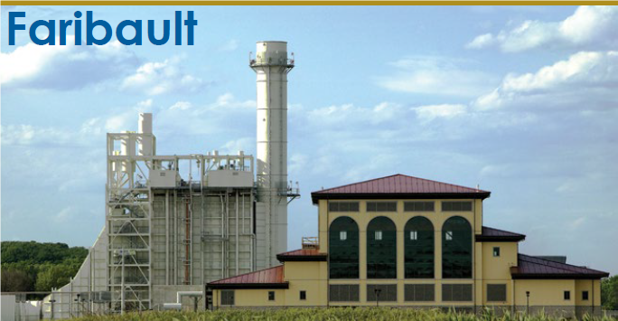
265-MW, dual-fuel, 1 × 1 combined cycle located in Faribault, Minn
Plant manager: Bob Burchfield