


Installing battery disconnects allows safe, reliable testing, maintenance
Best Practices Award
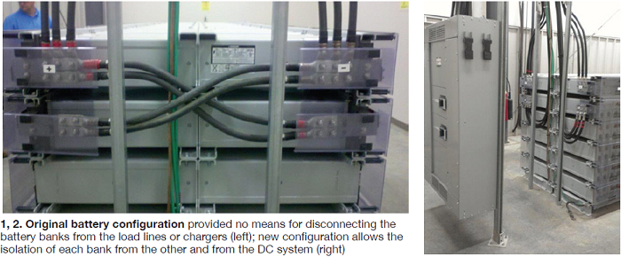
 Challenge. The battery banks for the BOP and the DCS backup system actually were two battery banks in parallel with one another (Figs 1, 2). The banks—two VRLA batteries consisting of 60 cells each at 125-V DC—connect to the chargers and the rest of the DC system. Loads on the system include the UPS panel, which provides 120-V AC power to the DCS system as an emergency backup, as well as a DC lube-oil pump and a DC seal-oil pump, both of which are part of the steam turbine system.
Since there was no breaker between the charger or load lines coming from the battery, there was no way to isolate one battery from the other without the potential for high amp loads caused by line load or the inherent voltage present on DC systems. Plant staff sought a safe and reliable means to isolate the parallel battery banks for maintenance and testing.
Solution. While performing biannual load testing on the batteries, representatives of the testing company asked if we had considered installing a breaker panel on the leads between the battery terminals and the charger. Each time load testing was completed, there was a great deal of concern to ensure that the chargers were isolated; plus, isolation of the UPS/inverter panels and each of the oil pumps to ensure that there was no live load on the DC system which could cause a large current surge while unbolting and disconnecting the battery cable leads.
The constant 120-V DC power supply cannot be avoided, even with the installation of breakers, but the presence of breakers would ensure that any and all chance of load and subsequent high current is eliminated. Also, with the installation of a breaker on each of the battery banks, one battery could be easily isolated from the other, leaving the second battery available for limited use if needed. Then when testing is completed on the first battery, the configuration can be swapped to the first battery and the second battery could be isolated and tested independently of the first.
Several DC system specialists were consulted to determine the validity of the project. One downside to the project is that the DC system would lose its inherent “hardened” state of providing reliable DC power to the needed load regardless of current draw—that is, a loss of current unless the device breaker was to trip.
The new disconnects were sized to ensure that that the device breaker would trip before the battery disconnects would come offline. Utilizing this feature, plant management came to the conclusion that installation of the disconnects would provide a much-needed safety feature to the system for contractors and plant personnel performing maintenance and testing on the VRLA batteries.
Results. The battery disconnects were installed during the spring 2013 outage and prior to the battery load testing that was performed. After the disconnects were installed, they were utilized to isolate each of the batteries and transfer from one battery to the other during the testing process. Procedures were supplied to the plant for proper isolation and energization after isolation. All evolutions were completed satisfactorily and the contractor performing the testing was very pleased with the safety of the new configuration as was plant staff involved with the isolation, testing, switching from one battery to the other and energization of the system.
Project participants:
Glenn A Brons, maintenance coordinator
John Sorrick, lead IC&E tech
Dave Zalfen, IC&E tech
Cooling-tower blowdown reclamation reduces water use, processing costs
Best Practices Award
Challenge. During normal operation, cooling-tower blowdown enters the wastewater system when it is discharged into one of two storage tanks: tank 1 holds 1-million gallons; tank 2, 2.5 million (Fig 3). The wastewater then is pumped to the brine concentrator (BC) where it is evaporated, creating a slurry within the BC. This slurry is processed further and the evaporated water condensed for reuse in the plant.
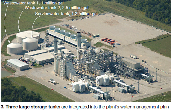
Normally, this distillate is pumped back into the cooling-tower basin as part of the makeup. If the basin is full and cannot receive additional makeup water, such as when the plant is shut down overnight, distillate is routed to the service water tank (1.2 million gallons), which normally is maintained at about 40% full. The challenge was to develop storage and reuse options for reclaiming the cooling-tower blowdown.
Solution. Prior to the start of each run season, wastewater tank 1 is designated the “clean” wastewater tank and cleaned to ensure it contains no solids. All BOP wastewater transfer pumps are aligned to wastewater tank 2. During the run season, tank 2 becomes the primary wastewater tank, and tank 1 is used only if tank 2 becomes full.
At the end of the run season, wastewater is processed normally, with wastewater tank 1, if used, processed first. Once the cooling-tower basin and the service water tank are at capacity, the cooling tower, which now contains clean distillate, can be blown down to the clean wastewater tank (tank 1) as needed to allow the BC to remain in service.
When the power block is restarted and cooling-tower makeup is needed, plant personnel rent and set up a 6-in. diesel driven pump along with 100 ft of discharge hose that takes suction from the drain of wastewater tank 1 and pumps it over the wall of the cooling tower, thereby reclaiming distillate that was blown down from the tower basin.
Results. Once the use of wastewater tank 1 as a clean tank proved effective, plant staff made piping changes to allow the wastewater pump (which normally pumps wastewater to the BC) to pump the clean water from wastewater tank 1 into the cooling tower. The team installed the necessary piping and valves to connect the wastewater pump outlet piping to the distillate piping as it leaves the wastewater system and heads to the cooling-tower basin.
Project participants:
Dwight Beatty, O&M manager
Chuck Berg, plant engineer
Glenn A. Brons, maintenance coordinator
Rob Mallett, compliance manager
Entire O&M staff
Outage safety observers
Challenge. Over the years, plant personnel have come to recognize several challenges in conducting outages safely, including these:
- 1. Post-outage reviews with contractors and plant staff have shown a recurring theme of contractor attention to safety requirements diminishing as the outage progressed. Plant staff implemented a change that requires an on-duty operations staff member to perform safety observations of contractors every two hours, rotating throughout the day so that all contractors are observed at least once. Although this improved the safety culture, plant personnel believed there was still significant room for improvement.
- 2. Contractors need to be reminded multiple times over the same type of safety issue during the course of the outage.
- 3. The plant only has radios for plant communications at its disposal. During outages, extra radios are rented to cover each contractor; however, for large outages it is not feasible to have a radio for every contractor employee. A radio is checked out to each contractor crew lead; however, issues can still arise in the event of a plant emergency and the crew lead with the radio is not located with his crew.
Solution. These challenges were reviewed by the safety committee and plant staff, and the following solutions were implemented with the full agreement and financial support of the plant ownership:
- 1. Safety observers are designated during all outages for both day and night shifts as a separate job function. Their responsibility is to patrol the entire plant reviewing all outage operations for any safety issues that have or may arise. The safety observer also attends the daily outage meeting (which includes all contractor and plant leads) to review work that is going on that day, as well as any concerns or observations anyone might have.
- 2. The plant has adopted a zero tolerance policy toward violations in the core safety procedures that could lead immediately to a loss of life—such as LOTO, confined space, and fall protection. This policy requires that following a first violation, the contractor employee is removed from site for one day with return dependent on permission from the contractor’s supervisor; following a second violation, a contractor employee is removed from site permanently. These policies are discussed with all contractors during the pre-outage meeting and safety orientation.
- 3. The plant has installed an air horn for personnel notifications during an emergency. All crew leads still carry a site radio, but if any site personnel find themselves without a radio when the warning horn is activated, then they have instructions to make their way to a person with a radio or the control room for further instructions.
Results. Since these items were implemented at the beginning of 2013, the plant has performed two major outages with no contractor injuries and no violations to the core safety procedures. The incidences of having to remind contractors of smaller issues, such as housekeeping and permit closeouts at the end of the day, have been reduced considerably. In addition, contractor feedback has been prodigiously positive.
Project participants:
Entire operations and maintenance staff
Innovative forced-outage strategy
 Challenge. An unplanned failure of steam-turbine-exciter pass-through shunts during a peak operational period for the plant motivated some “outside the box” planning and strategy to restore the plant to operational status as safely, quickly, and cost-effectively as possible. Normal methods for resolving the issue would have kept the plant offline or de-rated for an extended period at great expense to the plant ownership group.
Solution. Plant staff, with the approval of the OEM, worked with a third- party provider to reverse-engineer and manufacture new pass-through shunts domestically in much less time than the OEM could normally manufacture and deliver them from its overseas manufacturing facility (six weeks versus six months).
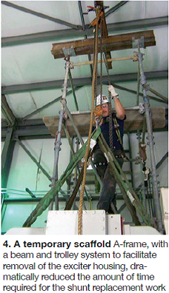
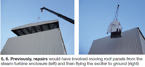
Additionally, plant staff worked with an engineer from a local scaffold supplier to design a temporary scaffold A-frame with a beam and trolley system to facilitate removal of the exciter housing so that the shunt replacement work could be executed (Fig 4). The scaffold design allowed the work to be safely executed in half the time and at a much lower cost than using standard repair procedures, which had included using a crane for removing the roof panels from the steam-turbine enclosure (Fig 5), removing the exciter housing (Fig 6), and then the subsequent reinstallation of the exciter housing and roof panels.
Results. Outage time to make the repair was reduced from eight days to four using this innovative repair method. The OEM originally quoted more than $220k for the repair. The new method cost less than one-third that amount. Using creativity and thinking “outside the box” allowed the work to be completed safely, cost-effectively, and efficiently. The plant was able to avoid an extended de-rate and downtime by creatively designing an alternative repair method.
Project participants:
Entire operations and maintenance staff
Dogwood Energy Facility
Owned by Dogwood Power Management LLC
Operated by NAES Corp
650-MW, gas-fired, 2 x 1 combined cycle located in Pleasant Hill, Mo
Plant manager: Pete Lepage (former)