


Day One workshops a meeting on their own
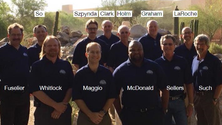
The 7F Users Group steering committee voted two relative newcomers to lead the organization through its 2015 annual meeting. Robert LaRoche of SRP and TECO Energy’s Ed Maggio were elected chairman and vice chairman, respectively, for the 2014-2015 term (photo). They replace SCE’s Richard Clark and Direct Energy’s Ed Fuselier in the top positions. Both LaRoche and Maggio joined the committee after the 2013 conference.
Filling the shoes of Clark and Fuselier will be no easy matter given the size of the organization and the work involved in lining up both user and vendor speakers for the five-day meeting, which also includes special workshops, a golf tournament, and a two-evening exhibition. The 2014 event, conducted May 19-23 at the Sheraton Wild Horse Pass Resort & Spa in Phoenix, hosted more than 250 users for the week and 68 exhibitors each evening.
7F steering committee, 2014 – 2015
Chairman: Robert LaRoche, SRP
Vice Chairman: Ed Maggio, TECOEnergy
Treasurer: Peter So, Calpine Corp
Richard Clark, SCE • Ed Fuselier, CPV • Jeff Gillis, ExxonMobil Chemical • Sam Graham, Tenaska Inc
Art Hamilton, Emera Inc • Robert Holm, Occidental Chemical • Justin McDonald, Southern Company
Ben Meissner, Duke Energy Corp • Jim Sellers, Entegra Power Group • David Such, Xcel Energy
Eugene Szpynda, NYPA • Paul Whitlock, Dominion Resources Inc
The conference ran with military precision thanks primarily to a “no-excuses” committee and an efficient and helpful event-management team headed by Sheila Vashi. Requirements critical to success—good food and lots of it, trouble-free audiovisual equipment, a technical program dominated by user presentations, quality raffle gifts, and a team of knowledgeable floor leaders to facilitate a meaningful exchange among attendees—met or exceeded expectations.
Save the date: The 7F User Group’s 2015 conference will be held in Denver, Colorado, May 11-15 at the Sheraton Denver Downtown.
The workshops
Not too many years ago, the 7F Users Group annual meeting was characterized by a “soft start” on Monday—plenty of time to visit with colleagues and enjoy an adult beverage or two. No longer. Day One has become academically demanding—a cerebral marathon in a sense—if you arrive early enough to attend the first of the two four-hour workshops scheduled.
The first workshop at the 2014 conference was HRST Inc’s respected HRSG Spotlight Session. A quick lunch later, PSM’s top engineers brought attendees up to speed on proven hardware solutions for the 7F compressor, combustion section, and turbine.
Breakfast with HRST
Once again, the annual HRSG Spotlight Session proved its value as one of the industry’s top training workshops on F-class heat-recovery steam generators. This year, Lester Stanley, PE, and Rob Tretter teamed up to make the following presentations:
- Repair of damage to pressure parts.
- New unit checklist of lessons learned.
- Smart starts.
This article focuses on the first two presentations; more to come in the next issue of CCJ. Tretter began with tube leaks, stressing the importance of dealing with them quickly to limit damage to the affected tube and possibly to adjacent boiler components. First step is to pin-point leak location and confirm positively the material grade, pressure part size and wall thickness, joint design, and design pressure and temperature. Try to locate final drawings and the Manufacturer’s Partial Data Report (ASME Form P-4); confirm they match. Verify with field measurements when possible.
Next, review the affected unit’s history and collect data from previous repairs; check warehouse inventory for the availability of replacement tube sections. Determine the root cause of the problem to develop the best repair plan. Tretter stressed, “Fix the leak and fix the cause.” For leaks at the connection of the tube to either header, it is critical to incorporate the joint configuration into repair documentation.
There are many tube repair strategies to evaluate regarding effectiveness, time to correct the issue, and cost—including these: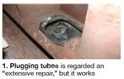
- Plugging in place.
- Cut your way in, weld your way out.
- Spread the headers.
- Raise or lower tube panels.
- Remove sidewall/casing.
- Replace tube panel.
Plugging in place sounds tempting, but don’t make your decision simply based on past maintenance experience with conventional industrial watertube boilers. The task is much more challenging in a HRSG and may make economic sense only when the leak is in a particularly difficult location. The procedure requires cutting out a “football” in both headers, plugging the tube, and reinstalling the football. Avoid making sharp corners (Fig 1) and follow the rules of the National Board Inspection Code.
Repairs that require a welder to cut his (her) way into the leaking tube obviously demands that perfectly good tubes be cut and removed temporarily. This is “R” stamp work and requires qualified welders following a qualified procedure, as well as NDE and preheat/post-weld heat-treat requirements. Tube plugging and cutting your way in/out rarely are the most economical solutions, Tretter said.
Spreading of lower headers may be an option for access to the affected area, depending on the location of the leak, interconnecting piping, and other factors (Fig 2). An engineering study is recommended to guide the spreading process and warn of possible collateral damage if specifications are exceeded.
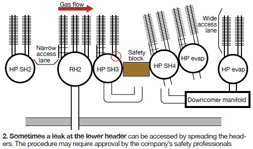
Alternatively, it may be possible to raise or lower panels to get to a leak (Fig 3) or gain access by removing a portion of the sidewall casing. Generally speaking, a leak at the upper header can be accessed by raising the affected panel. Lower the leaking panel if repairs are required on the lower header. This technique also can be used to replace an entire header and tube stubs. Tube-tie design details are required before making a raising/lowering decision to guard against panel “hang-up.”
Nozzle cracks are most common in downcomers—specifically at the downcomer-to-shell weld. Unit cycling is the main cause of this damage, with weld profile and weld quality other important factors. Keep in mind that nozzles typically are located at the ends of the drums so flexing on heat-up and cool-down impacts downcomers.
Nondestructive examination of the area where cracking is suspected should be your first step. Liquid-penetrant and magnetic-particle techniques were recommended by Tretter. Most often, the defect can be ground out and weld-repaired. Confirmation of a proper repair is by repeat NDE.
Defects extending into drum metal beyond the depth allowed by the ASME Boiler and Pressure Vessel Code—typically in the range of ? to 3/16 in.—must be repaired according to the National Board Inspection Code (NBIC). Tretter reviewed the recommended procedure for below-surface repairs of nozzle cracks:
- Determine root cause of the cracking, if possible.
- Excavate and completely remove existing defects; confirm with NDE.
- Prepare weld area to bright metal and preheat to NBIC RD-1030.
- Make weld repair.
- Remove weld splatter and slag.
- Inspect and perform additional NDE if required.
Dewpoint 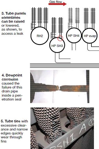 corrosion occurs when metal surfaces cool below the exhaust-gas dewpoint—typically 112F-120F when burning natural gas. Concerns include corrosion of tubes and fins at the cold end of the unit, of floor and roof pipe penetrations, and of the stack wall and expansion joint area, plus liner and casing deterioration.
Fig 4 shows a drain pipe inside a penetration seal that suffered dewpoint corrosion and failed. There should be a drain hole in pipe penetrations; keep it free of debris. A slight amount of gas flow through the hole will keep the bellows area dry and help prevent drain-line corrosion.
Stack dampers help prevent dewpoint corrosion, Tretter told attendees. But do not close the dampers immediately after shutdown, he cautioned, because the hot gas at the front of the unit will promote steam production in the IP and LP drums and possibly cause safety valves to lift. Monitor exhaust temperature, the boiler expert suggested, and keep it above the dewpoint for the fuel being burned. Run a dehumidifier in the exhaust-gas space after the damper is closed.
Pipe and tube repair and replacement is a relatively common maintenance activity at combined-cycle plants—unfortunately. Material damage/wastage is attributed most often to dewpoint corrosion, flow-accelerated corrosion (FAC), and improperly designed, operated, and maintained attemperators. Repair or cut out and replace damaged components according to NBIC rules. This means adhering to preheat and post-weld heat treat requirements and using proper NDE procedures. Don’t forget to have a certified inspector to verify welder qualifications, filler metal, and documentation.
Panels. Widespread problems, such as those that might be linked to improper water treatment, can dictate replacement of panels or of entire sections of the boiler—the HP evaporator, for example. The appropriate course of action will be heavily influenced by the extent of damage and specific design details of the boiler and its heat-transfer surface. Tretter discussed some of the alternative repair/replacement scenarios, scheduling, engineering work required, lead times for sourcing material, etc.
He recommended that owner/operators consider design upgrades when major work is required. Examples mentioned: Upgrading materials in the back end of the HRSG to chrome steel to protect against FAC, and reconfiguring panel geometry to accommodate cycling of the unit and improve gas-side cleanability, etc. Tretter stressed the importance of detailed planning to assure a smooth project.
HRSG lessons learned
Stanley and his colleagues at HRST spend a significant amount of their professional lives in and around HRSGs and they know better than most people in the industry about the issues associated with this type of boiler. Stanley compiled some of that information to create talking points for his presentation, “New HRSG Checklist.” His goal: Help owner/operators prepare more meaningful new-equipment specifications and reduce the lifecycle costs of their boilers.
Tube ties in Fig 5 have excessive clearance and narrow edges contacting tube fins, an arrangement conducive to “rattling” during unit operation. Rattling wears the fins, increasing the clearances, and exacerbating the problem, as this photo of a 2-yr-old boiler clearly illustrates. HRST recommends carefully reviewing the tube-tie design, especially in the first tube bundle, before signing off on the drawings. Stanley suggested placing tube ties every 10 to 12 ft, not 15 ft or more as often found.
Duct-liner hardware. Liner design must be robust to accommodate the turbulence and temperatures experienced in the inlet duct. The first 15 to 20 ft of the duct demands special attention, Stanley said. The casing should be stiffened there, stud pattern should be more dense, and studs more robust. Also, be sure to weld top and bottom washers to the studs.
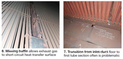
Gas baffles between adjacent tube panels and between panels and casing walls tend to fail over time because of the severe environment. Absent baffles, exhaust gas follows the path of least resistance and bypasses heat-transfer surface. Baffle design should be robust; ample support should be provided. No U-bolts! They allow rattle and cause tube wear. The baffle failure in Fig 6 was caused by stitch-weld cracks and unit cycling. Tube ties that restrict tube vibration are critical to success. It’s a system, Stanley said: Baffles rely on tubes for support, tubes rely on tube ties for support.
Flow distribution plates often are needed at the HRSG inlet to assure that the air-flow profile to the duct burner is consistent with top performance. But the difficult environment—including vibration and sudden temperature changes—often causes damage to this perforated plate. For new units, a careful design review is important. Look for successful experience at other sites to help guide decision-making.
Baffles between the inlet duct and HP superheater or reheater. The transition from the inlet-duct floor to the first tube section is prone to problems. Downward expansion of the tube panel can be more than 6 in. and tear loose baffles (Fig 7); or the panel can bow, with the same effect. Stanley urged users to closely check both the installation of baffles and assure proper clearances, as well as verify that tube-panel guides are installed correctly, to restrict bowing.
Drain pipe design/routing. Design of superheater and reheater drain piping doesn’t sound challenging but it must be given Stanley’s mention of drains that really don’t. He told the group that drains must have adequate capacity for condensate clearing, and must allow for tube bundle flexing during startups and shutdowns.
Impact of firing temperature on non-pressure parts. The firing-duct liner, and downstream tube ties, gas baffles, and viewports, often are damaged by overheating. One reason is that some design decisions—such as materials selection—are made based on the predicted full-load bulk gas temperature, and the peak temperatures in firing ducts (so-called hot spots) are higher.
Owners should carefully evaluate materials for liner sheets, studs and washers, tube ties, gas baffles, etc, before the design is finalized. Example: Consider upgrading from Type-304 to Type-310 stainless steel because of the latter’s better high-temperature properties.
Fouling of AIG lance nozzles. Lances for ammonia injection grids often are made from carbon-steel piping. Over time, they corrode and rust flakes plug some nozzles. The cumulative pluggage over years of operation, coupled with the decay in SCR catalyst activity, has the potential for creating a challenging operating paradigm before its time. The solution is simple: Specify Type-304 stainless steel for lances.
Tube cleaning. Anyone who has worked at a cogeneration or combined-cycle plant knows tube fins corrode and foul over time. Tubes must be arranged with appropriate lanes to permit penetration into the tube bundle by cleaning nozzles. A rule of thumb is to limit tube-module size to about 10 tubes deep. Access lanes should allow easy scaffold or skyclimber use.
Drum nozzles. HP-drum nozzle weld configuration is particularly important in HRSGs that cycle. For example, pass-through partial-penetration welds are susceptible to stress cracking. Specify a weld design that is compatible with the duty of your unit and be sure to establish proper drum ramp-rate limits.
Steam-drum doors are difficult to close correctly. Stanley stressed optimizing drum-door hardware to reduce steam-leak safety risks and specifying elliptical manways larger than the traditional 12 × 16 in.
7F performance, reliability enhancements
PSM, celebrating its 15th anniversary, conducted a comprehensive technical workshop that captured the interest of about 200 owner/operators for an entire afternoon. The company’sability to develop and bring to market so quickly its respected advanced gas-turbine components impressed many attendees.
President Alex Hoffs opened the four-hour special session for 7F users by emphasizing the company’s mission: “To help our customers operate their powerplants profitably.” Next, he reviewed the company’s commitment to safety, health, and the environment before introducing the featured speakers: Chris Johnston, director of airfoils engineering R&D; Dr Peter Stuttaford, director of combustion engineering R&D; Jesse Sewell, director of service engineering; and Chad Garner, manager of R&D machine integration.
Hoffs then summarized PSM’s products and services before yielding the podium:
- Complete range of capital parts, repair, field services, and monitoring for B-, E-, and F-class engines.
- Low-emissions upgrade solutions for mature frames.
- Sole source for aftermarket F-class GT performance upgrades.
- Independent technical and manufacturing capabilities to address product issues.
- Support of the total plant scope.
- Flexible commercial alternatives for transactional and long-term agreements.
Compressor reliability improvements. PSM may be best known to 7F users for its work on compressor reliability enhancements, some solutions dating back more than a decade. Johnston, who presented this part of the technical program, began by explaining how the company brings solutions to market quickly, using its redesign effort for the R0 blade as an example.
The engineering process is driven by customer need. In this case, multiple issues with OEM R0 blades were compromising GT availability for many owner/operators. First step, logically, is to identify the root cause of the problem. PSM engineers tested four sets of OEM blades in three different engines to gather data required for identifying contributing factors. Two primary responses were identified: a steady-state resonate mode and a transient mode.
This information prompted an airfoil redesign that reduced stresses in key locations and increased the operating margin. The first production blades were delivered to customers in 2008, only nine months after project start. Field validation, the final step in the process, has gone according to plan, Johnston said.
Fleet leaders among the more than 50 sets of R0 blades installed in 7221, 7231, and flared and unflared 7241 compressors have proven themselves through multiple inspection cycles—including in-situ, destructive, and NDE and dimensional inspections. The PSM R0 blade allows users unrestricted engine operation—fogging and online water washing included.
Johnston added that his company’s R0 and S0/S1 stator solutions address disc-cracking drivers identified in the OEM’s Technical Information Letter 1907. PSM recommends disc inspection prior to R0 install to confirm that the discs are defect-free.
The engineering manager went on from there with a review of his company’s other validated compressor solutions. High-cycle fatigue (HCF) and corrosion concerns associated with S0-S4, which contributed to airfoil failures, erosion of stator leading edges, and deterioration of vane-carrier rings, were mitigated by use of new materials and airfoil shapes. Other enhancements included an increase in the number of carrier ring segments, elimination of shims, and use of squealer tips.
The 7F fleet’s history of hookfit wear, fretting, stator twisting, and case wear associated with stator stages 13-16 were traced to straight hooks, insufficient part-to-part contact, and other design characteristics that PSM engineers changed to better accommodate the operating environment. Solutions are available for baseline and “Bigfoot”-modified cases. Validated enhancements include the following:
- Radial stator hooks to match radial case hooks.
- Radial mating surfaces between stator segments.
- Stator vanes ganged, or packed, into segments containing several airfoils to provide appropriate damping. PSM refers to this as its patented “hook ring” design.
- Wear coating for greater durability.
Johnston explained, by way of simple diagrams, the multiple stator 17 and exit guide vane (EGV) configurations for the 7F.03 available to accommodate all styles of inner barrels. This redesign effort was launched in 2005, initially to address hook-retention issues. Today, fleet leaders are beyond two-interval operation, he said. Design features include packed airfoil assemblies for damping as used in the solution for Stages 13-16. Welded assemblies with radial features are other design upgrades.
Combustion section reliability
solutions for the 7FA were covered by Stuttaford, who began with with a review of the company’s standard “drop-in” 7FA premixed combustor, which operates at 9 ppm NOx or below on natural gas over the operating load range of interest to most owners.
During the last five years, he said, PSM has equipped several engines with full sets of these combustors, adding that individual components—including fuel nozzles, liner, liner cap, transition duct, flow sleeve, etc—are piecewise compatible with OEM hardware. This was important to attendees looking to upgrade but not replace their combustion sections.
The two topics Stuttaford focused on were PSM’s durability upgrade for endcovers and its new FlameSheet combustor. First field installation of a FlameSheet combustor is scheduled for 2015.
Attendees would hear a lot about the cracking of endcover insert braze joints during the conference and what to do about it. Analysis of field experience indicates such cracking is most likely to occur in gas turbines burning unheated fuel. The high thermal gradients between cold fuel passages and the hot cover can initiate cracking of the braze joints, thereby creating the opportunity for fuel to leak into and contaminate burner-tip cooling air for OEM-design fuel nozzles. This, in turn, reduces the tuning window and can make emissions compliance more challenging.
To eliminate this fleet issue, PSM now offers a robust welded endcover; five sets have been sold. Note that, for the company’s fuel nozzles, tip cooling-air passages are arranged in a manner to prevent contamination by fuel, thus there is no possibility of emissions-compliance issues caused by cracked endcover joints.
Stuttaford’s announcement of PSM’s FlameSheet combustor probably was “news” to many in the room. Extended turndown capability, durability, and fuel flexibility are key attributes, Plus—and a really big plus for owners with mixed F-class fleets—the same combustor can be used in both 7FAs and 501Fs. The FlameSheet combustors for both engines are identical apart from liner and flow-sleeve exit ends, because they mate with different transition pieces. Key takeaways from the presentation:
- NOx and CO emissions at 50% to 100% of the engine full load rating are 9 ppm, as verified in a high-pressure rig operating at full engine conditions.
- Turndown (<10 ppm CO) to about 30% of full load while maintaining continuous emissions compliance.
- Fuel-gas flexibility. Ability to accommodate variations in the Modified Wobbe Index of up to 30% (no liquids). Regarding gas constituents by percentage in the fuel, FlameSheet requires only 40% methane.
- Combustion inspection (CI) interval life of at least 24,000 hours/900 starts; however, expectation is that FlameSheet will have a 32K option, based on field experience.
- Model-based control is not required for the FlameSheet combustor; existing OEM or retrofit controls can be modified.
- Liquid fuel. FlameSheet can be equipped for dual-fuel service, with NOx at 42 ppm (wet).
Combustion tuning. Stuttaford transitioned to combustion tuning, noting that a Combustion Dynamics Monitoring System (CDMS) is needed to monitor dynamics levels that if exceeded could cause hardware distress—possibly even severe damage—or perhaps lean blowout.
Automated tuning was state-of-the-art in 2011 but the technology has advanced quickly since, the speaker said. One of the factors driving enhancements in PSM’s AutoTune, he continued, is the variability in fuel composition attributed to shale gas production. This has a significant impact on dynamics.
Here’s how Stuttaford explained AutoTune’s advantages: Compact, built using industrial-grade electronics (no PC). Its self-learning tuning logic is external to the existing GT control system; therefore, control-system processor resources are not consumed. He stressed that the system is highly customizable to meet the specific needs of each site and explained by way of an example how AutoTune self-learns and retains the acquired knowledge in a historian.
The value of this capability over time: Less tuning is required to maintain compliance and protect the engine. A chart used in the presentation showed that, in the first four months after installation on one machine, 90 tunings were necessary. That number was reduced to a dozen for the following four-month period.
Another capability of AutoTune, Stuttaford told the users, is a power-boost option called Power+. When ambient conditions allow, the firing temperature can be pushed via AutoTune to the OEM’s recommended operational limit to extract up to an additional 3.5 MW from the unit while maintaining NOx in compliance.
Performance upgrades. Johnston returned to the podium to explain the company’s latest work on performance improvements. He said that the goal of PSM’s Gas Turbine Optimization Program is to keep existing assets relevant and profitable throughout their lifecycle. GTOP leverages PSM’s proven platform technology (combustion system has been operating since 2005, airfoil designs since 2006) to improve engine performance and efficiency while increasing reliability and flexibility as well; NOx emissions are maintained at less than 9 ppm.
The first commercial GTOP3.0 packages have been operational since 2011, and the first GTOP3.1 is now in service. Both packages provide output and heat-rate improvements. In field tests, GTOP3.0 demonstrated a 4.3% bump in output for a 2 × 1 combined-cycle application (an 8.5-MW increase for each gas turbine and 4.9 MW for the steamer) accompanied by heat-rate reductions of 1.3% in simple-cycle and 1.0% in combined- cycle arrangements. GTOP3.1, which adds a compressor upgrade to the GTOP3.0 package, is predicted to provide a simple-cycle power boost of up to 8.5%, a simple-cycle heat-rate reduction of up to 2.4%, and a combined-cycle heat-rate reduction of up to 1.5%.
Both packages can be arranged for standard- or extended-lifetime operation modes, and include the flexibility to switch between modes as the operator chooses. The standard maintenance interval is 24K hours/900 starts, extended is 32K/900.
Johnston put up a 7FA cross section on the screen and walked the group through the components associated with the GTOP3.1 package. Here’s what he identified, moving from the air inlet aft:
- The 3.1 package incorporates a redesign of the compressor front end (R0/S0/S1 for flared, R0/S0/R1/S1 for unflared), that delivers increased inlet air flow.
- The GTOP3.0 combustor features:
+ Low-pressure-drop flow sleeves.
+ Effusion-film-cooled transition pieces.
- PSM’s automated tuning system, AutoTune, to optimize combustor life.
- The GTOP3.0 turbine features first- and second-stage turbine technology upgrades:
+ First-stage nozzles of nickel-based alloy; reduced cooling-air requirements. Regarding the latter, Johnston noted that the less air required for cooling, the more is available for power generation.
+ First-stage buckets of PSM117 material with cast-in tip cap.
+ Second-stage nozzles having full-surface TBC; reduced cooling-air requirements.
+ Second-stage buckets having full-surface thermal barrier coating (TBC); reduced cooling-air requirements.
The upgraded combustor and turbine components included in the GTOP packages maintain interchangeability with standard 7F components. Additionally, repair technologies to recondition upgrade designs are consistent with standard 7F hardware.
Rotor solutions. Garner’s presentation essentially was a review of PSM’s capabilities in rotor analysis, design and repair solutions, and life extension. Most attendees were familiar with the company’s replacement parts for the 7F compressor and hot section, but likely knew little about its growing rotor business. By the time of the meeting, PSM had conducted rotor overhauls on three 7FAs and one 6B, and was expecting to receive its first 7EA rotor in June 2014. Also announced at the meeting was PSM’s full service readiness for the 501F.
Perhaps the most interesting part of the presentation was examples of repair solutions—including as-found photos, engineering analysis, redesign, and re-work—for cracking found in compressor rows 13 and 17, patch-ring restoration, compressor clocking, etc. Recommendations for R1 turbine-disc findings seemed to be of particular interest to the group. Garner said if there were no findings, all PSM suggests is a simple blend/polish/peen and some re-contouring to reduce stresses. For small cracks, the solution typically is localized blending and re-contouring. Cracks “beyond repair” require a replacement R1 disc and re-design of the cooling slot.
Controls and monitoring. Sewell spoke to PSM’s developing expertise in controls services and the capabilities of its monitoring center. The company now has in-house expertise for the major gas-turbine control systems—GE, Siemens, MHI, Emerson—he told the group. It regularly participates in controls upgrades/replacements to accommodate DLN conversions, one of PSM’s core competencies. Plus, it provides controls TA services as part of re-commissioning and combustion tuning activities. Sewell is one of the industry’s gurus on combustion tuning, having been involved in the design of early systems to support PSM’s LEC-III DLN conversions that drove NOx to sub-5 ppm—numbers virtually unheard of nearly a decade ago when the system was introduced.
The I&C expert went on to list some highlights of the company’s controls-related activities over the last couple of years—including international commissioning, LEC-III conversion with controls replacement, cold-weather tuning, dual fuel to gas-only conversions, 7FA AutoTune wide-Wobbe upgrade for an Ovation™ system to accommodate fast/low-NOx starts, and AutoTune installations and CDMS integration for Mark Ve, VI, VIe and Ovation platforms.
PSM now monitors 13 LTSA sites (24 gas turbines, three steamers) as well as nearly an additional 100 engines with PSM hardware allowing for remote analysis. The company’s real-time monitoring activities include periodic reporting of engine performance and predictive analysis to guide O&M activities. PSM capabilities are in line with what the leading utilities are doing regarding M&D centers. CCJ