


Teamwork brings major HRSG repair project in on schedule, at budget
During the “bubble years” 2000 through 2004, about 250 combined cycles were commissioned in the US. The only way to have manufactured and installed this much equipment in five years, given the country’s resource pool (people and materiel), was to standardize designs. One of the general assumptions made was that efficient F-class combined cycles would operate base-load. Minimizing the number of start/stop cycles (on paper at least), and assuming conservative ramp rates, simplifies the engineering effort.
But the market did not need so much base-load combined-cycle capacity, until perhaps now, and most of these plants were required to cycle—some daily and off on weekends—to pay the mortgage. Thermal cycles, pressure cycles, water and steam chemistry in and out of recommended limits, etc, took their toll and equipment aged much faster than expected. At least a few experts estimate that half the design lifetimes of some critical equipment have been consumed in 10 years or less.
Heat-recovery steam generators (HRSGs), indestructible as they might look, may have suffered most. These hunks of iron between two money machines often get no respect. You find lots of “turbine people” in combined-cycle facilities, but relatively few “boiler people.”
Visual inspections identify fouled finned tubes, liner damage, cracking at drum nozzle penetrations, etc, but “what lies beneath”—such as flow-accelerated corrosion (FAC), corrosion fatigue, thermal fatigue, under-deposit corrosion, incompatible metallurgy—only can be detected by a rigorous program of tube sampling and/or nondestructive examination considered unnecessary by some decision-makers.
The “real bad things” typically are identified only after an operator on rounds spots steam seeping from under insulation, makeup requirements skyrocket, or tubes are found separated from headers. But by then there are no easy fixes and corrective action is expensive.
 Ontelaunee Energy Center (OEC) is a case in point. The nominal 550-MW, 2 × 1 combined cycle, powered by W501FD2 gas turbines, was designed by WorleyParsons Group Inc for base-load service. It began commercial operation late in 2002— the middle of the bubble. The Reading (Pa) plant was commissioned by Calpine Corp and cycled daily, or less frequently, until relatively recently. OEC was bought by LS Power Equity Partners in October 2005 when Calpine was forced into bankruptcy and resold a year later to Dynegy Inc. Today it is managed by Dynegy Power LLC.
Wear and tear on the plant’s two HRSGs, including failures of pressure parts, hinted as far back as fall 2007 that design changes would likely be needed for the boilers to operate as required by the market. Field modifications last fall to implement the necessary design enhancements involved a 56-person onsite contractor staff and about 20,000 hours of craft labor within a six-week outage window. And this was only part of the work being conducted during the longest and most complex outage in OEC’s history.
For challenging boiler work of this magnitude to meet both schedule and budget targets dead-center is a tribute to the technical competence, experience, and outstanding cooperation among the owner, HRSG manufacturer, and prime contractor. Joel Erwin managed the overall project for Dynegy Power from central engineering headquarters in O’Fallon, Ill; Plant Engineer Phyllis (Meals) Gassert directed much of the work on the deck plates; Dan Drury was the contact at Nooter/Eriksen (N/E) during the entire design process; and Bremco Inc’s Don Revane managed the contractor’s work from headquarters through Site Superintendent Bob Todt.
The success of the HRSG project establishes an industry benchmark for what’s possible when a collaborative team-building environment is supported by all participants, earning Ontelaunee Energy Center the CCJ’s 2012 Pacesetter Plant Award.
Problems surface early
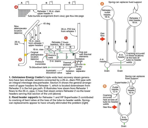
Ontelaunee’s HRSGs are triple-wide (three panels across as shown in Fig 1A), triple-pressure boilers. The horizontal centerlines of top and bottom headers are located just shy of 60 ft apart. Reheaters for these units are divided into two sections (Fig 2A)— Reheater 1 is the coolest, Reheater 2 the hottest (Fig 3). The two sections are connected by a 26-in.-diam heavily insulated P22 line located outside the boiler casing. The vertical section of this pipe includes an interstage desuperheater (Fig 1B).
As sketches 1B and 1C show, a 16-in. riser from each of Reheater 1’s upper headers connects into a nominal 30-ft horizontal section of the 26-in. pipe. A 90-deg elbow directs the partially reheated steam downward through an attemperator and via a second 90-deg elbow to a horizontal section of pipe running under the lower headers for Reheater 2. This segment of pipe is equipped with three 16-in. riser nozzles which direct the Reheater 1 outlet steam to the upflow Reheater 2 tube panels.
First significant damage to Ontelaunee’s HRSG pressure parts was found by an operator on rounds in fall 2007. The units were only five years old at the time. Wet insulation and a whisper of steam from the lower horizontal pipe section on Unit 2 indicated the possibility of a through-wall crack in the 26-in. line just downstream of the elbow.(Click thumbnails to enlarge images)
Inspection following shutdown of the unit revealed a 10-in. transverse crack at the top of the pipe; about 20% of the crack had penetrated the 1.2- in. pipe wall. Because the unit was needed, a 4-ft section of the pipe was replaced before conducting a root-cause analysis. One thing engineers knew for sure: Heat from GT exhaust gas was not a contributing factor because the pipe was outside the casing.
As a precaution, Dynegy had the lower-elbow area of the Unit 1 HRSG x-rayed the following February (2008) and found no indication of damage. Two years later (April 2010), a circumferential crack was found at the base of the weld connecting the elbow to the horizontal run of pipe on Unit 2.
Then in May, a circumferential crack was found on Unit 1 at the base of the weld at the top of the elbow. This finding confirmed that an engineered solution was required to address the issue. Several months later, a base-metal crack was noted on the 26-in. line for Unit 1 above the same elbow. During demolition, a bulge in the pipe wall was in evidence about 2 ft above the elbow.
Cracking of the 26-in. pipe connecting Reheaters 1 and 2 was not the only indicator of HRSG problems. Cracks also were found in the heat-affected zones of about a half-dozen P91 tube-to-header welds at the top of Reheater 2, Row 2. The OEM repaired five in fall 2008 with 18-in. stubs; a couple of tubes had been repaired earlier. Structural Integrity Associates Inc analyzed several tubes and concluded that creep fatigue was the cause. Three more tubes failed by the following spring (2009).
The OEM’s engineers believed water-quenching of the tubes was the root cause of the problem. Repair of the leakers in the middle tube bundle (Section B) during spring 2009 meant that the plant had taken two outages within a six-month period to correct the same problem. Clearly, this was unacceptable. But where was the water coming from? Sleuth work undertaken by plant personnel in 2010 would provide the answer.
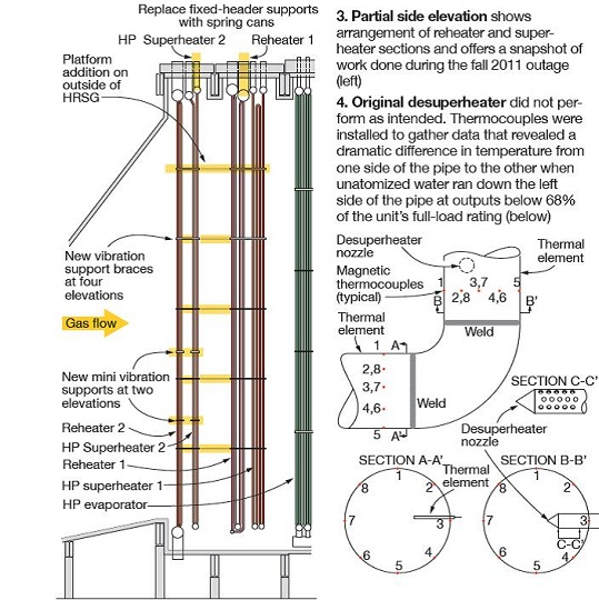
The only logical source of water was the probe-type attemperator with fixed-orifice nozzles oriented in the direction of flow. The plant’s O&M team, which works collaboratively to resolve issues, agreed with one of the mechanics in the group that the placement of magnetic thermocouples on the pipe surface above and below the elbow would provide at least some of the much needed data (Fig 4).
The idea certainly met expectations. Perhaps the most startling finding was that the external pipe surface on the left side (looking at Fig 4) could be as much as 400 to 600 deg F cooler than the right side, depending on plant output. Another important finding: When the plant operated above 68% of its full-load rating the temperature of the pipe was the same around the entire circumference—meaning all attemperator water evaporated.
Yet another important finding: Water that did not evaporate ran down the left side of the pipe, curled around the elbow, and remained near the top of the 26-in. horizontal pipe. Most of the free water was sucked up into Bundles C and B, the first two in the flow path and the ones seeing most tube damage from quenching.
Note that the drain arrangement for the 26-in. horizontal section shown in Fig 1C was not installed when the problems were occurring. Back then there was only one drain at the end of the pipe where Bundle A is located.
Fall 2011 outage
Replacing the vertical and lower horizontal sections of the 26-in. interstage reheat piping for both Units 1 and 2, together with the lower elbows, was the most significant boiler project undertaken during the fall 2011 outage, which also involved an HP steam-turbine repair requiring the cover to come off. OEC hired Bremco to complete other HRSG work, including the following:
-
-
Replacement of the reheat drain systems.
-
Change-out of the fixed upper-header supports on Reheater 1 and Superheater 2 with a spring coil support system.
-
Modification of some vibration supports for Reheater 2 and Superheater 2 tube bundles and the installation of additional supports.
-
 To maximize asset production, both units remained in operation during Bremco’s first week on site when its crew went through general safety and lock-out/tag-out training, installed hoists and rigging beams, set up staging and tooling, defined laydown areas, mobilized trailers and personnel, verified test reports for materials supplied by others. Dynegy took Unit 2 out of service first, leaving Unit 1 in operation while Bremco began work on all four tasks simultaneously.
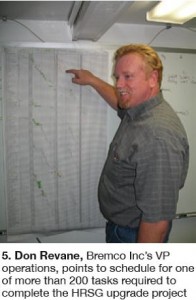
About two weeks later, Dynegy shut down Unit 1, allowing work on both HGSGs. Work ramped up on Unit 1 as it wound down on Unit 2, enabling the latter to begin operation before the Unit 1 work was complete. During the course of the outage, Bremco identified more than 200 individual multi-step tasks that required detailed planning to achieve Dynegy’s objectives. Revane, Bremco’s vice president of operations, points to the task list in Fig 5 that he used to direct the project from the company’s New Hampshire headquarters.
Revane estimated that planning, coordination of activities with Dynegy and N/E, relentless review of procedures before actual work was undertaken, safety and NDE initiatives, rigging plans, job-hazard analyses, qualifying vendors, etc may have required upwards of 20% of the contractor’s man-hours. The Bremco executive credited Dynegy and N/E’s appreciation of the work involved and their unflinching support as an underlying reason for project’s success.
To meet the schedule and budget goals of a large and complex boiler project, such as Ontelaunee’s, Revane stressed, it’s necessary to always have a Plan B so you can move a defined task in a different direction without delay, if necessary. Dynegy enabled a high productivity work environment by assuring an engineering response to all questions around the clock, the contractor continued. Revane and Site Superintendent Todt couldn’t remember a time during the outage that they had to wait more than half an hour for the answer to any question, no matter how complex it was.
This capability was enabled by Dynegy’s assignment of Plant Engineer Gassert as the “go-to” person for questions during the day and Ontelaunee’s Mark Vogt Jr at night. Terry Long led the re-engineering effort for N/E.
RH interstage attemperator, piping replacement
Removal of the poor-performing attemperator and associated 26-in. piping was first step in eliminating fatigue damage threatening the integrity of the interstage segment of the reheat system and returning it to as-new condition. A step-by-step plan for the demolition effort was developed by N/E. It included instructions on where to cut the existing pipe to enable removal of the vertical and lower horizontal sections; how to secure system components not being removed; where to install rigging lugs/shear tabs, or burn rigging holes required; how to attach clamps, hoists, and chains to the rigging beams, etc.
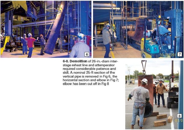
The vertical section was cut just below the upper elbow, at about mid length, and just above the lower elbow. Fig 6 shows one section of the vertical section, about 25 ft long and weighing between 4 and 5 tons, being lowered carefully in an area cordoned off to restrict personnel access. The top priority given safety resulted in an accident-free project.
The lower horizontal section and elbow, resting on custom-made carts, is about to be towed out of the plant (Fig 7), where the elbow was removed from the nominal 30-ft pipe for ease of handling (Fig 8).
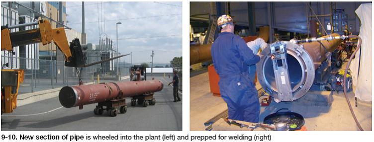
Demo complete, new pipe sections are brought into the plant (Fig 9) and prepped for welding. Fig 10 shows an E H Wachs clamshell prep tool machining a weld joint consistent with requirements of the ASME Boiler and Pressure Vessel Code. A Wachs field rep joined the Bremco team for this purpose because of the critical dimensioning required.
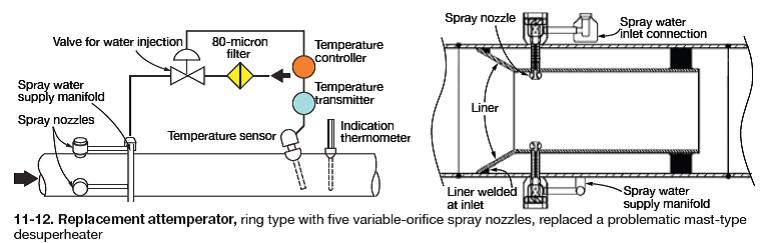
The desuperheater section, supplied with a spray-water connection and temperature element and transmitter, is located about 35 ft above where it was in the original design to maximize the time available for evaporation. A new platform was installed at the attemperator location, complete with lighting, to allow monitoring and maintenance access (refer back to Fig 3).The new interstage attemperator and piping, ordered by Dynegy, were installed by Bremco as directed by the current edition of the National Board Inspection Code. The vertical run of pipe was prefabricated in two sections, each about 25 ft long—the upper segment incorporating the spool piece for the attemperator, provided by Control Components Inc (CCI).
The attemperator installed at Ontelaunee, is shown in Figs 11 and 12. Five spray nozzles located 72 deg apart around the circumference of the desuperheater are piped into the ring manifold supplied with IP feedwater for attemperation. The use of variable-area spray nozzles assures efficient primary atomization regardless of steam flow. Borescope access is provided by the design to accommodate routine field inspections of internal condition.
The improved atomization offered by the new attemperator has met expectations to date. Maximum temperature differential across the pipe now is within 50 to 100 deg F at combined-cycle outputs down to the minimum load allowed by the plant’s emissions permit (perhaps 55% of rated capacity). Further, a temperature differential occurs only during significant changes in load.
The upper section of 26-in. pipe (note the attemperator spray-water ring at far end) is raised into place in Figs 13, 14. Fit-up of vertical members for welding is shown in Fig 15, fit-up of the lower vertical section and elbow is in Fig 16. Fig 17 shows Bremco welder Matt Gray installing the final weld cap on the joint connecting the two sections of vertical pipe. The P22 material is being welded with E9018-CM electrode with the line being held at the required preheat temperature of 300F.
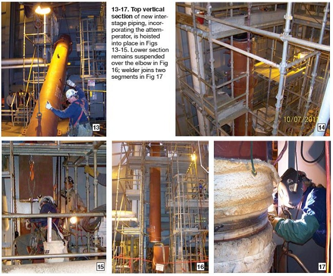
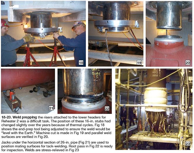
Fig 18 shows the E H Wachs field tech (right) and a Bremco employee preparing to prep the 16-in. nozzle for a Reheater 1 header. The nozzle came through the casing at an angle that required a skilled machinist to assure the weld would be “level with Earth.” In this case, fit-up blocks on the machining tool had to be modified to achieve the necessary result. Figs 19 and 20 show the actual machining and final alignment check, Fig 21 one of the jacks required to lift the pipe segment into position for welding.The biggest challenge faced by the contractor was prepping for welding the 16-in. risers connecting the horizontal pipe section to the lower headers (refer back to Fig 1C). Recall that the risers were cut to remove the original 26-in. pipe. The problem was one of alignment: The new horizontal section was purchased with nozzles in the exact position specified by N/E drawings; however, the riser stubs welded into the lower headers had moved from their original positions over time as material “worked” during start/stop cycles. All three of the riser weld joints had to line up within 1/8 in.
First step was tack welding, followed by heat treatment. The root pass for the riser serving Bundle C (Fig 22), typical of the critical welds made by Bremco’s Welding Superintendent Gary Martin, was manually done using the GTAW (gas tungsten arc welding) process, then checked by Dan O’Gara, certified welding inspector and Bremco’s field inspector for Ontelaunee.
The weld was x-rayed after the root and hot passes to be sure there were no indications before it was filled and capped. Post-weld heat treatment followed. Fig 23 shows electric resistance heaters and insulation blankets on elbow (near field) and riser welds. A second x-ray was taken after the PWHT step. The third-party x-ray technicians told Bremco site personnel they were the cleanest welds they’d ever seen.
The drain system for Reheater 2 was upgraded to reflect operating experience as well as changes to the ASME Boiler and Pressure Vessel Code made in 2007 to accommodate the special needs of HRSGs. These requirements are detailed in Part PHRSG of Section I.Drain modifications
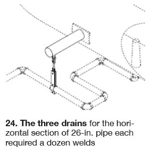
As noted earlier, Reheater 2, as designed, had only one drain at the far end of the horizontal section of 26-in. pipe. It was ineffective because thermal expansion caused water in the pipe to move away from the drain, not toward it. The new arrangement shown in Fig 1C has three 2-in. drain pipes. The automated drain system, controlled by thermocouples in the drain pot’s water column, normally sends any water collected to the blowdown tank. Alternatively, the water can be diverted to the oily water separator.
The drain system is not as simple as you might think. Fig 24 shows the layout required to accommodate piping movement. Each of the three drain lines requires a dozen pressure welds. The 2-in. ball valves used in this system to assure positive shutoff were supplied by Conval Inc.
Spring cans replace rigid supports
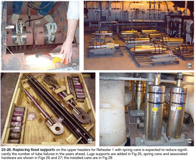
A new coil support system was designed by N/E to prevent cracking caused by differential expansion of tube rows in both HP Superheater 2 and Reheater 1 (Figs 2A and 2B). Several bent tubes in both of these heat-transfer sections had suffered cracks at the toes of their tube-to-header welds. By allowing header movement, the added stress caused by differential expansion between tube rows can be minimized. N/E developed a comprehensive procedure for demolition and installation, along with necessary drawings.
Two spring cans were installed per header following the installation of lug supports (Fig 25). Note that the lugs are tacked into place with a spacer installed to make sure the lugs stay parallel during weld-out. Spring cans are mobilized alongside the kettle boiler (Fig 26) with the necessary hardware (Fig 27). Spring cans as installed are shown in Fig 28.
N/E designed a new restraint system to supplement the vibration supports provided with the tube bundles (alternatively coils or harps) that comprise Reheater 2 and HP Superheater 2. The original supports suffered extensive damage from turbulent gas flows and repairs/modifications were necessary. The redesigned system helps protect the coils from excessive movement and vibration.Tube-bundle restraint system
The work is highlighted in Fig 3. The specifics:
-
-
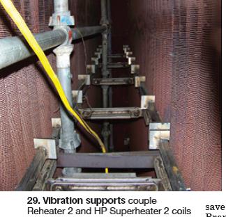
Demo the three lowest levels of vibration supports in each coil comprising Reheater 2 and HP Superheater 2. Replace with newly designed supports (Fig 29).
-
Add two levels of mini vibration supports to all Reheater 2 and HP Superheater 2 panels.
-
Add four levels of bracing between Reheater 2 and HP Superheater 2 and between HP Superheater 2 and Reheater 1.
-
Note that Reheater 2 and HP Superheater 2 heat-transfer surfaces are 17 in. apart fin tip-to-fin tip; HP Superheater 2 and Reheater 1 are 4 ft apart.
Detailed step-by-step instructions were provided by the OEM to assure that vibration supports would be installed correctly. To save time on this portion of the work, Bremco, N/E, and Dynegy personnel together developed a method for installing the new supports without having to cut through the casing as originally believed. The three parties, working collaboratively, allowed participants to voice their opinions before final decisions were made—benefitting all. CCJ