


Enhanced enclosure cooling-fan control
Best Practices Award
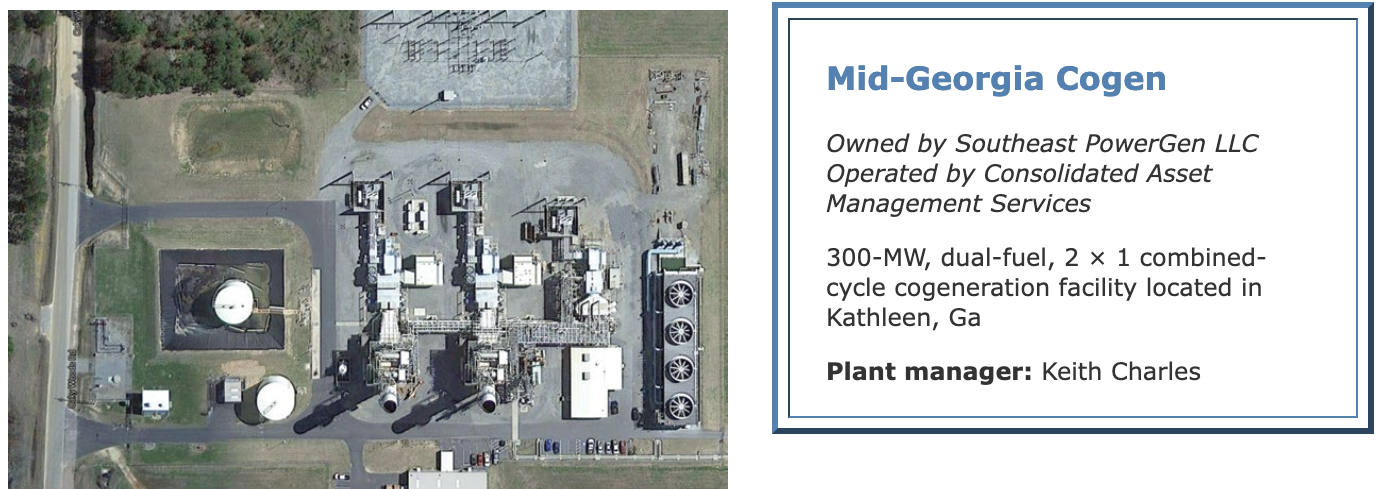
Challenge. The air flow inside each enclosure at Mid-Georgia Cogen is controlled by four roof-mounted fans above the compressor section of the gas turbines, about midway to the combustion section. The fans are mounted in a straight line across the top of the enclosure perpendicular to the turbine shaft.
Air from the two outboard fans is directed downward to the floor and to the rear of the enclosure. The middle two fans, mounted directly above the compressor section, blow cool air directly on top of the compressor and combustor sections. Hot air is exhausted from the enclosure via two large ducts in the roof at the exhaust end of the turbine.
 By OEM design, the four enclosure cooling fans were operated in groups of two by two Mercoid thermostats. In addition to being expensive, the thermostats were very unreliable and caused erratic vent-fan operation. Routinely, the thermostat failed to start the fans when required. Result: High enclosure temperatures would damage various turbine control components—such as disc-cavity actuators, fuel-gas transmitters, quick exhaust air valves, etc.
The fans also might continue to run when they should have been off. This caused rapid and uneven cooling of the turbine after shutdown, which is conducive to high vibration during the following dispatch. At times, the thermostats would cause rapid cycling of the fans, causing the breakers to trip. To compound the issue, fan operational status was not fed back to the DCS so that the only way to detect incorrect fan operation was for an operator to observe the fans locally in each GT enclosure.
Another serious safety-related issue: If there was indication of combustible-gas build-up in the enclosure, there was no way to ventilate it except for having an operator go to the turbine electrical package and start the vent fans locally from the MCC.
Solution. Plant personnel decided that cooling-fan operation must be automated and controlled from DCS and that the DCS also had to provide the CRO feedback and the ability to operate the fans remotely. To this end, the Mercoid thermostats were removed and replaced with thermocouples.
Two additional T/Cs were mounted on each side of the enclosure ceiling, between the fans and the exhaust ductwork, to provide feedback to the control room operator. Controllers were installed in an empty MCC bucket to allow fan control from the DCS, and auxiliary contacts were wired to the DCS to provide feedback of fan operational status.
DCS logic then was implemented to automatically start the two outboard fans when (1) either the generator breaker closes, (2) the enclosure temperature is greater than 90F as measured by one of the wall-mounted T/Cs, or (3) if the combustible-gas concentration reaches 10% LEL. The outboard fans stop automatically about an hour after all of those conditions clear.
Control logic starts the two inboard vent fans when the enclosure temperature hits 95F or the combustible-gas concentration reaches 15% LEL. Once the high-temperature and/or high-gas-concentration conditions clear, the fans will automatically stop after operating for another two hours. Either set of fans can be started and stopped manually from the control room or allowed to run until they time out.
The control scheme, among other things, assures that the outboard fans are the first to start and last to stop thereby reducing the time that the inboard fans blow cool air directly on the top of the compressor and combustor sections of the turbine.
The four T/Cs in the enclosure are now monitored on the GT control screen. They also sound audible alarms to alert the CRO of high enclosure temperature. Vent-fan operational status also is indicated by alarm and by indication on the turbine control screen.
Results. By controlling the fans with the DCS logic instead of by failure- prone thermostats, the plant gained direct control of the fans and no longer experiences high vibration during unit starts. In addition, GT operation is more reliable because there are fewer failures from overheating of control components inside the enclosure.
Thirdly, by having the fans under DCS control, they are started automatically when a buildup of combustible gas is sensed. Finally, the CRO now has remote control and indication of fan operation, allowing early identification and correction of problems before they become safety or reliability issues.
Project participants:
The entire plant staff
Verify proper operation of protection systems
Best Practices Award
Challenge. The steam turbine/generator (STG) at Mid Georgia Cogen relies on two TACHPAK3s (AI-Tek Instruments LLC) for two of the trip-request signals in a two-of-three electrical overspeed-trip (OST) scheme. During a routine overspeed monitor test and calibration of the OST system, an I&C technician discovered both TACHPAK3s in the “configuration” mode.
In this mode, the instruments will not generate a trip signal regardless of the input signal. With both TACHPAK3s so configured, the electrical OST system is rendered inoperable because the logic will never see more than one trip indication.
This leaves protection from a potentially catastrophic failure of the STG from an overspeed condition dependent solely upon the single mechanical OST trip mechanism. It could not be determined how long the TACHPAK3s were in this mode. It is assumed that they were this way for an extended period during which time the turbine had been operated as dispatched.
This situation also made it apparent that a failure of two speed channels and/or the TACHPAK3s monitoring them could occur, making the electrical OST system inoperative without any indication at all to the operator.
Solution. Staff found that there was one unused input channel available in each TACHPAK3 that could be used for a supervisory signal. We fed the speed signal into that channel and configured the alarm set-point to close a normally open electrical contact below 200 rpm.
If the TACHPAK3 is operational, the contact will open as the turbine passes through 200 rpm during a unit start. Plant personnel then implemented logic such that if the contact for this supervisory function remains closed as the speed continues to increase, an alarm is generated alerting the operator as to which of the two speed pickups or TACHPAK3s has failed long before the turbine reaches the normal operating speed of 3600 rpm.
Results. A single or dual OST protection string failure can now be detected and corrected immediately. Recall that the original arrangement allowed the system to be operated with no electrical OST protection and with no indication of the lack of protection.
Operators are now confident they will be alerted to take appropriate action long before an over-speed condition could result in catastrophic failure of an unprotected turbine/generator set. This modification has the potential of saving the plant from the extremely unsafe and costly failure were an overspeed condition to occur.
Project participant:
Danny Luker
GT air leakage test procedure
Challenge. The 501D5A has many air-operated solenoids and actuators that control valves and other components critical to turbine operation. The lifecycle of a solenoid valve or actuator varies based on product quality, frequency of use, and compressed-air quality. Regarding the last point, regular maintenance of air compressors and dryers is critical to reliable operation and long life of air-powered components.
With no air-system testing procedure and no way to predict when failures could occur, turbine reliability, in standby or online, is compromised. On several occasions, solenoid-valve failures or air leaks delayed dispatches, causing auto-unload conditions and unit trips.
Solution. A monthly preventative maintenance procedure was developed to test the instrument air system for leaks on all air-operated equipment critical to turbine operation. The procedure provides detailed instructions for performing the air-leak test on various solenoids for the fuel systems and other specified valves.
All critical components that use the GT compressed-air system are checked. Procedure includes inspection and testing of vent-fan and exhaust dampers, lube-oil temperature control valve, HP and LP bleed valves, disc-cavity control valves, fuel gas and oil overspeed trip valves, water injection control valves, pilot and main gas-vent valves, and the PS&G cabinet.
Results. Since implementing the procedure, the plant has not had any delayed dispatches or unit trips attributed to the turbine compressed-air system or components. Also, plant operators have become very familiar with the various components and their control logic.
Several problems have been identified while performing the air-leak test that could have potentially delayed dispatches or caused unit trips. In one instance an operator found a disc- cavity control valve operating incorrectly because of a positioner problem. Another time the pilot-gas isolation valve solenoid was found inoperable. Examples of still other problems identified during the air-leak test include: inoperable blowdown valve on the air receiver tank, leaking LP bleed-valve solenoid, and inoperable vent-fan- and exhaust-louver solenoids.
Project participants:
The entire plant staff