


Collaboration, focus on constructability result in efficient design meeting challenging schedule
Best Practices Award
Challenge. The collaborative project team successfully overcame numerous design and logistical challenges, the primary one being schedule. The project was originally conceived by the owner to be a generating facility with a different configuration, at a different location, and with different major components from different manufacturers. The tight site impacted design parameters and necessitated modifications. TVA’s engineer, URS Corp, was tasked to incorporate these changes without negatively impacting project schedule.
This project originated as a conversion of three existing simple-cycle gas turbine/generators (GTs) into a combined-cycle plant. Electric-system requirements dictated relocation of the project to a higher elevation and a different seismic zone andrequired dual-fuel GTs so the plant could use gas or distillate. The design had to allow operation in simple cycle, only without sharing ancillary equipment with the remaining combined-cycle equipment. Other design changes from the original included the source of makeup water and operation in simple- or combined-cycle modes.
The project required a complex environmental permit to incorporate the combined cycle into the existing permits for the adjacent coal plant. The National Pollutant Discharge Elimination System permit is shared with the active coal plant on the same site and was revised to include one additional outfall. The waste generation status also is shared with the active coal plant.
Solution. Previously, the design team had performed extensive engineering and procurement for the owner for the combined-cycle conversion project at the original location. That project was deferred and the engineering and material were redeployed for the current project. This project used state-of-the-art technology with a mix of new and gray-market components.
To ensure that the schedule and budget remained on track, the engineering team verified that equipment previously purchased would meet the new heat-balance parameters and incorporated new GTs into the design. The change in engines required additional design adjustments. Ultimately, the team was able to use 50% of the original project design and all of the equipment previously purchased, making efficient use of work already performed.
International collaboration was instrumental in overcoming design challenges. Engineering staff in Romania supported their US counterparts, working more than 40,000 man hours on this project. Sevier was one of the first deployments of Smart Plant P&ID and Smart Plant Instrumentation for the engineering team, allowing for efficient and timely interface between mechanical/piping and I&C team members.
Use of electronic eRooms for document management and collaboration allowed for timely transmittal of engineering drawings and documents, as well as the submission and subsequent return of shop drawings among parties. Communication among the home office, engineering, and field construction staff ensured design constructability and fast resolution of any issues.
Site constraints required innovative design approaches. Because of space constraints and constructability issues, a substantial number of electric cables had to be run above ground on tray racks, in lieu of using an underground duct bank or tunnel.
Successful accounting of air emissions between the coal and combined-cycle plants is complex because of the three HRSG stacks for normal operation and the three bypass stacks for simple-cycle service. The shared air permit utilizes a ledger to track when and where all emissions originate across the two plants.
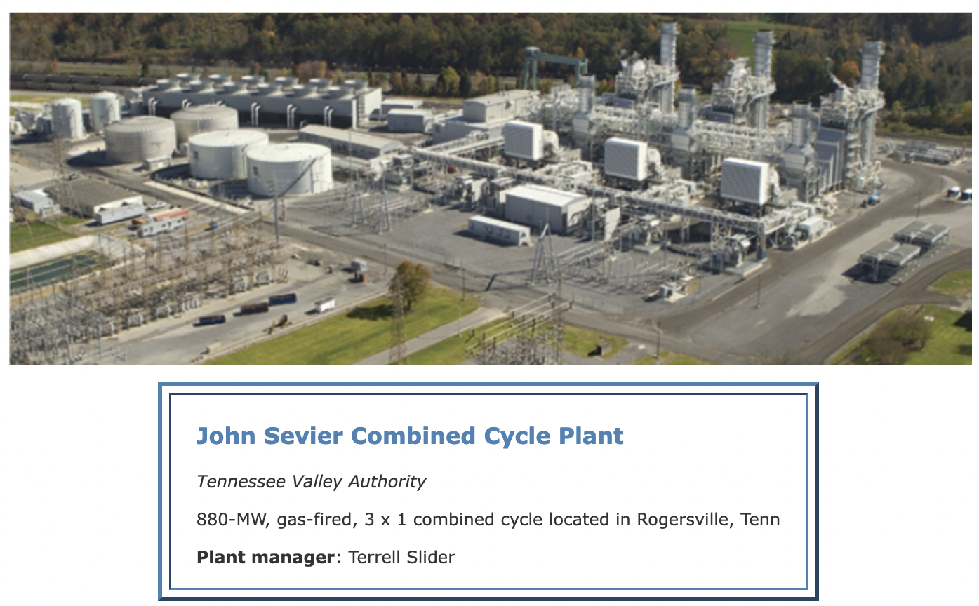
Results. The owner/operator’s mission is to be a leading provider of low-cost, cleaner energy by 2020, and the 880-MW John Sevier Combined Cycle Plant helps significantly in that regard. It operates at high efficiency, minimizes emissions, and offers optimal flexibility for meeting peak demand. The project, which finished a month early and $30 million under the original $820-million budget, is the owner/operator’s lowest-cost, fossil-fired generating plant.
The project team successfully implemented all of the required modifications while meeting project milestones and holding costs well under budget. Result: The owner has a reliable generation source in northeast Tennessee.
The project uses three GE 7FA.04 dual-fuel GTs, the first of this generation to be tested and commissioned. The plant is also equipped with a Toshiba 400-MW steam turbine/generator and three Nooter/Eriksen heat-recovery steam generators. The latter have duct burners and catalyst systems for NOx and CO emissions control. The plant also is equipped with bypass dampers and stacks to allow either simple- or combined-cycle operation. This capability was engineered into the plant to support the changing demand profile for the region and to provide maximum reliability.
 Project participants:
Mike Hoy, senior manager, NUS construction projects, TVA
Bill Lam, URS
Bob Schad, URS
Bob Romanelli, URS
Tom Brown, URS
Rob Chiavaro, URS
John Moore, URS
Adapting vent stack design to handle flashing of process-steam drains
Best Practices Award
Challenge. Headers serving steam systems operating at four different pressures must be drained to prevent condensate from entering the steam turbine during startup, shutdown, and/or other modes of operation at this combined-cycle plant. Piping for each steam system is routed in a pipe rack that extends more than 450 ft.
Low-point drains located strategically along the piping runs collect condensate in drip pots. Each drip pot relies on an air-operated, fail-closed drain valve controlled by either a thermocouple or level switch to discharge condensate. A total of 72 drain valves must be organized and controlled to perform this task properly.
Drain tanks typically are used for collection of these drains. But on this project, vent stacks were specified in lieu of tanks. The challenge for engineers was that the design of the vent stacks did not provide adequate controls and the necessary heat transfer to allow their proper operation.
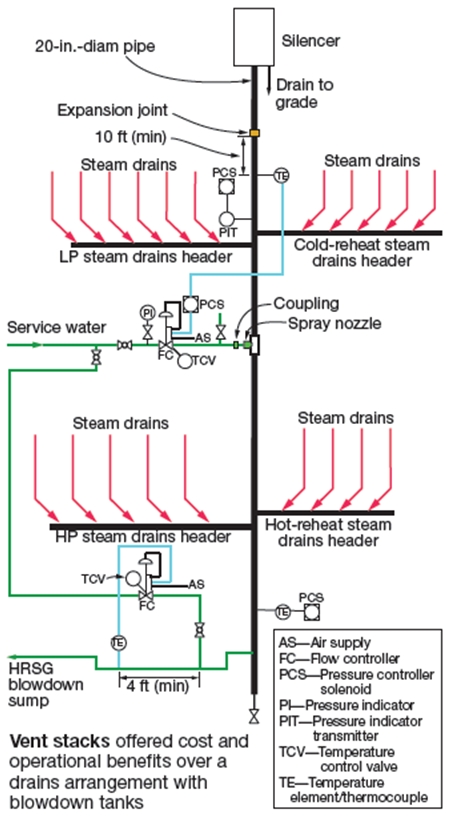 Solution. Three locations along the pipe rack were identified to support the vent stacks and allow the drains to discharge the flashing steam and water safely. The various drains, grouped by steam pressure, were connected to manifolds, which discharged to vent stacks sized to accommodate the expected steam release. Steam passes through a silencer before discharge into the atmosphere (figure).
Each vent stack, constructed from heavy-wall alloy-grade pipe with a cap at one end and a silencer and expansion joint on the other, was supported to allow proper thermal growth as steam was vented. To minimize the length of each drain pipe, drains were routed to the closest vent stack. Thus each vent stack did not contain the same quantity of drains nor release the same quantity of steam/condensate.
During plant startup, engineers determined that the pressure within the vent stack exceeded the design pressure of the system, and that there was insufficient heat transfer to lower the exhaust steam temperature to an acceptable level, even though the service-water temperature control valve was wide open.
To manage temperature and pressure within the vent stack, the system was modified to introduce service water through a spray nozzle, which created a fine mist into the venting steam to help reduce the temperature within the stack as it reaches the design limits of system. A pressure transmitter installed a sufficient distance from the inlet to the silencer monitors the internal pressure and controls the quantity of drains discharging into the vent stack should the pressure approach expansion-joint design limits.
Any condensed steam and excess spray water would be routed from the vent stack and collected in a sump for use as cooling-tower makeup. Additional spray water and a thermocouple are connected to the drain from the vent stack, thereby controlling the temperature of hot water/steam discharging to the sump, protecting the sump pumps from damage.
Results. Normally, the steam system drains are discharged to blowdown tanks—or, in this case, vent stacks—and the drains are kept open during the startup for a substantial period of time until the piping is heated and the steam shows signs of superheat. This requires over-sizing of equipment (blowdown vessels, silencers, supports) in an effort to discharge steam and water, which also results in the loss of large quantities of steam (that is, more make up required).
For this project, use of piping as the vessel to discharge the flashing steam and condensate was more economical than designing and fabricating a blowdown vessel. This approach also took less space and required no foundation.
By monitoring both the temperature of the steam being discharged and the pressure within the vent stack, the operator is able to control the quantity of steam being discharged and stay within the design parameters of the equipment. This minimizes the loss of steam, shortens the duration to generate steam, and helps reduce capital cost.
Project participants:
Mike Hoy, senior manager, NUS construction projects, TVA
Robert V Chiavaro, URS
Voltage-class evaluation results improve cost-effective performance
Best Practices Award
Challenge. Standard industry practice suggests that 200-hp motors are the breakpoint between low- and medium-voltage service to mitigate voltage-drop concerns. The cooling-tower fan motor rating for each of the 12 cells at John Sevier Combined Cycle Plant was 200 hp. Cooling-tower vendors typically would suggest 480-V motors for these fans.
However, Sevier was designed with two circulating-water pumps powered by 4.16-kV motors supplied from the same electrical room. Given the high 480-V demand and the proximity of 4.16-kV power, the project team evaluated use of 4.16-kV motors for the fans.
Solution. URS estimated the cost of each voltage-class configuration on an equipment and labor basis only. The engineering analysis and resulting study showed that the medium-voltage configuration would be preferred from both an operational and capital-cost standpoint. Therefore, medium-voltage motors were recommended.
Employing the medium-voltage system offered several advantages. Overall, there are fewer cables to be installed, less equipment to be maintained, and the 4160-480-V transformers were eliminated. One medium-voltage motor control center was provided in lieu of an additional low-voltage double-ended power center.
Results. Based on the evaluation findings, medium-voltage motors were installed to drive the cooling-tower fans. The power distribution system meets the owner’s performance requirements and reduces costs. The successful implementation of this best practice suggests that when there are multiple loads of 200-250-hp motors, evaluation of the voltage selection is prudent and a medium-voltage system may be more cost-effective; plus, it offers a more robust design.
Project participants:
Mike Hoy, senior manager, NUS construction projects, TVA
Robert Schad, supervising electrical