


Efforts to locate, repair damage from spark erosion advance
Most gas-turbine user groups devote at least a few hours at each conference to presentations and Q&A on generators, with much of that time focused on air-cooled units installed at combined-cycle, cogeneration, and simple-cycle plants over the last 15 years or so. It’s rare that a meeting passes without meaningful discussion of spark erosion (SE) and partial discharge (PD)—phenomena associated with air-cooled machines.
These subjects also have been addressed in recent CCJ articles. Access “There’s nothing generic about generator failures” and “Diagnosing partial discharge, spark erosion” in the 2011 Outage Handbook.
New methods for condition assessment and repair of air-cooled generators were included in a presentation at ASME’s 2011 Power Conference in Denver, last July, by John Jensen, PE, senior generator design engineer, and Alfred Laforet, manager of generator products, Alstom Power Inc, Midlothian, Va. The complete paper, “Turbogenerator spark erosion inspection and repair,” POWER2011-55337, is available through the society.
The promise of the new methods described by Jensen and Laforet: A more objective and more accurate condition assessment than previously possible, one conducive to selection of the optimal repair for any given generator. The duo stressed that repair options short of a complete rewind are now available to restore the normal life expectancy of a generator, or to at least extend the machine’s life until more extensive repairs can be planned.
The work by Alstom to mitigate spark erosion in generator stators identifies with two SE phenomena—one caused by capacitive slot discharges (partial discharges), the other by vibration sparking. The latter, a known effect in high-voltage machines, is conducive to rapid and severe insulation damage. Vibration sparking, the authors said, is distinct from the PD effect caused by interruption of current paths. Note that at least some other experts in the field are known to use SE and vibration sparking interchangeably.
Background. Jensen and Laforet began by providing valuable perspective on the damage mechanisms. Spark erosion, they told attendees, was first identified in the 1960s as generator manufacturers moved away from the use of asphalt-based insulation systems to epoxy resins. Asphalt insulation systems by their nature were prone to significant swelling during thermal cycling; this ensured that the bars maintained good contact with slot walls.
The transition to epoxy insulation systems required the use of semi-conductive side fillers in the slots to maintain tight contact between the bars and slot walls. Compared to asphalt, epoxy insulation systems expand minimally during thermal cycling. Improper fit-up of side fillers promotes looseness in the slots, allowing the bars to vibrate, thereby enabling insulation wear and arcing associated with capacitive slot PD and vibration sparking.
The science of spark erosion
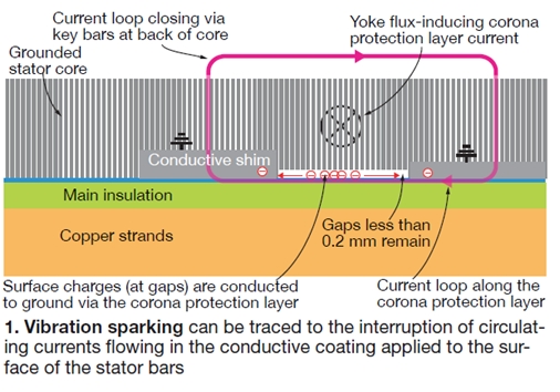
Vibration sparking, the co-authors explained, has its origin in the interruption of currents flowing in the conductive coating (slot corona protection) applied to stator-bar surfaces. These surface currents are created by magnetic flux in the stator yoke and are a normal occurrence in all generators.
However, by design, these currents normally are dissipated from the bar surface to ground through contact between the stator bars and core. The conductive corona protection coating on the surfaces of the bars, and the conductive filler material used to wedge the bars tightly in their respective slots, assure good electrical contact to the core (ground, Fig 1).
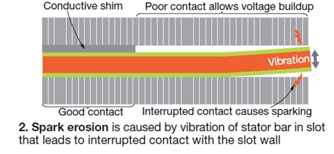
Vibration sparking occurs when the currents flowing in the corona protection coating are interrupted because of the movement of the stator bars relative to the slot wall. These axial currents flow from one point of contact with the slot wall to another via the coating. If one of the contacts opens to interrupt the current then there is a risk of sparking—depending on the distance between contacts and the magnitude of the current (Fig 2).
This type of sparking can occur only when stator-bar vibration exists. One of the factors influencing arcing is the level of the induced voltage in the loop built along the corona protection layer via contact points to the core and the key bar (refer back to Fig 1). Thus the resulting current depends on the induction design data for the generator, the axial resistance of the bar corona protection layer (Raxial in ohms/meter), and the lateral resistance (so-called contact resistance) of the corona protection layer (rlateral in ohm-meters). The combination of the axial and lateral resistance is known as the contact coefficient, defined as:
![]()
When a stator bar is installed and wedged in the slot with poor side filling, or if there are inconsistencies in the slot geometry, voids or gaps are created between the bar surface and core iron. These voids, or gaps have electrical and mechanical consequences. For example, they reduce the contact coefficient when the contact resistance of the corona protection layer increases.
Additionally, without appropriate mechanical support, stator bars can vibrate in the slot, creating conditions conducive to vibration sparking. Operating time also impacts the risk of SE occurring.
High currents in the corona protection layer of the stator are exacerbated when material ageing and high temperatures contribute to reduced electrical resistivity of the conductive coating on the stator bars. The result is a decrease in the axial resistance of the corona protection layer. Bar vibration in the slot can be amplified over time by the loosening of radial slot wedges designed to maintain radial pressure on the bars and dampen vibration.
What the foregoing suggests is that the contact coefficient is a good indicator of vibration sparking risk because it accounts for both poor lateral contact between the bars and slot wall (risk of bar vibration) and low corona protection layer resistivity (risk of high currents in the corona layer).
Jensen and Laforet also pointed out that the phenomenon of vibration sparking, unlike capacitive partial discharge, is not restricted to high-voltage bars. It can occur anywhere in the winding because the factors that cause it—slot vibration, poor lateral contact, and low resistivity of the corona protection layer—can be found anywhere in the winding.
Over time, the co-presenters continued, destruction of the corona protection layer through vibration sparking and the abrasive effect of bar vibration will, at the least, lead to capacitive discharges on bars exposed to highest voltages. They concluded the theoretical portion of their presentation with the observation that if sufficient damage is caused to the corona protective coating, SE phenomena, vibration sparking, and capacitive discharge can become superimposed on each other.
Inspection methods
There are several methods that can be used to inspect for the presence of spark erosion in a generator: visual, direct measurement of the contact coefficient, and partial discharge analysis.
The use of multiple inspection methods was suggested by Jensen and Laforet to allow the best possible understanding of stator-winding condition. Here’s what you should know about each of them:
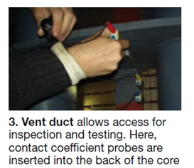
Visual inspection is the primary method used to inspect for SE. Typically, a borescope is used to view the exposed surfaces of stator bars visible at the core vent-duct locations (Fig 3). This can be accomplished from outside the core or from inside the bore of the core.
Visual examination provides a qualitative evaluation of the bars and offers evidence of their relative condition. It does not provide a fully objective analysis of stator-bar condition. It also restricts the analysis to the areas of the stator bars directly visible in the vent ducts.
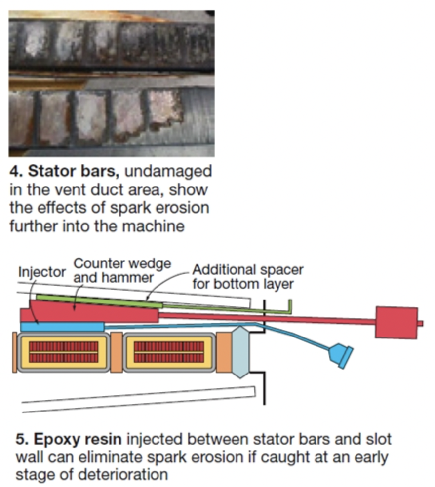
Experience suggests that the nature of spark erosion is such that even if there is no visible damage on the bars at the vent-duct locations damage may already exist between the bar and the slot wall (Fig 4).
Measure contact coefficient. This technique, developed by Alstom, is based on the injection of a current in the conductive coating on the outside of the stator bar and measurement of the resulting voltage distribution between the bar surface and the slot wall at several points along the bar in close proximity to the injection point.
How it’s done: Several probes are inserted through adjacent vent ducts to contact the sides of the stator bar. The voltages obtained are used to calculate the axial resistance of the conductive coating of the stator bar and the contact resistance between the coating and the slot wall. Having these data, the contact coefficient can be calculated.
Jensen and Laforet said thorough evaluation of generator condition requires calculation of the contact coefficient using data taken from at least three axial locations along the bar length of every accessible bar. They added that, based on Alstom’s experience, values of alpha greater than 8/m are indicative of good conduction between the stator bar and the slot wall and are expected for new windings.
Contact coefficients of 5/m or higher are normal for generators that have operated for a substantial period of time and have little risk of spark erosion. As alpha values decrease below this level, there is an increased risk of vibration sparking damage.
Partial discharge analysis also can offer clues as to whether any given generator suffers from SE. PD sensors normally are connected close to the high-voltage terminals of the generator in the isophase bus. Reason: PD activity associated with capacitive discharge within gaps is found in stator bars of a particular voltage level.
These sensors normally are used to measure the partial discharge effect, which is caused by the charging of defect locations (voids) with high voltage. Recall that vibration sparking can occur anywhere in the winding. When it occurs in the high-voltage bars, it normally is difficult to detect because it is masked by the capacitive PD activity that exists there.
However, the addition of a high-capacitance PD sensor at the neutral point, which can see all three phases from the neutral side, permits reliable identification of vibration sparking signals if such defects exist close to the neutral point. They can be seen clearly without interference from the PD signals associated with the high-voltage bars.
Repair options
There are several repair options to consider if you have a generator afflicted with spark erosion, including these:
- When SE damage is at a relatively early stage, it can be arrested by injection of a special conductive epoxy resin into the area between the stator bars and the slot wall to fill gaps conducive to spark erosion (Fig 5). Once the epoxy cures, it prevents bar movement and re-establishes electrical contact between the surface of the stator bar and the slot wall.
Stator windings so repaired at an early stage should have a normal lifespan, the speakers said. If the epoxy solution is applied at a more advanced stage of slot sparking damage, it should extend the life of the existing winding, subject to monitoring, to that time when proper repairs can be made. - Selective replacement of conductive slot side filling (primarily on top bars) can minimize slot looseness and poor conduction of the stator bars to the slot wall, thereby eliminating the root cause of spark erosion. New wedging methods can be used to increase the radial load applied to the stator bars, reducing the vibration of stator bars in the slot.
- When windings have already experienced extensive damage and inspections indicate their continued deterioration, a complete rewind is your only option. Important to remember is that your rewind must address the root causes of vibration sparking to prevent damage to the new winding.
Also, keep these lessons learned/best practices in mind:
- Carefully install stator bars with conductive side filling to minimize any gaps between the bars and the slot wall.
- Be sure all components in the slot are made of conductive materials, or have conductive coatings, to maximize the area for conducting stator-bar surface currents safely to ground.
- Maintain conductive materials and coatings at a sufficiently high level of resistivity over time to dampen the development of high surface currents that would exacerbate vibration sparking were bars to loosen.
- Insure slot wedging creates a high radial pressure to the bars to minimize vibration and ensure good contact between the stator bars and the slot bottom. The latter is particularly important because this is one of the primary paths for conducting stator-bar surface currents. CCJ