


Inline repair saves 9-chrome HP stop/check valve
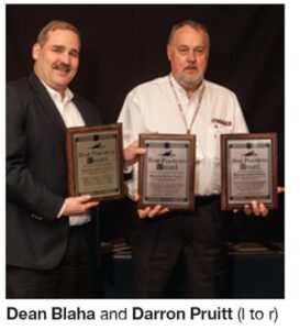
Best Practices Award
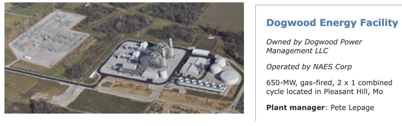
Challenge. Dogwood Energy Facility was experiencing internal leak-by on a 12-in. stop/check valve in the high-pressure (HP) steam system. The valve was opened with the expectation of needing to perform valve plug and disc machining and lapping to resolve the leak-by issue.
However, on disassembly, personnel discovered that the valve seat had cracked (Fig 1). The failure mechanism was differential expansion—that is, the Type-316 stainless steel seat and 9-chrome valve body were growing and contracting at different rates. The valve was reassembled and run as found until a suitable plan could be established to facilitate the repairs.
Solution. The plant considered three ways to deal with the issue, each with its benefits and detractions:
• Repair the valve according to the valve manufacturer’s recommendation.
• Replace the valve with a new valve.
• Perform an inline repair.
The valve manufacturer’s recommendation for repair involved cutting the valve out of the pipe and lowering it to the ground, through structure, from an elevation of 85 ft. The valve would then be shipped to the repair facility; a minimum of eight days was required for proper machining and heat treatment. The valve would then be returned to the site, lifted back up into position, and welded back into the steam line.
Next, when the valve was back in place it was important to maintain proper piping alignment to avoid creating damaging stresses. Alignment dogs would have to be welded to the piping and valve. To do this properly would require extensive heat treatment since the valve and piping are both 9-chrome material. Lastly, welding the valve back in the steam line would require the proper weld procedure for 9-chrome material. The estimated duration to perform this repair was 20 days at a total cost of about $165K.A couple of logistical challenges: Cutting the valve out of the line and welding it back into place presented issues, but they were not insurmountable. Examples: Would it be better to use a crane to lower and lift the valve or would a tugger be more cost effective and perform better given its location? (2) There is piping and structure overhead, but maybe it would be better to raise the valve out of the structure, then swing to an open area and lower the valve to the ground.
The next option was to replace the valve with a new one. The advantage of doing this was that the valve could be delivered to the site before the outage began so that as soon as the original valve was cut out and lowered to the ground, the new valve would be lifted into place and welded in the pipeline. With the exception of the duration of time needed for shipping the valve to a repair facility and shop repairs, this option posed the same problems as the manufacturer’s repair recommendation.
Bids for a new valve were obtained from three different manufacturers; the average cost was $208K. Field work was estimated at 10 to 12 days, including the time to perform the work and allow for proper pre- and post-weld heat treatment.
 The last option on the table was to perform the repairs with the valve inline. There were inherent advantages to performing the work by this method. However, there was one major challenge: Finding a company that could do the work in a satisfactory manner. The inherent difficulty with the inline repair alternative was that the existing seat would have to be removed and welded back in through the throat of the valve as opposed to the back side of the seat in the steam line.
Machining the seat out should not pose a problem, but once again, procedures to weld the seat back in would require proper pre- and post-weld heat treatment. This would mean holding the valve at approximately 450F while the seat was welded into place. The seat pocket is located about 32 in. down inside of the valve throat. This is beyond—or at the limit of—an arm’s length at shoulder depth, which would preclude the technician from being able to look down inside of the valve while welding.
Even if the seat pocket were reachable, the technician’s hand and arm would be exposed to a temperature of 450F while welding. Robotic welding would be difficult because of the temperature environment as well. The first contractors consulted all recommended welding at the end of a stick and using mirrors.
After an exhaustive search, plant personnel found a repair company that had developed a water-cooled system for a robotic arm capable of welding and machining at the temperature required to do the work. The work was estimated at 11 to 12 days working around the clock; the cost would be approximately $188K.
The plant did not have an outage period scheduled for 2012 which would allow for 20+ days of downtime, so anything beyond a scheduled 10-day outage would make the plant unavailable for commercial operation. Cost, impact to the system, and timeline all pointed to performing the inline repair.
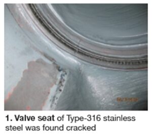
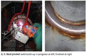
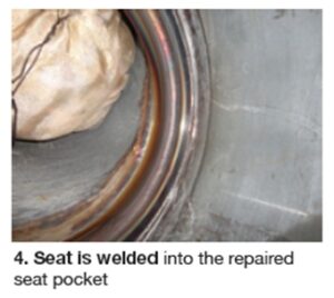
Once the valve was opened and the seat was machined out, it was determined that the seat pocket would need to be built up by weld repair, and then machined back to within spec (Figs 2, 3). After that was done, the seat could be inserted and welded in (Fig 4). The job went according to plan with exceptional results.
To minimize the chance of future failure of the seat from differential expansion, the valve manufacturer was consulted and said it was acceptable to replace the stainless seat with one of F91. This would match the material composition of the valve body.
Results. The project came in on time and well under budget with a final dollar amount of approximately $160K. There was zero impact to the schedule and system because the valve remained inline, thus minimizing the problems associated with line spring and subsequent piping alignment.
The piping was plugged using FME (foreign material exclusion) devices, and upstream and downstream borescope inspections were conducted prior to valve reassembly. Finally, the repair was completed within the scheduled outage and no revenue was lost because of unavailability.
Project participant:
Glenn Brons, maintenance coordinator
Management training for day-shift O&M technicians
Best Practices Award
Challenge. Develop a workforce capable of successfully assuming managerial roles.
Solution. Create a program to advance existing employees through hands-on exposure. In late 2012, Dogwood Energy Facility launched its “Day Shift O&M Technician Program” (DSOM) which uses a staff of five O&M Technician-A/Control Room Operators (CROs) on a five-week rotating basis. Here’s how it works: One CRO moves to a position equivalent to that of an operations coordinator for five weeks. At the end of the period, the CRO resumes a standard shift, allowing the next CRO in the rotation to enter the DSMO position.
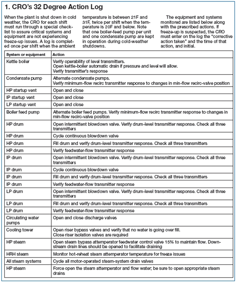
• CRO’s 32 Degree Action Log. This identifies equipment and systems that the CRO must check in cold weather to guard against freeze-up issues. Temperatures between 21F and 32F require the actions once per shift while temperatures 20 degrees and below require the actions twice per shift (Sidebar 1).
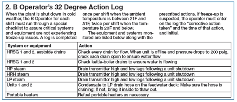
• B’s 32 Degree Action Log. Requires the outside operator (B Tech) to verify certain drains and transmitters are not frozen under the same temperature requirements as stated above. They also make sure that any portable heaters are working and have plenty of fuel (Sidebar 2).
• Operations personnel verify through rounds that all heat-trace panels come on and are working properly below 38F.
• A September PM in the CMMS system assures that all heat tracing is working. If not, a work order is written and the system repaired.
• Another September PM: Fill all necessary transmitter legs with glycol.
Duties of the DSOM as described in the “Plant Policies and Procedures Manual” covers a wide array of responsibilities, such as supervising the work of the operations department, developing and drafting lesson plans, conducting training, providing managers with technical expertise and knowledge, etc. The program also acts as a “tryout period” allowing managerial staff to critique the abilities, desire, and potential for development of each participating CRO.The core objective of the program is to maximize employee development by allowing upper- level operations staff to gain experience in the managerial aspects of power generation while also providing management with direct access to operator-level activities and knowledge for the purposes of planning and reliability.
It also allows the participants to experience day-to-day activities on a managerial level so they can determine if the “next step” is appropriate for them. Highly knowledgeable and proficient employees with the desire to advance will be well prepared to step into managerial roles with the least amount of transitional stress, thereby increasing the likelihood of success in their new roles.
There are several expected benefits to what is hoped will be a pilot program for the company. First, in light of the expected increase in natural-gas-fired power generation, the O&M provider for the facility will be well positioned to continue to offer the highest level of experience and support to its customers.
Secondly, by engaging in employee development and promoting from within the existing pool of talent, the plant operator will be creating a base of loyal employees who will be more likely to devote their entire careers to the company.
Given the challenges faced by the industry in the form of an aging and retiring work force it is crucial that companies within the industry create the means for retaining talented individuals. The financial benefit of retaining talent and limiting turnover is well worth the effort of the program.
Results. To date, the DSOM program has completed one full rotation of all five CROs. The consensus among the participants is that the program is creating positive results. All feel they have gained insight into managerial activities and knowledge that was not available to them prior to the program. Continued success is expected as the program advances.
Project participant:
Dwight Beatty, O&M manager
Jeff Hamrick, CRO
Extreme-weather preparedness increases availability
Best Practices Award
Challenge. Dogwood Energy Facility is a 650-MW combined-cycle plant located just outside of Kansas City. Its location makes it susceptible to a wide range of weather- related problems, exacerbated by having most of the plant located outdoors.
Since the plant is an independent power producer and operated by a staff of only 24, making sure the plant is ready to run at any time is very important. The biggest obstacle to availability is that the plant has to deal with the freezing temperatures, snow storms, and tornado season.
Freezing temperatures. The following is a list of action plans and preventive- maintenance techniques to prepare for winter weather:Solution. As a part of the site’s continuous improvement culture, personnel are encouraged to help identify issues along with determining the best workable solutions. As a result the plant has come up with several program elements that keep its availability high. The following are the problems the plant has had to face and the solutions that have been put into practice to mitigate them.
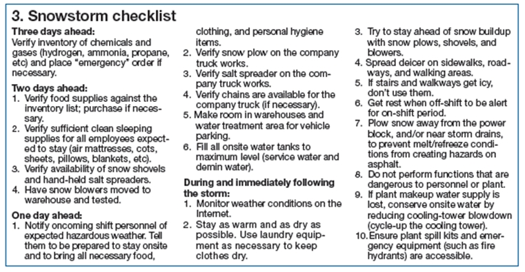
Snow storms. A comprehensive checklist was developed to help systematically prepare for and respond to snow storms where getting certain equipment and supplies to the plant might be impeded because of the weather event (Sidebar 3).
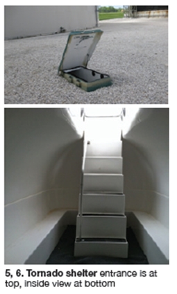
Tornados. Since the plant resides in an area known to have a high rate of tornadic activity, the facility decided to invest in storm shelters that would help protect staff and any contractors onsite (Figs 5, 6). Two storm shelters capable of accommodating 20 persons each were installed. One is located behind the main building and the other is by the contractor trailers. These shelters meet the following requirements:
• FEMA Publication 320
• ICC 500-2008, “ICC/NSSA Standard for Design and Construction of Storm Shelters.”
• ASTM E 1886-05, “Standard Test Method for Protective System Impacted by Missiles.”
• NPCTS, “National Performance Criteria for Tornado Shelters.”
Results. Because the plant is an IPP, any chances to run that are missed is a loss to the owner. The facility’s equivalent availability factor for winter months has increased from a low of 95% to a high of 99.9% over the course of the last three to four years due primarily as a result of the programs cited above.
Project participants:
The entire plant staff