


The global economic downturn will impose new challenges on plant operations. It’s difficult to believe that you will be asked to do more with a smaller budget, but you will. However, approaching these new challenges with a positive mindset can yield significant benefits. One might be that your junior staff is forced to learn more about power-generation processes, equipment, and systems, thereby increasing the level of expertise onsite.
An area of possible cost-cutting at some gas-turbine-based cogeneration and combined-cycle plants is in heat-recovery steam generator (HRSG) inspection. Developing on-staff capability to conduct base-level HRSG inspections saves both money and the need to schedule yet another service organization into an already complex outage matrix.
Most plants have considerable gas- and steam-turbine expertise but many do not have on-staff experts for HRSGs and generators. Developing HRSG know-how begins with understanding the types of degradation/damage that can occur and where to look for each.
To compile the checklist that follows, the editors attended the HRSG Academy conducted by HRST Inc, Eden Prairie, Minn. The engineering services firm focuses on inspection, training, O&M, and redesign projects for this special class of steam generators. It conducts two “academies” annually in North America and periodically in international locations. Each hosts up to 50 to 60 “students,” the maximum practical class size to assure constructive interaction among lecturers and attendees while allowing all an opportunity to have their questions answered.
The HRSG Academy may be the best program in the industry for teaching plant personnel the fundamentals of heat-recovery steam generators. A graduate who later becomes his or her plant’s resident “expert” on HRSGs is likely to attend the Academy a second time-to dig into specifics. Think of Shakespeare here: You can’t possibly understand and absorb everything in one pass, or even two.
The segment of the academy program dealing with HRSG inspection was “taught” by Lester Stanley, Scott Wambeke, and Amy Sieben, all licensed professional engineers with a wealth of experience in HRSG design, inspection, and trouble-shooting. Their course covered both online and offline inspection. The first encompassed data review tasks conducted in and around the control room and field tasks requiring a unit walk-down. Offline inspection was divided into gas-side, exterior, and drums. Also included was a primer on nondestructive examination (NDE) techniques and on sampling of deposits and pressure parts.
Online inspection
Stanley opened the online segment of the program by stating its goals:
- Identify poor operating practices.
- Identify areas requiring attention when plant operation permits an offline inspection and/or during the next maintenance outage.
Data review tasks
The best place to begin your inspection, the three instructors agreed, is in the control center where you have access to personnel familiar with the plant’s operational idiosyncrasies as well as to historical data. This investigative work generally is done while the unit is operating to be sure it does not impact outage duration. HRST uses a basic 10-point checklist for the data-review task, but items may be added and/or deleted depending on plant design and other considerations.
1. Feedwater control. Three of the many questions you should ask operations personnel are these:
- Do you see large fluctuations in feedwater flow during “steady-state” operation?
- Does feedwater flow start and stop frequently during startup?
- During overnight shutdowns, is there frequent “topping-off” of the drum to maintain level?
A “yes” answer to one or more of the questions means there’s risk of thermal-shock damage-especially in the coldest tube panel. These actions cause thermal-stress events to economizers and feedwater heaters within the HRSG. The number and duration of events influences how quickly tube leaks and cracking will occur.
2. Steam drums. First thing to investigate is the consistency among drum-level transmitters, level gages, and probe indicators.
If all are not in agreement, consider checking the calibration method and the pressure and temperature compensation settings for the level transmitter.
Don’t overlook asking if the “agreement” among level indicators differs at high and low steam loads and/or high and low drum levels. Stanley said that HRST often inspects high-pressure (HP) drums with water-level marks that are several inches too high, yet the operators say they are controlling to the OEM’s guidelines. This means there is disagreement between the indicated and actual drum levels.
Concern here is that if the operators experience a high-drum-level event, they may think they’re operating below the “high-high” level (HHL) but are actually above it and drum water may be carrying-over into the HP superheater.
Wambeke mentioned, “You now see that the value of a thorough annual inspection goes well beyond identifying wear and tear that requires repair. It enables the operations team to see what’s really going on in the HRSG and suggests fine-tuning of controls and procedures to avoid incidents that can damage equipment unnecessarily.”
Stanley continued, “Ask if the rates of pressure increase and/or decrease during startup and shutdown exceed OEM guidelines.” If “yes,” you should be concerned about the possibility of fatigue damage at manways and thick nozzles and carefully check those locations when the unit is out of service.
HRST engineers are seeing more and more HRSGs with crack indications on downcomer nozzle welds, supporting what many in the industry have been saying for years: HP-drum nozzles are high on the list of components most susceptible to cycling stresses.
Sieben added that spin cooling is hard on the HRSG too. “Most operations personnel don’t seem to approach shutdowns as carefully as they do startups,” she said, “and a fast cool-down can be just as damaging as a fast start.”
3. Desuperheaters get a significant amount of podium time in virtually every HRST presentation on boiler health. Poor design, leaking valves, ineffective spray nozzles, a lack of instrumentation, and other factors can wreak havoc at cogeneration and combined-cycle plants, putting personnel safety at risk and causing equipment damage that should never occur.
One of the first things to investigate is spray-valve behavior. Is spray-valve position near constant at steady load or does it fluctuate-sometimes closing entirely? If your spray valve is continually hunting-that is, opening and closing dozens of times each hour-the hot/cold cycles eventually will stress desuperheater nozzles to failure and possibly create other damage as well. Control-logic adjustments generally can rectify this condition.
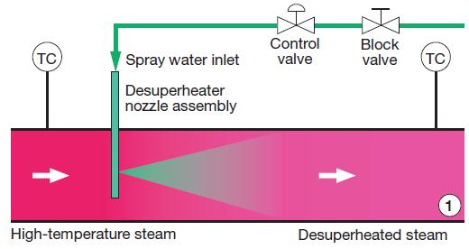
If your desuperheating stations are properly designed and equipped with thermocouples (TCs) upstream and downstream, verify that both are reporting about the same steam temperature when the control system indicates that the spray valve is closed (Fig 1). If this is not the case and the downstream TC is reading lower than the upstream one, water probably is leaking by the “closed” valve.
Give this immediate attention. Concern is that during startups and shutdowns, water can dribble into the steam piping, collect along the bottom of the pipe, migrate downstream to superheater and/or reheater upper headers, and then run down a few tubes. Cooling effect of the water causes those tubes to contract. Resulting stress can cause tube bowing and tube-to-header weld cracks.
Also check plant data to identify times when spraying to less than the saturation temperature of steam in the pipe plus 30 deg F. Do a thorough review: startup, steady-state full load with and without duct firing, steady-state low load (less than about 120 MW for an F-class gas turbine), and during transients. Desuperheating to near-saturation temperature creates the potential for damage like that described above for a leaking spray-water valve.
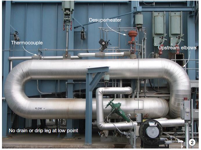
The thermocouple is so close to the desuperheater it gets quenched by water droplets, thereby providing erroneous data. Specifically, operators don’t know how close to saturation temperature that the plant is operating. An improved pipe location for the TC is needed.If your data review reflects the possibility of desuperheater problems and you are unfamiliar with the attemperation station, walk it down while the plant is operating to see if design/installation deficiencies exist. Fig 2 shows a poor desuperheater arrangement. When Stanley flashed this picture up on the screen, he noted the following:
- The desuperheater is too close to both the upstream and downstream pipe elbows. Problems created: Steam flow to the attemperator is not uniform and spray water is not fully evaporated before impinging on the downstream elbow. Latter causes fatigue damage to the elbow.
- There is no drain at the low point, allowing water to pool and to create “water events” during startup.
4. Stack temperature. Recall that high stack temperature is indicative of inefficient operation. Compare the actual readings at high and low loads and compare to known benchmarks. A large difference between the actual and known signals a problem. Check common causes-such as debris accumulation on finned-tube surfaces-and take corrective action.
5. Water temperature at economizer outlet. Compare the water temperature at the economizer outlet to the saturation temperature of water in the steam drum at the exact same time. If the two are within a couple of degrees, Wambeke said, then water exiting the economizer contains steam. Avoid this condition with startups that are as short as possible and maintain economizer feedwater flow. Venting appropriatedly during filling and startup also is important.
Keep in mind that air pockets block water flow and once a circuit is blocked it will steam up, making it even more difficult to “clear” during startup. If the temperature of the water at the economizer outlet makes several sudden jumps upward during startup from a lower-than-expected value, this generally means a vapor pockets are being cleared and normal operation is being restored. However, such clearing events, similar to water hammer, stress the economizer unnecessarily.
Stanley also suggested that you compare an operating point to a known benchmark. A large difference is cause for concern. Check for steaming, gas-side fouling, vapor locking from trapped air, gas bypass, etc, and take corrective action.
6. Water temperature at economizer inlet. Review data to identify any incidences of rapid temperature change (30 deg F/min, plus or minus) when the unit is in operation or offline. Such rapid change is viewed as a thermal shock to the economizer. Also verify that the inlet temperature doesn’t drop below 120F. Low temperature is the cause of dewpoint condensation and tube wastage.
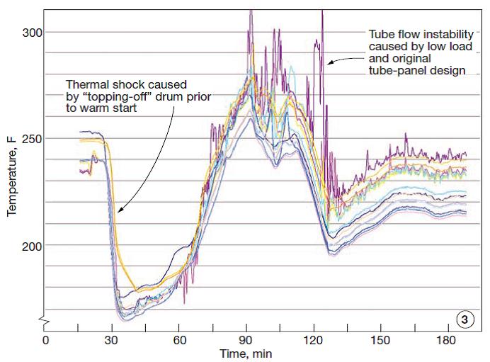
Don’t be surprised if the data you seek are not available. Sometimes permanent TCs are located in places that don’t indicate what actually is happening in the tube panel and test TCs must be installed. Fig 3 shows what an inspection team learned about temperatures during startup when test TCs were installed at strategic locations within an LP economizer.
7. Economizer recirculation pump. Verify during your inspection that the recirculation pump is operating early in startup and before new feedwater is added to the LP economizer. This allows the recirc flow to buffer the temperature difference between the hot tube panels and the relatively cold water being injected into the circuit.
When the pump starts, listen for audible signs of cavitation. HRST engineers have been in several plants where poor design of the recirc system has caused recurring cavitation and pump damage-in some cases so severe that the plants no longer use their recirc pumps. However, this is not a solution because the economizer can be damaged by thermal shock and/or dewpoint corrosion.
8. Superheater and reheater drains. Proper drain operation is critical for protecting superheaters and reheaters from large thermal shocks caused by the failure to remove condensate prior to startup. Stanley stressed that your inspection should, at a minimum, confirm the following:
- Low-point drains are open during startup to purge water/condensate prior to admitting steam to tube panels (harps). It’s relatively easy to check the timing of motor-operated drain valves; for manually operated valves, verify that proper procedures are in place and followed.
- Drains are open sufficiently early in the startup process to ensure that all condensate actually will be drained prior to steam admission. Operators at some plants where drains open to a funnel verify drains are clear of water by sound: A drain discharging steam makes more noise. A more scientific approach is to install TCs on the drain pipe and monitor for a reading above the saturation temperature.
- Drains are open during a trip, restart, and purge.
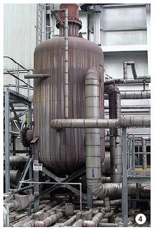
- Panels do indeed drain completely when drains are open. The elevated drain tank in Fig 4 requires sufficient pressure in the drain system to push condensate up into the vessel. Drain tanks located in a pit are better because they allow gravity draining.
Also check to see that HP, IP, and LP drains are not combined in a common collection pipe upstream of the blowdown tank. Reason: Flow through the HP drains could force water back into the IP or LP system if all the drains are open at the same time. Guidelines for proper drain system design can be found in the “HRSG Users Handbook,” published by the HRSG User’s Group (details at www.hrsgusers.org).
9. Selective catalytic reduction system. Compare historical ammonia consumption and outlet NOx readings. Rapid changes to NOx emissions or ammonia flow may identify catalyst plugging or poisoning or ammonia supply issues. Catalyst can be plugged by insulation released by way of transition-duct failure; ammonia injection nozzles can be plugged by contaminants in the reagent or by rust in lances; in oil-fired turbines, unburned fuel sprayed on catalyst during failed start attempts can ignite later and sinter the catalyst.
10. Gas-side backpressure. Does overall HRSG backpressure compare with OEM predictions? If not, what sections have more backpressure than predicted? If you can determine where backpressure is high, then the boiler inspection can investigate more carefully during the next outage. Gas-side cleaning of finned-tube sections is one solution. More proactive inlet-duct liner and insulation maintenance may be another if fouling by insulation fibers is to blame.
Online field tasks
Some key inspection tasks only can be done while the HRSG is operating-identification of casing hotspots, for example. Here are five things Wambeke suggested that you should be sure to accomplish during your online walk-down:
1. Check the supplementary firing system. Look through all view ports to determine flame health and duct-burner condition. Bullet points below provide some guidance for this activity based on HRST’s experience.
- A flame length in excess of 12 ft for an F-class HRSG is too long. Reason: Long flames, typically caused by low exhaust flow and/or poor distribution of exhaust flow across the burner, can “lick” tubes in the first panel and cause localized overheating.
- A bushy flame is desirable-that is, unless it is angled upward or downward, which indicates a problem with exhaust flow to that portion of the burner.
- A bright yellow flame is good; dull orange indicates too little exhaust flow.
- Monitor CEMS data as supplemental firing is initiated and shut off. Noticeable step changes in NOx and CO levels may indicate a burner problem.
- Check the integrity of burner elements and baffles. If breakage occurs, there is the possibility of damage to firing-duct walls and floors and to downstream tube bundles.
2. Watch for deflection of superheater and reheater floor pipe penetrations during startup and shutdown. Temperature differentials across superheater and reheater tube bundles can cause the panels to bow, exacerbating drain-line lateral movement. Drains that collide with the floor liner or casing often suffer stress-induced cracking.
Stainless-steel bellows have difficulty moving laterally, while fabric seals in high-temperature locations typically stiffen-up. The extra motion created by panel bowing often causes bellows to crack and tear. On fabric seals, bands pull lose and the fabric kinks. Latter creates small holes and leaks that propagate into fabric blowouts.
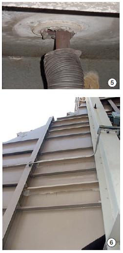
Fig 5 shows a superheater drain seal that has ripped loose from the floor casing because of excess lateral movement combined with the expected axial motion.
Stanley urged all attendees to also look for “stick and slip” of pipes during startup-a sign of hard interference with the floor. He said what happens is that drain lines don’t move much as the superheater warms up and then suddenly-bang-the pipe drops an inch or so. A little while later there’s another bang and another drop. Such hard contact/expansion interference obviously places unnecessary stresses on drain lines.
3. Stop, look, listen-for vibration. Listen carefully during your online walk-down. When standing alongside the transition duct connecting the GT outlet to the HRSG, do you hear any rattling or flapping sounds? They can emanate from loose and vibrating (a) internal liner sheets on walls, floor, or ceiling, (b) flow distribution plates, and/or (c) superheater baffles.
Recall that the perforated flow distribution plates even out flow across the transition piece just upstream of the duct burner; superheater baffles prevent gas bypass around the tube bundle.
Do you hear and/or see the casing pulsing or vibrating? Pay particular attention to the inlet duct to the HRSG, SCR cavity, and stack breeching. Vibration can fatigue internal liner support studs; if they fail, the liner and insulation may be lost.
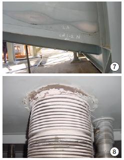
Sometimes a casing vibrates simply because it doesn’t have a sufficient number of stiffeners. The inlet-duct sidewall panel in Fig 6 has 10 horizontal stiffeners. But looking closely, note that the second, fourth, seventh, and ninth stiffeners (moving upward from the ground) were added after startup to address repeat liner failures attributed to casing vibration. The new stiffeners are larger and painted a different color than the originals.
Vibration of walkways and platforms may be more obvious than casing vibration. If noted, look closely to determine if the source of the vibration is the HRSG.
Stanley said to also check large-bore piping for steady motion. If piping entering or exiting the HRSG is constantly rocking, the source of the disturbance could be the tube panels vibrating in the “breeze” of the GT exhaust stream. Repetitive motion can cause fatigue damage. When the unit is offline, push hard on tube panels to see if they swing or sway. If so, install better tube-panel restraints and guides.
In some cases, sophisticated analysis is needed to determine the root cause of vibration. A noise signature often can help in this regard. Occasionally, vortex shedding in the tube bundles can create acoustic resonance problems. These may be noticed near the HRSG and/or in nearby buildings. Comparing calculated and measured shedding frequencies can give clues.
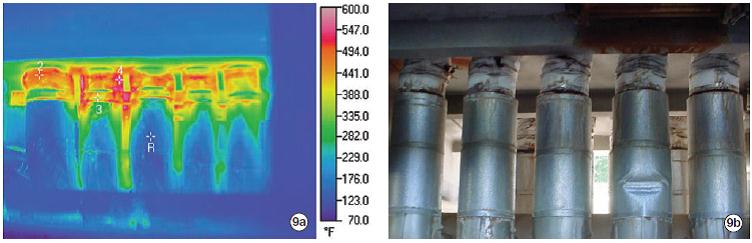
Stanley said that casing temperatures above 350F are especially problematic if several square feet of casing are affected. Such high temperatures combined with the affected area cause restrained expansion which, in turn, results in cracking of casing steel-sometimes severe. Most paint will discolor above 350F and cracking is a possibility, especially in areas where the casing is stiff-such as floors and roofs.4. Identify hotspots. Begin with a visual survey of the casing for burned or discolored paint-for example, the pink area in Fig 7 at the lower portion of the inlet-duct sidewall. Then use an infrared gun to measure metal temperature; next, map temperatures and prioritize corrective action.
Don’t forget to point the infrared gun at pipe penetrations, expansion joints, casing doors, field joints, and duct corners. The stainless-steel bellows seal under the HP superheater in Fig 8 reveals a hot spot where the seal attaches to the floor casing. Probable cause is a lack of insulation inside the bellows. High-temperature areas of the economizer drain-pipe penetration seals in Fig 9a pinpoint leakage through torn fabric. R is the reference temperature of 142F; Point 2 is at 519F, Point 3 at 390F, and Point 4 at 589F. Wear and tear on the seals is evident in Fig 9b.
5. Check pipe supports. First step is a visual survey to confirm that all supports are connected and not at maximum travel in the “hot” condition. Record locations of all supports for comparison purposes during later inspections.
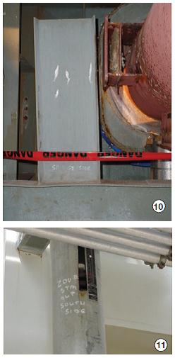
Also note damage to hangers, supports, insulation, and/or lagging that may indicate transient phenomena-such as water hammer. Fig 10 shows a guide for a reheater pipe that was bent by a water-hammer event. Spring hanger indicator in Fig 11 should be surveyed in both the “hot” and “cold” positions. The red (hot) and white (cold) diamonds indicate as-designed conditions.
Offline inspection
The HRST instructors divided the offline inspection module into four parts: gas side, exterior, drums, and so-called “extended scope” focusing on nondestructive examination (NDE). Stanley handled the first two; Sieben and Wambeke handled the remaining two.
Stanley began by stating four primary goals of offline inspection:
- Document equipment condition.
- Identify items requiring immediate maintenance.
- Note emerging problems, thereby allowing time for analysis.
- Begin planning and budgeting maintenance activities for future outages.
Gas side
Key to an effective gas-side inspection, the HRST instructors told the group, are the following:
- Dedicated, meticulous inspectors. They recommended a mixed team consisting mainly of in-house personnel and some outside experts with broad industry perspective. Also stressed was that any inspection worthwhile undertaking should be done properly; good inspections, Stanley continued, take days, not hours.
- A detailed record of observations and other facts. Take plenty of photos and measurements; describe observations in detail using a digital recorder and transcribing/editing your voice notes. Critical measurements might include material thickness in areas experiencing FAC (flow accelerated corrosion) attack, length of any cracks identified, distances across any cracks found, etc.
- Organize facts logically. Link every fact to a specific location in the HRSG. Editor’s note: Perhaps this goal can be facilitated through use of software customized for your specific boilers. To learn more, access www.combinedcyclejournal.com/archives.html, click 3Q/2007, click “Knowledge retention: New software tools help improve plant reliability, reduce maintenance cost” on issue cover.
Your ultimate goal should be to provide a comprehensive follow-up checklist with detailed notes so someone else can conduct next year’s inspection having the same knowledge you possess-that is, to pick up where you left off without missing a beat.
- Recommend a follow-up NDE program for areas where problems are suspected. This might include one or more of the following: borescope examination, ultrasonic (UT) surveys, dye-penetrant (PT) testing, magnetic-particle (MT) examination, hardness testing (particularly where P91/T91 materials are used), etc.
For inspection purposes, Stanley segments the HRSG into three areas:
- Access lanes-including inlet duct, firing duct, SCR, between tube bundles, and stack.
- Crawl spaces under and above tube headers.
- Exterior-including roof casing, floor casing, walls.
Your inspection should go beyond what HRST would do under its standard HRSG contract. Engage other experts to examine your steam valves, safety valves, silencers, instrumentation, piping to/from the HRSG, etc.
Inlet-duct checklist. Inspect the liner system for loose plates, spinning washers, exposed insulation, and failed studs. Fig 12 is typical of what you might find. Here studs failed and washers were liberated leaving liner plates with minimal support. Once a liner plate moves and a gap is created between it and adjacent plates, insulation can be sucked into the flow stream. This creates a hot spot in the transition duct skin and allows liberated insulation to blind a portion of the SCR catalyst.
Be aware that problems often are experienced with flow distribution plates. Also, check harps for corrosion, warped tubes, and vibration wear from tubes contacting-that is, banging into or rubbing against-each other when the unit is in service. Baffles and tube ties should be inspected for vibration damage, wear, expansion interferences, and weld cracks.
Figs 13, 14 show failed tube-fin tab welds that caused “rattling.” Some failed tabs rub directly on tubes. Although no gouges were identified in this case, if condition is left uncorrected, tube wear will continue (tube-tie components are harder than the tube material). Such wear often is worst at lower elevations, which is convenient because they are easier to access for inspection. Note that the inlet-duct superheater panel in Fig 15 is missing center baffles.
Firing-duct checklist has five focal points for your inspection:
- Liner system. Inspect the same way you did for the inlet duct.
- Duct burner. Look for sag in elements or baffles, nozzle plugging, and coke buildup; verify that burner “wing” condition is satisfactory.
- Tubes and fins. Inspect the same way you did for the inlet duct. But also check for evidence of flame impingement or local hot spots as well as for tubes bowed because of desuperheater issues.
- Baffles and supports. Look for loose or missing baffles, plus overheated tube ties and baffles.
- Firing-duct TCs. Be aware that most thermocouples are too short to read representative temperatures. Also, that TCs typically have no radiation shield and they are influenced by cool tubes and burner shine.
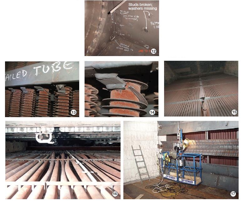
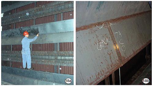
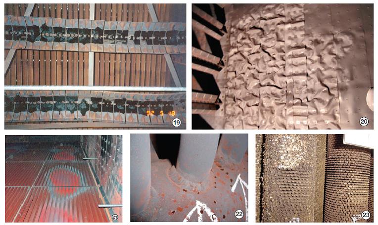
Burner coking sometimes is found when alternative fuels are burned. Fig 19 shows coking on a duct burner firing refinery gas. Olefins reportedly were the cause in this case. Coking can occur when burning natural gas if there is poor mixing of air and fuel at the burner.Figs 16-21 illustrate what to look for when inspecting the firing duct. Bowed reheater tubes in Fig 16 are downstream of the desuperheater, which probably allowed wet steam to enter the tubes. A Sky Climber or scaffolding is needed to perform a good duct-burner inspection (Fig 17) and repair any cracking identified (Fig 18).
An overheated liner protecting the sidewall of a firing duct is shown in Fig 20. Hot-spot indications on tubes downstream of duct burners are illustrated in Fig 21.
Tube-bundle access-lane checklist. This list begins, like the inlet- and firing-duct checklists above, with the liner system. Same principles apply. Next, tubes and fins should be inspected for corrosion, warping, and fouling. Warping of superheater and reheater tubes caused by poor control of the desuperheating process is relatively common (refer back to Fig 16). Warping is also indentified with LP and IP economizers that share common headers with HP economizers (for more detail, access www.combinedcyclejournal.com/archiveshtml, click 1Q/2008, click “Module, header replacement. . . .” on issue cover.
Look carefully for tube-to-header weld cracking (Fig 22). It can accompany tube bowing, but often is found as well on tubes that have not bowed. Tube bowing and cracking usually are caused by the same problem: Wet steam entering the tube field.
Tubes downstream of the SCR are susceptible to fouling by ammonia salts and by rust that flakes off carbon-steel fin and tube surfaces (Fig 23). The amount of sulfur in the fuel, and in the inlet air, impacts the rate of fouling; so does the amount of time the unit is offline, particularly in a humid environment.
Inspect bundles for wear caused by tube vibration. This will be found most often where tube-tie welds are broken and tubes are free to rattle around (refer back to Fig 14).
Fig 24 shows where baffles are located to avoid bypass of gas around heat-transfer surfaces. If metal deterioration is identified, make a note for maintenance follow-up. Also identify and correct areas where expansion/contraction adversely impact baffle function (Fig 25) and where baffles have slipped down tubes (often because fins have broken off) and created openings for gas bypass.
As you move back through the unit, Stanley said, look over the upstream face of the SCR catalyst for fouling-typically caused by rust and/or insulation fiber entrained in the hot gas (Fig 26). Gas bypass around the catalyst limits its effectiveness and could possibly put the plant out of compliance on NOx. Be sure to look for poorly installed baffling, open space around the perimeter of the catalyst bed, and gaps between baffling and catalyst frames.
Finally, look for openings between catalyst blocks and between the blocks and frames. Insulation between blocks has been known to compress over time, allowing catalyst bricks to settle. This can create gaps between blocks, especially in the top row of each module (Fig 27). Insulation then is free to blow downstream and plug LP heat-transfer surfaces.
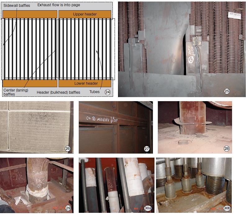
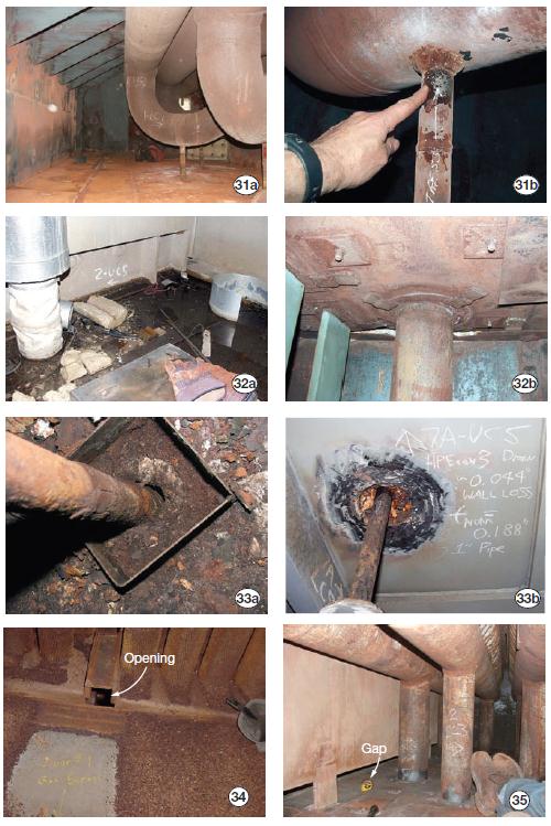
Inspectors examine floor debris for evidence of problems, the liner, liner fit-up around piping and hanger penetrations, baffles, bent piping, header corrosion, header/tube joint condition where visible, dripping water or corrosion/rust stains from tube leaks, etc. The photos in Figs 28 to 35 show some of the things you can expect to encounter.Crawl-space checklist. Inspecting the upper and lower crawl spaces in an F-class HRSG may not be much fun, but it certainly is where an inspector proves his or her value. Virtually everyone on the plant staff can hear casing vibration or see discolored paint at a hotspot, but only a well-trained and physically fit inspector can slither around a cramped, dirty crawl space and identify existing and possible future problems.
- A bent (and binding) liner donut around a pipe penetration in the floor liner is shown in Fig 28. A donut in such poor condition allows insulation to migrate upward, thereby creating a hotspot in the floor casing and limiting penetration seal life. It also allows debris to enter the seal underneath, accelerating damage to it and increasing corrosion risk.
- Fig 29 is a reheater pipe penetration with no liner donut, a condition that hastens degradation of insulation. A hotspot is created around the stainless steel bellows below because there is no thermal barrier between the 1050F reheat pipe and the bellows.
- Insulation slips down and out of stainless-steel bellows located above roof casing because no liner donut is present (Fig 30a). Roof-top photo reveals casing rust and blue tint to bellows indicative of operational hotspots (Fig 30b).
- Drain pipes under HP superheaters and reheaters are notorious for developing stress cracks-especially at the drain pipe-to-jumper weld (Fig 31a). Inspector’s finger points to what he believes is a crack (Fig 31b), later confirmed with dye-penetrant test.
- Debris accumulation on roof allows rainwater to pool (Fig 32a), leading to corrosion problems inside the HRSG. The result of long periods offline and water leakage is shown in (Fig 32b).
- Poor condition of drain line serving an LP economizer was found during an inspection of the lower crawl space below this HRSG (Fig 33a). HRST engineers recommended removing the stainless-steel bellows expansion joint around this drain, which had lost about 25% of its wall thickness in five years of service (Fig 33B).
- Gas bypass: Rust is swept away in region of high gas velocity downstream of the small square dark opening in Fig 34.
- Oversize gaps, which proper baffling should prevent, may avoid interference problems but they adversely impact performance (Fig 35).
Exterior inspection
By this point in the session, attendees were catching on to what they should be looking for when inspecting an HRSG. The checklist presented for this module had a familiar ring:
- Casing hotspots and cracking.
- Piping penetration seals.
- Access-door condition.
- Pipe hangers.
- Expansion joints at the round-to-square transition and between the HRSG and stack.
- HRSG foundations.
Of course, this isn’t all you should be inspecting on the exterior of your HRSG. Time limitations in the classroom and space limitations in the magazine militate against covering everything. When developing an inspection program customized to your plant, don’t forget such things as burner hardware, valves, safety valves and silencers, drum instrumentation, ammonia vaporizer, ammonia injection grid and associated piping and nozzles, etc.
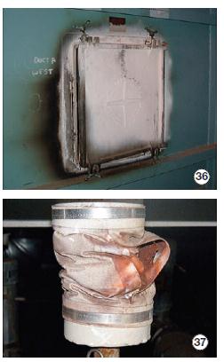
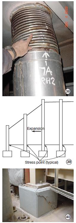
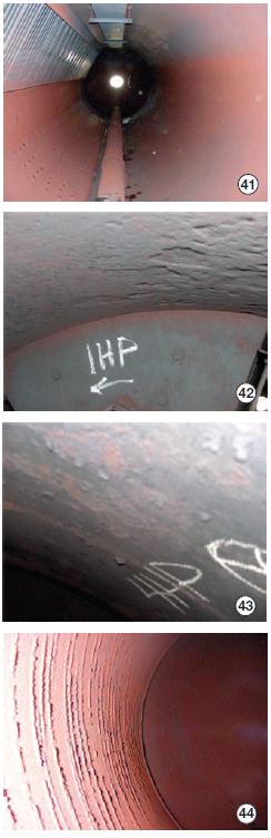
Fig 36 shows hotspot on access door and adjacent casing caused by leaking door seal and/or problems with the internal insulation pillow.Once again, photos taken during inspections conducted by HRST engineers give you a good sense of what’s important:
- Rust that accumulates in a fabric seal impedes its ability to flex and eventually the material splits (Fig 37). Liner donuts that are maintained in good condition help prevent rust from dropping into the seal.
- Cracked stainless-steel bellows in Fig 38 is a casualty of excessive drain movement as discussed earlier. Mechanical seals are an alternative to fabric seals and bellows.
- Large casing hotspots can cause walls and/or floors to expand more than anticipated. Inflexible support columns can create stress points, cracks, and hot gas leaks at locations shown in Fig 39. One example is foundation cracking in Fig 40, caused by restrained expansion of the inlet-duct support column. Such cracking can be caused by hotspots or by improper bolting of the column to the foundation base plate.
Drums
Amy Sieben took over for Lester Stanley at the podium. First thing she mentioned: Steam drums provide the only non-intrusive access to the water/steam side of an F-class HRSG. That’s an important point. All boiler water eventually passes through one or more steam drums in a triple-pressure unit, so a great deal can be learned from a proper inspection.
Sieben’s checklist included the following:
- Inspect the drum internal surface.
- Investigate any signs of distress on steam separation equipment and the belly pan which are caused by thermal stress (cracks) or flow-accelerated corrosion (FAC). If components are worn, measure metal thickness to quantify the extent of material loss.
- Verify mechanical integrity.
- Determine if the actual waterline is at the level designers intended.
- Scoop-up and carefully examine drum debris. Run tests to characterize the debris if necessary.
- Check the manway ring to see if machining is necessary to restore it to the desired flat condition.
A thorough examination of the drum internal surface demands that you get up close to the metal and look for pits, nicks, cracks, tubercles, corrosion, erosion, etc. Take notes and pictures of anything that looks out of the ordinary, Wambeke suggested from the back of the room.
Begin with a color assessment: Red is good in an oxidizing environment (Fig 41), bad in a reducing environment. Next, assess overall drum condition, tracking surface defects from manufacture-such as those created while rolling steel for the HP drum pictured in Fig 42. Scaling and lack of passivation during operation is illustrated in Fig 43.
Has smoothness/roughness of the drum surface changed during the inspection interval? For example, perhaps tubercles have formed (Fig 44). It is particularly important to identify any pitting attack and to inspect what the pits look like underneath. Keep in mind that pits may corrode under pits, resulting in pits larger than those at the surface.
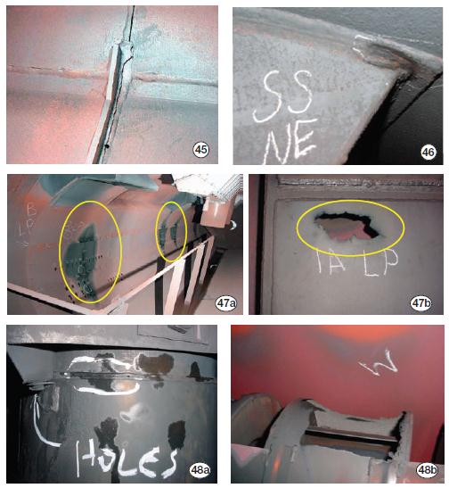
Signs of distress to look for on steam separators and the belly pan include the following:
- Cracks in the belly pan (or baffle plate), as shown in Fig 45.
- Cracks in the corners of the final separator (Fig 46).
- Thinning caused by FAC, as evidenced by the loss of material on the belly pan in Fig 47a and the hole in the LP belly pan in Fig 47b. Also, early FAC attack on the LP cyclone in Fig 48a and advanced attack (huge hole) on the Fig 48b cyclone.
Ultrasonic (UT) thickness measurements are useful for documenting the condition of drum internals, as well as of tubes and piping. Keep meticulous records to enable rate-of- wear calculations and timely maintenance planning. Standard UT measurements are all that’s needed to quantify material loss.
Thickness testing of internals compares original specifications of drum components to data collected during your inspection. More sophisticated UT-such as shear-wave and phased-array-are used to identify cracking.
The software described in last year’s Outage Handbook (see italicized editor’s note above) allows direct capture electronically of thickness measurements as the UT probe is moved across the surfaces of affected components. Data are stored in a manner that allows retrieval by clicking on a particular tube, header, etc, on drawings of your unit incorporated into the software package.
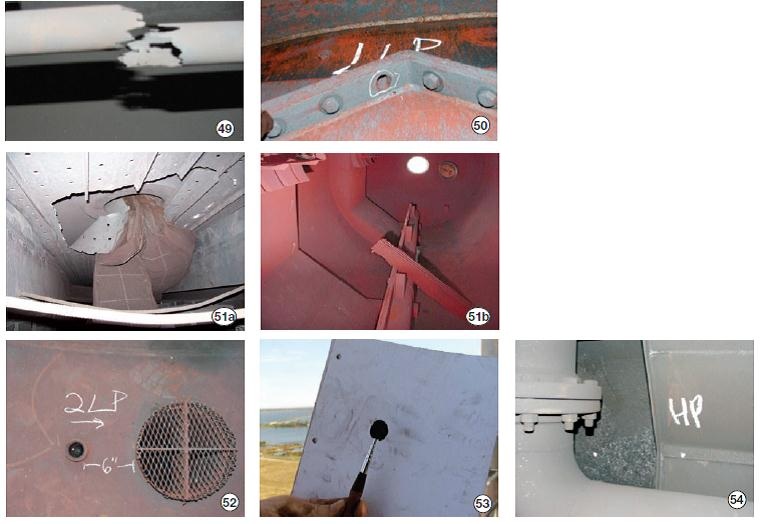
Water level. The primary cause of faulty level indication is instrumentation that is out of calibration. Sometimes, however, water level falsely appears lower than actual because the level transmitter is located too near a downcomer or pump intake. Their suction effect “pulls” on the level sensing lines (Fig 52). Plugging of sensing lines is another possible cause of false readings or sluggish response. Fig 53 shows a pencil-type magnet with debris pulled from a lower-level tap for an HP drum.Mechanical integrity. Look for the obvious: Broken “U” bolts, missing nuts and other hardware, plugged chemical-feed lines and separators, etc. Fig 49 shows a fractured chemical-feed line found in the HP drum of one boiler inspected by HRST engineers; Fig 50 reveals a bolt missing from a secondary separator; Fig 51a is of a mesh separator failure; Fig 51b shows a mesh-separator pad resting at the bottom of the steam drum.
Debris volume, if large, suggests possible rethinking of blowdown procedures and/or the need to check for iron transport caused by FAC. Fig 54 is a photo of iron debris found in a stagnant area of an HP drum at an end beyond the baffle. Also check for this material in the blowdown tank.
NDE basics
Sieben suggested, “Depending on the HRSG’s age, number and severity of cycles, and past issues, intrusive inspection techniques should be considered to more accurately assess boiler condition.” This might include one or more of the following:
- Ultrasonic testing (UT) of tubes and piping beyond spot checks; select optimum technology from among A-scan, phased-array, or shear-wave as specific tasks dictate.
- Dye-penetrant (PT) or magnetic particle (MT) testing of suspect areas.
- Removal and inspection of desuperheaters.
- Borescope examination.
- Sampling and analysis of pressure-part materials.
Ultrasonic testing. Recall how UT works: An ultrasound transducer connected to a diagnostic machine is passed over the object being inspected. The transducer typically is separated from the test object by a couplant. Reflection off the back wall or imperfection records the wall thickness or depth of the discontunity.
A-scan UT typically is selected for thickness testing, especially where FAC or external corrosion has been identified. It’s easy to use, fast, and accurate. Sieben offered an inspection plan that’s easy to customize for your HRSGs. She stressed that inspections should be prioritized based on risk.
- Examine LP evaporator circuits (plus IP circuits up to 400-psig saturated) and HP, IP, and LP economizer tubes that operate between 280F and 340F, the temperature range that exacerbates FAC attack. Wall thinning generally is experienced first after tube bends near the upper headers.
However, the risk of two-phase FAC is just slightly higher than single-phase FAC, so the lower-header inlets may be more convenient to check. To access the tube-bend area, remove header baffles as necessary.
- Check pipe elbows (jumpers) at the apex of the elbow; and straight runs downstream of control valves and orifice plates, especially where temperatures are more than 280F and less than 340F.
- Examine headers on HRSGs with “stick-through” welds on the headers directly across from the tube inlet. To review basics of tube-to-header joints, access www.combinedcyclejournal.com/archives.html, click 3Q/2004, click article title on cover.
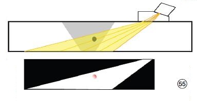
Phased-array UT makes use of multiple fixed-angle transducers in a single probe to quickly and accurately characterize flaws to provide the depth of indications, which show up as echo blips on the instrument’s screen (Fig 55). It has become the instrument of choice in GT inspections for its ability to identify even small flaws in complicated geometries-such as compressor airfoils, blade platforms, disks, etc.
No work stoppage or welder relocation is required to check work because there are no safety hazards with UT as there are with RT (radiation).Leading technology has its price. Phased-array instruments and probes are more complex and expensive than conventional UT and technicians require more experience and training to use it. However, compared to radiography (RT), the old standard in boiler work, phased-array UT offers several advantages, including:
- Inspections are conducted faster.
- Better suited for the detection of planar, crack-like indications-such as lack of fusion-which are conducive to premature failure.
- The exact depth of a defect is revealed, facilitating its removal and rework. Digital RT is making great strides to eliminate or minimize this list.
Shear-wave UT is about two to three times less expensive, but does not give depth of indication. Best applications for it are straight pipe, elbows, and circumferential welds.
PT and MT methods are used to identify cracks at the surface of the base tube material at or near a weld. They also are used for regular checking of tube/header joints at the economizer water inlet when more than 500 start/stop cycles have been accumulated; to verify the integrity of superheater and reheater tube/header joints where warped tubes have gotten worse over time; and to pinpoint suspect leaks in vent and drain lines.
PT is a low-cost and widely applied inspection method for locating surface-breaking defects in all non-porous materials (metals, plastics, and ceramics). For inspection of ferrous components, however, MT often is preferred because of its subsurface detection capability.
Dye-penetrant inspection is used to detect casting and forging defects, cracks, and leaks in new products, as well as cracks on in-service components not visible to the naked eye. It is simple to use: Penetrant is applied to the surface, excess penetrant is removed, and developer is applied to make the crack visible. Little training is required to develop proficiency in conducting PTs.
The red dye used most often offers a high visual contrast against a white developer background. The developer draws out the penetrant from the flaw over a wider area than the real flaw, enhancing its visibility.
Perhaps the biggest concern in conducting a dye-penetrant inspection is surface cleanliness, offered Wambeke. But keep in mind that some cleaning methods are detrimental to test sensitivity. Occasionally, acid etching is required to remove metal smearing and to reopen the defect.
Magnetic particle inspection processes make use of an externally applied magnetic field or dc current through the material. They are based on the principle that the magnetic susceptibility of a defect in a ferrous material is markedly poorer-that is, the magnetic resistance is greater-than that of the surrounding material.
The most common MT method relies on finely divided iron or magnetic iron oxide particles held in suspension in a suitable liquid (often kerosene). This fluid is referred to as the “carrier.” The particles often are colored and usually coated with fluorescent dyes that are made visible with a hand-held ultraviolet (UV) light.
The suspension is sprayed or painted over the magnetized specimen to localize areas where the magnetic field has protruded from the surface. The magnetic particles are attracted by the surface field in the area of the defect and hold on to the edges of the defect and define it by a build-up of particles.
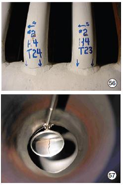
MT is used to inspect machined parts before they are placed in service and also to inspect parts in service for fatigue cracking (Fig 56). The testing method is easy to apply and takes less time than UT and PT, but it does not work well with complex geometries.
Attemperators in cycling service should be inspected annually. Look for cracking or distress on the desuperheater assembly; check nozzles for plugging; confirm liner integrity (see liner crack in Fig 57), and the absence of pitting/wear at the downstream elbow. If data suggest over-spray, inspect piping for cracks.
Borescope inspections commonly associated with GTs, steam turbines, and generators also find application in some sections of HRSGs. The most likely areas of use include the following:
- Economizer, cold end, when pitting or cracking of the tube internal surface is of concern because of cyclic stresses and/or water-quality issues.
- Economizer, hot end, if damage or deposits are suspected from water-quality excursions in conjunction with excessive steaming.
- HP evaporator, hot end, if water-chemistry excursions make internal deposits a risk or iron levels are above 1 ppm.
- LP evaporator tube rows most susceptible to FAC damage based on a circulation analysis or failure history.
- First tube bundle of the superheater downstream of the steam drum, if deposits from carryover are suspected because of a steam-separator failure.
Tube samples are taken to characterize both hard scales that form in LP boilers and magnetite and copper deposits in HP boilers. Such deposits reduce heat transfer and efficiency and make the HRSG more susceptible to overheating and tube failures.
Tubes are sampled only when available NDE methods are not able to meet expectations. Tube sampling is difficult, expensive, and has obvious inherent risks.
Laboratory analysis will suggest corrections to water chemistry and operating procedures and the most efficient method for removing deposits. Base metal analysis will advise on the condition of boiler tubes and whether expectations of service life must be revised downward. ccj