


Cogen plant in the oil patch gets a controls makeover
Replacing and upgrading controls systems serving gas-turbine (GT) cogeneration facilities installed one, two, and three decades ago continues unabated. CCJ editors recently visited one such plant in the California oil patch and discussed controls-related experience with the plant manager (PM).
Evidence of this manager’s I&C chops were additionally revealed in a 1991 ASME paper he co-authored: “Updating Cogeneration Control Systems for Improved Reliability and Operability.” In other words, he’s been at this for more than two decades.
Names are not revealed to avoid the protracted hassle today of gaining corporate approvals. It is, nevertheless, a tribute to the men and women in the trenches that they wish to disseminate best practices to the user community even if they have to do it anonymously.
Plant control goes where the operator goes. Once upon a time, a control-room operator sat in a control room, and roving plant operators kept their eyes on the equipment and handled local control functions. Perhaps the most interesting aspect of the controls at this site is that the operator takes them along. Not just monitoring capability, mind you, but full control of the plant.
As long as he or she is within range of the plant network, the operator can perform all control functions from a ruggedized, portable iPad. The only practical difference is the size screen and keyboard the operator works from.
What’s more, at this site, it actually means two separate powerplants. The owner/operator entity has three cogen plants in the region, two within a few miles of each other. Of these, one is a 38- MW facility with a GE Frame 6B engine and a once-through Vogt heat-recovery steam generator; the other is an 18-MW plant powered by two Solar Mars® turbines with Struthers Wells (today TEi-Struthers Wells Div of Babcock Power Inc) once-through HRSGs. All of the I&C for the smaller plant is connected to the larger plant control room through telemetry.
Common platform key. The third facility, a 42-MW plant featuring two LM2500 aero GTs and Struthers HRSGs, was the first to undergo a controls makeover. Commercialized in 1990, the facility’s original Mark IV gas turbine controls were replaced in 2011 by Wood Group GTS (now EthosEnergy Group) with Allen Bradley and Rockwell equipment from Rockwell Automation Inc.
Prior to that, in 2004, the Westinghouse WDPF serving the balance-of-plant (BOP) equipment was replaced with Siemens APACS, a programmable logic controller (PLC)-based DCS, by Craig Corzine, now the president of CSE Engineering Inc, which also supplied its own HMI (human/machine interface) called IBECS™.
When the 38-MW plant’s controls were up for retrofit, the idea was to have a common controls platform for the three plants. Corzine was called in to engineer a complete system from (1) the Siemens APACS and the CSE IBECS (with software from Canada’s Trihedral Engineering Ltd) which replaced the original Bailey Network 90 (Net 90) BOP controls (considered unsupportable) in 2005 and (2) Rockwell Automation controls which replaced the Mark IV controls in 2011.
Because the Siemens APACS is now considered obsolete, the owner/operator plans to replace it with Rockwell Automation’s ControlLogix® PLC-based system in 2017. As the facility was commissioned in 1987, this means three major control-system replacements in 30 years, a testament to how quickly digital technology progresses.
Common complaints. The original Net 90 became too costly to manage. I&C issues “were extremely difficult” to deal with. “It took plant personnel 10 years to achieve competency on fixing control system problems,” noted the plant manager, “reading the vendor manuals could never get you there.”
“For example,” he continued, “say we wanted to add a ‘point’ to the control system, such as monitoring a pressure transmitter. The Net 90 parts and hardware would cost us around $5K, require a complete plant shutdown, and involve complicated hardware changes—like dip shunts and hardwired dip switches, which then had to be properly powered. The consequence was that we avoided control-system changes like the plague.
“Today, we add a few wires, and make some software changes. All of the communication protocols are embedded in the IBECS system and the structure is relatively simple. It’s the equivalent of going from DOS to Windows for communications. It’s straightforward to add points and make modifications which improve performance and operations.”
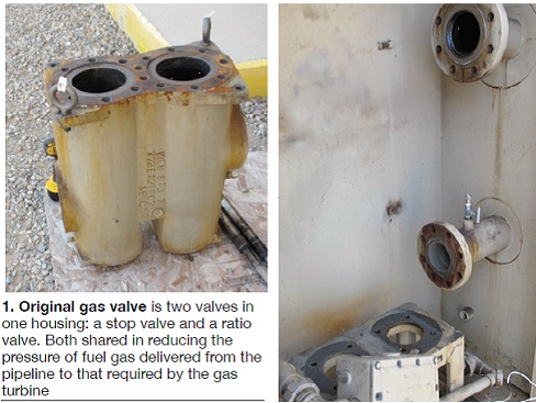 A new fuel-gas valve is an example cited. The one supplied with the 6B machine was a single valve that had to function as both a ratio valve and a stop valve. Both valves (in a common housing) shared in reducing gas pressure—the coarse pressure drop taken in the stop valve.
In 2013, the dual-function valve was replaced with a Young & Franklin electronic control valve and a separate stop valve outside of the GT enclosure. The original valve was instrumentation-limited. It required three computers to do two out of three voting on pressure. There was one pressure sensor but three transmitters.
Now, under the new control system, with 30 minutes of programming, there are three process points in the controls rather than one process point requiring three readings. This is what smart-valve technology is all about.
Rather than shutting down during discrete process upsets, the new controls allow the plant to ride out upsets. A fault on the main utility tie line used to open the breaker, flame out the turbine, and trip the unit, shedding 38 MW in one cycle. All of this placed significant duress on the engine.
Now the breaker can open, but the plant idles, and is easily reconnected to the grid. This capability has been tested twice, once because of a lightning strike. The facility also was able to continue operating during an incident in which the indicated fuel-line pressure temporarily increased from 300 to 600 psig.
In general, the new controls allow plant personnel to be proactive, rather than reactive. Causal relationships among critical plant parameters are illuminated, simplifying troubleshooting towards root causes. A 97.61% uptime factor in 2014 (through mid-December) confirms the improved performance of the facility.
That’s an impressive factor for a base-load facility that absolutely must run to maintain oil extraction.
Not only do cogen facilities of this type supply steam for lifting heavy oil out of the ground, they are repositories for the recycled condensate. In earlier times, the separated “nasty” water was simply re-injected into the oil wells. Today, that practice is verboten. The cogen plant must take filtered, softened water as feedwater to the HRSG. At 12,000 total dissolved solids (TDS) and 200 ppm silica, “our feedwater is a slurry,” noted the PM, wryly.
That makes for quite a maintenance effort around the HRSG. Even with a robust water-treatment regimen, scale has to be removed manually from the boiler tubes twice a year, according to the plant manager. Still, there is significant tube-wall thinning.
In effect, the electricity, 40% of which is used internally and 60% sold to PG&E, is a byproduct which helps offset the cost of pipeline natural gas to fuel the plant.
Electric fuel control valve streamlines plant operations
Like some other vintage Frame 6B-powered cogen plants, this facility in the California oil patch recently visited by CCJ editors, was plagued with fuel-gas valve problems, usually requiring at least a man-shift’s worth of work each outage to disassemble, clean seats/plugs, and reassemble. Sometimes an outage would have to be taken if leakage was indicated by the P2 pressure between scheduled outages.
The original valve actually was two valves within one housing, according to the plant manager (PM)—a ratio valve and a stop valve. Both valves share the job of reducing gas pressure from the supply line to that required by the turbine. The ratio valve takes the first pressure drop, but in that process, the fuel gas drops below its dew point, allowing sulfur-bearing liquid mercaptans to drop out in the second valve passage.
Over many operating hours, this leads to deposition which impairs operation and has to be removed at every planned (and sometimes unplanned) outage. The deposits get in the way of passing startup permissives, especially what’s known as the P2 test, which ensures that the ratio valve will not pass too much fuel into the turbine while it’s closed and create an explosion hazard upon ignition.
This occurs because the deposition leads to improper valve seating and potentially allows leakage. P2 is a leak-detection permissive in the control logic. Before light-off, the startup controls monitor fuel supply-manifold pressures.
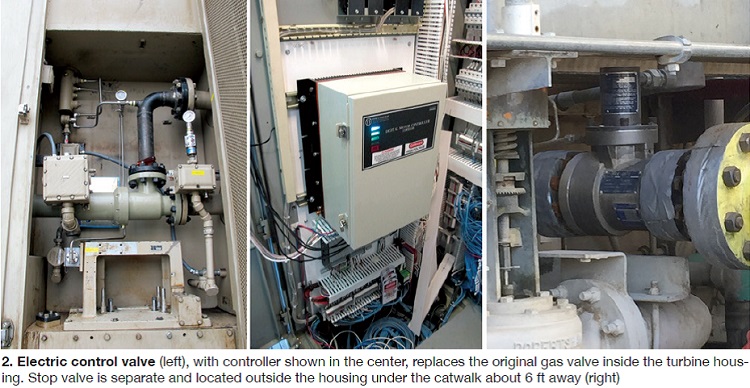
One solution offered by the marketplace is to reheat the fuel gas to above the dew point (120-130F) in between the valves, but this is considered far from ideal. The better solution proved to be replacing the original valve with a “smart” electric control valve (Fig 1) in the same location as the original and a separate solenoid-operated stop/isolation valve about 6 ft upstream—just outside and below the turbine enclosure (Fig 2). The control valve acts as a ratio valve and a control valve. The modifications were made in spring 2013.
Since then, reports the PM, the facility has avoided at least half a dozen trips. The deposition problem hasn’t been completely solved—borescope inspection shows that it still is occurring in the control valve—but, critically, not in the isolation valve. Additionally, the new control valve self-calibrates and is able to reset to a new starting position, usually few millimeters at most, based on any deposition. Thus, if valve stroke is off by one tenth of one percent, notes the PM, that position is used as a new “zero point.”
Finally, new startup curves are used at the plant based on the far superior sensitivity and flexibility of the new valve. The logic can recognize a 1% valve opening, far better than the 30% crude opening sensitivity of the original, and provide accurate, repeatable readings to the control system at small openings.
According to Young & Franklin, the valve supplier, the position transmitter has greater than 300:1 position turndown. The stop/ratio function can now be handled in the software. Previously, the plant would have to call a GE field service engineer out to make the modifications, create new control cards, and capture new instructions in the read only memory (ROM). CCJ