The first gas-turbine user group known to the editors got its start in the US in the mid-1970s. It provided valuable experience on the operation and maintenance of these relatively new prime movers, which were ordered by electric utilities in large numbers following the Northeast Blackout of 1965. Back then the dominant engines for power production were Pratt & Whitney’s FT4 and General Electric’s Frame 5.
With world leaders in the development of industrial GTs—GE and Westinghouse Electric Corp—headquartered here, where natural-gas transmission lines moved fuel over long distances relatively inexpensively and additional capacity always was needed, larger and more efficient engines debuted regularly, promoting a need for user groups to facilitate technical communication among the owner/operators. Meetings of these organizations attracted 60-Hz users from around the world.
But what about 50-Hz users? Until recently, there was no efficient way for CCJ to follow the frame-specific experience of these owner/operators, most meetings being small and geographically dispersed. However, over the last several years, the organization known as GTUsers.com has built a loyal following among European, Asian, and Middle Eastern owner/operators who regularly participate in its online and face-to-face conferences. CCJ and GTUsers.com have agreed to work collaboratively to help users share experiences globally.
Here are some facts about the V fleet to keep in mind as you read through this report:
- There are about 1000 V engines operating worldwide. This total includes both E- and F-class models operating at 50 and 60 Hz, providing plenty of experiences to share across national borders.
- Two OEMs manufacture V engines, Siemens and Ansaldo Energia. The engine designations for Siemens machines are SGT5-4000F (V94.3A, 50 Hz), SGT5-2000E (V94.2, 50 Hz), SGT6-4000F (V84.3A, 60 Hz), and SGT6-2000E (V84.2, 60 Hz). For Ansaldo engines, the designations are AE94.3A and AE94.2—50 Hz only. Roughly 80% of all V machines in service were made by Siemens, the balance by Ansaldo under a Siemens license.
- In round numbers, there are about five-dozen V84.2s operating in the US, three-dozen V84.3As. CCJ has covered the 60-Hz fleet since the mid-2000s. Siemens has hosted annual face-to-face meetings over the last decade and invited the editors to participate. The 2020 conference will run from September 14 to 17 at the Hilton Niagara Falls/Fallsview Hotel & Suites in Niagara Falls, Ont, Canada.
- com has hosted web meetings for V users since 2009, face-to-face meetings since 2014. The 2020 conference of the V94.3A users takes place in Prague, Czechia, October 12-15; the V94.2 meeting, Prague, Czechia, November 9-12.
What follows are summary notes from the 2019 V user conferences in the US and Europe, plant best practices, and technology updates from Siemens and several third-party service providers—including ARNOLD Group, Sulzer, and APG (previously known as Allied Power Group).
GTUsers.com
GTUsers.com, a web portal designed and maintained by Gasre Oy (www.gasre.com) to facilitate communication among owner/operators of gas turbines, transitioned from a “hobby” to a professional service in 2014. Coincidentally, the independent Finnish firm, launched in that year the development of its TMMonitor™ product for gas-turbine maintenance management and parts tracking. This software is represented in the US by Lodestar™ and Turbine Technology Services Corp.
The activities of GTUsers.com are coordinated by Yrjo Komokallio, a turbine specialist, who is CEO of Gasre. The web portal is segmented by engine type (currently 11 machines are represented), and access to the discussions, databases, etc, associated with each is restricted to the members of that group. You can be a member of a group only if you own and operate such a unit. The individual groups are controlled by their own end-user steering committees. In sum, more than 5000 users, representing over 1500 gas turbines, participate in GTUsers.com.
Pertinent to this report, GTUsers.com has hosted web meetings for owner/operators of V94.3A (SGT5-4000F, AE94.3A) engines since 2009 and for V94.2 (SGT5-2000E, AE94.2) machines since 2012. Annual conferences were added in 2014 and 2015, respectively. Last year (2019), the 94.3A group met in Istanbul in October, the 94.2 users in Berlin in November.
Sponsors of GTUsers.com activities familiar to CCJ readers include ARNOLD Group, Sulzer, APG, MD&A, Freudenberg, Liburdi, Dekomte, Trinity Turbine Technology, and Gas Turbine Controls.
V94.3A, highlights from Istanbul
There were eight V94.3A user presentations at last year’s meeting, half based on experience in Europe, half in Asia. The European speakers focused on the following: gas-turbine O&M history covering nearly 10 years, generator major, expansion-joint failure analysis and repair/replacement, and combustion tuning to allow an increase in fuel temperature. Presenters from Dubai Electricity & Water Authority discussed GT inspection findings, what is believed to be the world’s fastest major for this frame (11 days), and the underlying cause of fuel-oil flex-hose damage.
Here are thumbnail sketches of the assets upon which the presentations were based:
- Two single-shaft combined cycles with a total full-load output of 870 MW, designed for a nominal 300 starts annually, hot starts (less than 8-hr shutdown) in 15 minutes, warm starts in 50 minutes.
- Two single-shaft combined cycles built in the mid-2000s with a total full-load output of 850 MW.
- Early 2000s repowered oil-fired steam station (2 × 125 MW) burning gas with heavy-oil backup. Current configuration is two 363-MW 1 × 1 × 1 combined cycles.
- Standard 2 × 1 combined cycle rated 850 MW.
- Plant built in stages with 400-MW single-shaft combined cycles installed nearly a decade apart.
- A 590-MW 2 × 0 addition to power and desalination plant.
- Two 375-MW 2 × 1 combined cycles with flash distillers.
Perhaps there’s no better way to learn about plant operations than to listen to a user colleague give an objective review of his plant’s history and be able to ask questions. This speaker’s review covered eight years from commercial start to an extended HGP more than 34,000 EOH and nearly 400 starts later.
He talked about the plant’s experience with hexavalent chrome—sampling and measurement, and dealing with contaminated insulation mattresses. Conclusion: Further investigation is required to assure a safe working environment on the steam turbine.
Another safety topic discussed was working at height, including the use of davits to tie off worker harnesses when climbing on the turbine.
Moving to the compressor, the speaker discussed IGV actuator ring axial wear and repair, plus replacement of rollers, bushings, and pins. A diaphragm exchange made necessary because of wear at vane hooks was another talking point. Exchange of the compressor bearing shell because of damage, the need for new shaft coupling bolts, repair of the coating on the leading edges of airfoils, and other compressor topics kept attendees in their seats.
Mention of a trip caused by the unexpected closing of IGVs during baseload operation was a surprise highlight of the presentation. Analysis revealed the cause was servomotor internal leakage, considered an isolated incident.
In the combustion chamber, minor repairs were required. In the turbine, all vanes were disassembled and reassembled; a few were replaced. Plus, blades in Rows 1, 2, and 3 were renewed.
Recommissioning revealed engine work during the outage enabled a power boost of more than 2%; heat rate also was better.
The original metal-bellows expansion joint installed between the gas turbine and exhaust duct had 125,000 EOH and more than 1200 starts at the time of failure. Material was described as heat-resistant austenitic stainless steel. The expansion joint was designed for 12,000 cold starts, 620C operating temperature, ±50 mm elongation, and ±1 mm movement in the vertical direction.
Plant personnel knew they had a problem because both the temperature and the concentration of carbon monoxide inside the package had increased significantly. Plant operations were modified to avoid unit trips. Inspection revealed the joint had failed in two locations—at the 12 and 6 o’clock positions—and insulation was damaged. Temporary metal shields mitigated damage to affected components.
Temporary repairs were made about six months after the failure was identified, but the protective pillows and belting holding the pillows became ineffective over time and the replacement of the expansion joint became necessary. The new joint was installed during a steam-turbine outage.
There were difficulties with the installation, which should not be surprising. Examples: misalignment between the exhaust section and the gas turbine as well as cracking and deformation of the transition cone. Leak testing was the final step in the replacement project.
A finding during the root-cause analysis (RCA) investigation was that sliding feet on the exhaust cone were not performing as intended and hang-ups impeded expansion of the joint during turbine starts, causing stresses that contributed to cracking. At user meeting after user meeting the editors hear of problems with sliding feet on heat-recovery steam generators, rotor air coolers, shell-and-tube heat exchangers, etc. They should be inspected and lubricated annually.
The failure of flexible hoses for fuel oil can be avoided in many cases. The speaker describing her experience said that before the unit’s minor inspection, the operator received a fire-detector alarm, and personnel found the flex hose between one burner and the manifold ring completely torn apart. It was replaced. Flex-hose damage also was found on at least one other machine.
Like the condition of sliding feet in the previous experience, the condition of flexible hoses must be monitored. Subject matter expert Brian Hulse, a frequent contributor to CCJ, acknowledges that hoses are expensive and that users always try to extract maximum value from them before they’re replaced. Replace decisions are not easy because the hoses used on most gas turbines are manufactured with no published shelf-life or working-life limitation.
Hulse says plant O&M personnel should be aware that the following conditions impact hose life and to be on the lookout for them during inspections: chaffing, kinking, prolonged exposure to UV, mechanical abrasion, lying in fluids (water, fuel, oil, etc).
A simple database can help you avoid surprises. Include any recommendations on the care of hoses offered by the gas-turbine manufacturer in the O&M instructions for your machine, note the type of service for each hose cataloged, enter findings of routine inspections, inspection interval, inspection procedure, etc.
Also, bear in mind that some hoses are equipped with an exterior protective sleeve—usually called a “Firebraid” in the US after the trademarked product. This sleeve is designed to protect hoses from the hazards of high heat and occasional flame. If the Firebraid is torn, chaffed, or oil-soaked, the hose should be removed from service—especially if it too shows signs of distress.
A generator major was scheduled early based on the OEM’s recommendation to replace all hydrogen seals after about 64k EOH and 1700 starts. Wedge tightness was an initial concern when the unit was removed from service, but the inspection team ruled it “acceptable” based on results of a test method provided by Siemens USA.
Several small cracks were found on the generator’s PPS (hydrogen Performance Plus Seal™) segments. The bumper ring also was damaged. No obvious root cause was identified. The speaker advised that segments can be replaced onsite, but bumper-ring replacement requires a factory visit. Important: Damaged segments cannot be replaced individually; the entire ring must be replaced. Attendees also were made aware of the OEM’s development of a special tool for installing new PPS segments.
Several wrinkles were found in stator top bars. “Advanced” wrinkles could be seen by the naked eye; several other bars sounded hollow on one side when tapped in the same area. Insulation was cracked in areas revealing advanced wrinkles and it was repaired. Engineers determined that wrinkles and delamination were caused by thermal expansion/contraction of the bars during starts and shutdowns, which had increased in recent years. The repairs contributed to a significant reduction in partial discharge, which had been increasing over time.
Generator bushings were changed to ones with cast rather than welded supports to mitigate damage caused by vibration. However, the new design also showed signs of vibration damage on all three phases, as indicated by green dust. Engineers could not determine the cause of vibration.The three bushings had capacitance deviations, likely caused by bad connections between clamp and the inner electrical-field control layer. One bushing was replaced. The other two were relocated to new positions at “star” points, where there is no voltage stress.
An upgraded bearing (MKD11) was installed on the gas-turbine side of the generator because of tilting and problems during turning-gear start. The new bearing has improved lift-oil grooves and coated bearing saddles, but its normal temperature runs about 6 deg C higher. Monitoring of the new bearing is ongoing.
Combustion tuning was discussed by an engineer associated with a practical research project for a large generation company. The goal of the program was to minimize cost of power production while maximizing efficiency and output. Results enable the company to tune its engines at less cost than would be charged by the OEM.
The sticking point described was that while the gas turbine met performance guarantees, it was not possible to operate at the maximum fuel temperature (200C) at low ambient temperatures. The power generator wanted 200C fuel at all times to increase efficiency.
A solution was found whereby fuel temperature was raised and efficiency increased. The annual saving in fuel and carbon costs amounted to more than $US100,000. Plus, NOx emissions were reduced. Work on the project continues with the goal of fine-tuning combustion and saving still more fuel.
Outage time reduction is the goal of virtually all power producers when they are “in the money.” Speaker described how his company was able to reduce the time for major inspections on two gas turbines from 51 days in 2013 to 11 days in 2018 and 2019. Likely you find this hard to believe. Learn what’s truly possible by attending user-group meetings for your engine.
For this case history, be aware that plant personnel were motivated to set a world record for the major inspection of a SGT5-4000F. And they were empowered to do so. There was plenty of relevant in-company experience to draw upon: It owned and operated two-dozen V94.3As.
The first engine to complete its 11-day major (2018) required more than 12,000 man-hours of effort from a field staff of 115 working 11-hr shifts; the second engine’s 11-day major in 2019 took just north of 9400 hours with 95 field staff working 10-hr shifts.
Critical to the achievement were the following:
- Detailed planning and prioritization of work permits to minimize the time needed to isolate various systems.
- Created a fast-track entry process for staff and logistics at the security gate.
- Maximized onsite logistics—such as meals, laundry, transportation, etc—to minimize lost time.
- Conducted a kickoff meeting of all field staff prior to the outage to build a sense of ownership in the project.
- Shifted critical risky activities to outside the overhaul period. The thinking: The shorter the outage the lower the technical risk and the fewer the number of human errors.
Project planning was especially critical to success, the speaker said. Here were some of the key steps taken:
- Activities thoroughly planned in advance with resources mapped to overcome foreseen challenges.
- Staff qualifications were scrutinized and the best team selected.
- Optimized the work-shift model to permit round-the-clock activity.
- Organized and managed spare parts and tools to minimize time constraints.
- Conducted daily project review meetings to identify and eliminate schedule sticking points and to measure progress.
The speaker closed by identifying some considerations to shave days from the outage schedule, including these:
- Consider a rotor swap rather than a shop visit.
- Provide onsite capability for coating compressor blades.
- Review lessons learned and implement optimized findings into your plans.
- Swap out burners, valves, etc.
- Focus on enhanced project management techniques.
Inspection findings were reviewed by an engineer from a major generator. A summary follows:
- Minor inspection revealed TBC loss and some oxidation of the protective layer on the pressure side of two first-stage turbine blades, which were replaced.
- Linear crack indication on the platform of one second-stage blade, also replaced.
- Bearing balls found missing on one side of the turning-gear pinion. It was replaced.
- Lift-oil pump failure was characterized by black-colored oil, metallic chips in the filter, and coupling damage. After failed parts were replaced, oil was run through the filter until clean.
Extended HGP inspections on the gas turbines for one 2 × 1 combined-cycle block (nearly 68k EOH/314 starts) at a two-block plant revealed the following:
- Compressor bearing reverse thrust pads were found scored to a depth of 0.4 mm; coking was in evidence.
- All vanes were removed for NDE, two were replaced because of excessive caulking clearances, IGVs and first- and second-stage vanes were recoated, compressor blades in Rows 1-4 were recoated on the leading edges of the airfoils, some new tiles were required.
During recommissioning, new KV curve settings were required for gas control valves, newly implemented logic called for in product bulletins presented problems, compressor bearing temperature came in higher than expected, the baseload power output was lower than expected, a unit trip was experienced during a switch-over from diffusion oil mode to fuel gas.
The second combined cycle at the plant went through its extended HGP inspection the following year with some of the same findings identified with the first block—such as replacement of a few blades and vanes in the compressor, coating fix on compressor blades. Recommissioning of Block 2 also was similar to that of Block 1.
V94.2, highlights from Berlin
There were six V94.2 user presentations at the 2019 meeting, half based on experience in Europe, half in the Middle East. Speakers focused on the following: results of an extended HGP, follow-up on repairs to a compressor’s axial bearing after two years of operation, outage findings, damage to turbine blades attributed to domestic object damage, damage found in the solenoids of natural-gas vent valves, and finding the location of a generator ground fault.
Here are thumbnail sketches of the assets upon which the presentations were based:
- A two-decades-old, 486-MW, 2 × 1 combined cycle in CHP service having an overall thermal efficiency of 92%.
- A 216-MW 1 × 1 combined cycle that began commercial operation 10 years ago.
- A 480-MW 2 × 1 combined cycle (COD 1998) that went into service a few years earlier as two simple-cycle V94.2 (3) units.
- A 10-yr-old, 380-MW, 2 × 1 gas-fired combined cycle with distillate back-up.
- A two-decades-old, 450-MW, 2 × 1 combined cycle designed for resid/distillate and converted about 15 years ago to gas/distillate.
EHGPI. The speaker began with an overview of the unit’s operating history: about 29k EOH/400+ starts to the first major; second major at nearly 63k EOH and 500 starts; third major and lifetime extension at approximately 100k EOH/700 starts; and the extended HGP inspection, the subject of the presentation, at 42k EOH/230 starts following the third major.
About 10% of owner/operators were said to perform the Siemens HGPI, which has a workscope similar to a major, with rotor removal—but no rotor de-stack. Such an overhaul runs about 29 working days, each with two 10-hr shifts. The speaker recommended having some time in the schedule to rectify “as-founds.” Another recommendation: Plan for a six-day recommissioning of a dual-fuel machine that includes low part-load testing.
Here’s a list of what was done during this EHGPI:
- All upper-half casings removed.
- Rotor pulled along with compressor and turbine bearings. De-bladed rotor on roller rotor support stand but didn’t de-stack.
- Compressor stator vanes and first six rows of rotating blades removed.
- Full disassembly of the combustion system.
- Exhaust casing removed.
- Recoated compressor rotor blades and IGVs offsite (first time since COD). Stator vanes were new at LTE and recoating was not necessary.
- Grit blasted all components removed from the rotor.
- Overhauled all auxiliaries.
- Installed upgraded fourth-stage divided seal rings for non Si3D vanes.
The as-founds included the following:
- Damage to the trailing-edge tips of two Row 8 and one Row 9 compressor blades.
- Fretting wear on tile support ring.
- Excessive T hook wear.
- Wear on mixing-chamber castellations.
- Wear on some sharks’ teeth on the inner casing.
- Wear and tear on exhaust-casing housing and on the exhaust expansion joint just before the diverter damper.
The as-founds were repaired by caulking, welding, etc, or parts were replaced—such as vanes, burner inserts, and divided seal-ring segments. Most of this work was captured in quality photographs and of significant value to attendees.
Of interest to attendees wanting to extract maximum value from their machines, compressor rotating blades here now have more than 140,000 EOH, while third-stage turbine blades and vanes have run north of 80k EOH, with about one-third of the run hours at partial load.
Outage was taken in 2019 for an engine that had accumulated 162k EOH since COD two decades ago with a “to do” list that included mods to reduce NOx emissions, combustion-chamber repairs, and implementation of a program to reduce low-frequency combustion dynamics.
The plant’s NOx reduction campaign began in fall 2017 in cooperation with Siemens. Key actions: Mods to pilot-gas control on a sister unit of the engine involved in the 2019 outage; plus, optimization of part-load pilot-gas flow. The trial project achieved the established goals and the changes were duplicated on the second engine.
Combustion-chamber repairs focused on the flame tube and mixing-casing castellation areas as well as on the HR3 burners. Burner rings were replaced and work was necessary on the bottom plates of the flame tube.
Improvements to the combustion monitoring system, a joint research project with the OEM, called for the addition of six dynamic pressure sensors and seven acceleration sensors on the combustion chambers (total for both). Low-frequency dynamics were thought to contribute to the wear of relevant parts. Metallurgical examination of the burner inset ring and an evaluation of dynamic pressure and acceleration pointed to “hammering” wear as the predominant damage mechanism.
The pilot-gas setting was adjusted to reduce pressure amplitudes while maintaining NOx emissions within prescribed limits.
Next step was to investigate the impact of ambient temperature on hammering using remote combustion monitoring tools. This was to have been done during winter 2019/2020 but no update on the project has yet been made available. Wear progress will be confirmed visually during the engine’s next minor inspection.
There was an unexpected finding to deal with as well during this outage: Loose and unattached burner-ring down holders. In round numbers, two-dozen down holders were loose on each combustion chamber, and a few others were either found out of position or tight but in the wrong position. Incorrect installation was the root cause; the work order provided was not followed.
At user meeting after user meeting there are examples of poor attitude, supervision, and training causing or contributing to issues that should not have occurred. Most senior plant personnel are aware of both this and the corrective actions necessary; however, schedule and budget constraints often dictated by others unfamiliar with plant operations militate against success.
During an engine inspection the leading edges of 26 first-stage turbine blades were found with varying degrees of distress; plus, the trailing edge of one was missing a 1-in. piece of material. Two blades in the second stage also were found damaged. In the fourth stage, dents were found on the leading edges of two blades, with a crack found emanating from one of the dents. There was no evidence of any loose material in the combustion chambers or exhaust diffuser to support the OEM’s belief that FOD was the cause.
A special inspection of the combustion chamber and mixing casing revealed a portion of the baffle plate was missing at the transition from the flame tube to the mixing chamber. That DOD caused the blade damage.
With the unit under an LTSA, Siemens pulled the affected combustion chamber and welded in a new baffle plate. On the other combustion chamber, the OEM trimmed four constellations in the transition area to prevent contact with the baffle plate during operation and avoid a repeat of the incident.
HGP inspection at 33k EOH: highlights. This case history begins two years ago at 16k EOH when the axial bearing for the compressor of this unit was found damaged. Bulletin PB3-13-5015-GT-EN-01 had been implemented in 2015. At 33k EOH bearing condition was determined “acceptable.” However, single pads that had suffered scratches were replaced as were pins and spring elements because of minor wear.
- A crack was found in the inner casing in the region of the holder. No cause was identified. Local weld repair was the solution; no heat treatment was required.
- Both transition rings were found with heavy wear. Replacement was preferred over weld repair because it was faster and less expensive. The mixing chamber outlet was modified as necessary to align with the new transition rings. Heat treatment was recommended and done.
- Inspection of the F-ring upgrade implemented in 2015 found no issues.
- Condition of the inner liner for the exhaust casing suggested installation of both a thicker end cover (9 mm instead of 5) and side compensators.
- Upgrade of vanes and seal segments for the turbine’s third and fourth stages brought to light fretting wear not found previously.
Generator trip alarm was received on startup with turbine speed 260 rpm, rotor voltage at 270 V and current at 375 amps. Plant personnel reviewed the excitation drawing to identify test points. Next, all brush holders on the generator were removed and the alarm reset. The excitation side was tested and found acceptable.
An insulation resistance (IR) measurement on the generator rotor revealed less than 2k ohms. However, the resistance between one rotor terminal and ground was found low. Winding resistance for the rotor, measured after using external heaters to reduce humidity, was fine at 154.6 milliohms.
OEM Ansaldo Energia recommended repeating the IR measurement with a megger at 500V dc for 1 minute. Expecting the IR measurement would still be low, the manufacturer provided instructions for locating the portion of the winding affected by the ground and then cleaning it with acetone.
The ground gremlin was found in the area of the “B” slip ring and radial bolts. The speaker described the process of disassembling the slip-ring housing and the IR measurements taken to pinpoint the problem. Removal of the generator shields allowed a borescope inspection that identified the presence of lube oil on both shields and the rotor and evidence of foreign parts hitting the fan—as well as a piece of metal. An IR measurement after repairs confirmed the problem was solved.
Vent valves installed in the natural-gas supply line to the combustion chambers, an integral part of the generating unit’s safety system, are arranged to fail open. This means if the valves don’t operate properly, like the solenoids at this plant, the valves will open and the turbine will trip. In one year, the speaker said, four out of nine solenoids failed, negatively impacting plant reliability and availability.
The valves are located in different areas of the plant—some warmer than others. Personnel determined that heat was a primary factor in the failures. Changing out solenoid valves to the 240V dc coil type and cooling with air from the service-air system in locations of high heat seems to be a reliable solution. Operational observations continue.
Siemens
The Siemens SGT5/6-2000E (V94.2/84.2) and SGT5/6-4000F (V94.3A/84.3A) fleets are among the world’s most successful gas turbines, having been continually upgraded over their respective lifetimes (39 years for the E-class engines, 26 for the F-class) to improve performance and help owner/operators remain competitive as power generators. Worldwide, about 1000 machines (50- plus 60-Hz) produced by the OEM and its licensees, are operating today.
The V Users Group serving the North American market is relatively small, the number of Dot 2 and Dot 3A units here accounting only for about 10% of the global fleet. Siemens Energy Inc organizes the annual meeting with help from users—including Scott Wright of PowerSouth Energy Co-op, J R McKinney of Arkansas Electric Co-op Corp, and Preston Walsh of Great River Energy.
The 2020 conference is scheduled for September 14-17 in Niagara Falls, Ont, Canada, at the Hilton Niagara Falls/Fallsview Hotel & Suites. V users interested in attending should contact Dawn McCarter, conference coordinator (dawn.mccarter@siemens.com). Participation in the exhibition accompanying the meeting is restricted to Siemens alliance partners.
There were about a dozen presentations by Siemens at the 2019 meeting last September in Pittsburgh. The editors summarize here the content of the comprehensive engineering and modernization/upgrade presentations for each frame. The remainder, listed below, can be accessed through the Customer Extranet Portal (CEP):
- Asset performance management.
- Expanded scope solutions for total plant optimization.
- Fuel specific solutions.
- Advanced technology update.
- Brownfield engine exchange.
- Generator update.
- Controls and electrical update.
SGT6-2000E
The 40+ slide engineering presentation on the V84.2 engine at the 2019 conference began with a review of key facts for the combined V94/84.2 fleet: Well over 400 units operating worldwide, 35% of owner/operators under an OEM long-term service agreement, more than 30-million equivalent operating hours (EOH), and 99.6% overall fleet reliability.
The takeaways from this chart: There’s a wealth of experience to benefit from when problems arise at your plant, provided you attend the annual user conference and build a network of colleagues to contact when help is needed; the aftermarket services business is competitive; and the fleet’s impressive reliability encourages upgrading engines, or purchasing new the latest model for plant expansion, when opportunities arise.
The next slide reinforced the long-term value of the SGT5/6-2000E to owners. It showed that the fleet continues to grow, nearly 40 years after its introduction in Waldheim, Germany, in 1981, and more than 30 years after the first units in the US began commercial operation in 1989 at the Hay Road Power Complex, Wilmington, Del. Fact: In the 2017-2019 period there were 28 new units and BEX (brownfield engine exchange) replacements—one-third in the 60-Hz market.
A BEX replacement enabled PowerSouth Energy Co-op’s McWilliams Power Plant in Covington County, Ala, to boost the output of its mid-1990s vintage SGT6-2000E(2) from 102 to 114 MW by swapping it out with a new late-model SGT6-2000E(8). Improvements in the engine’s gross simple-cycle efficiency from about 31% to 35% over the years made replacement more economically attractive than continuing to change parts and do regular maintenance upgrades. Plus, NOx emissions were reduced to 10 ppm from 13-16 ppm.
Major work on the BEX project, the first-of-its-kind in the US for the OEM, included the design/manufacture/installation of a new intermediate shaft between the turbine and generator, and modifications to the air-inlet house and exhaust diffuser—in addition to replacing the gas turbine, of course. The original generator remained as it was.
Siemens reported that it has done more than two dozen BEX projects worldwide and has several more in the works. Bear in mind that the concept is not unique to the V94/84.2 fleet. Projects completed and under development involve such engines as the V94.3A, V64.3, 501D5A, W701, 501FC, and 501FD3.
If you’re new to this fleet or haven’t kept up on the mods and upgrades to improve performance you might want to access this information on the CEP—especially if your plant is more than 10 years old. Over the last decade your plant’s requirements likely have changed with regard to dispatch schedule, emissions, power output (perhaps you can sell more electricity today than previously), etc, and new investment might strengthen your market position.
Si3D. One consideration might be re-blading the turbine with the OEM’s Si3D (Siemens innovative 3D) blades and vanes, which became available for 60-Hz service as the first decade of the millennium came to a close. These airfoils enable significant improvement in output and efficiency.
Initially, owners re-bladed the first two stages of the turbine to achieve a nominal increase in output of 5 MW, and an efficiency improvement approaching 1%. Given the excellent results, many owners re-bladed Rows 3 and 4 when those airfoils were made available, gaining another 2.5 MW and 0.5% efficiency. Today, about half of the V94.2 fleet (and 40% of the V84.2 fleet) is equipped with Si3D blading. All new SGT5/6-2000E turbines have Si3D blades and vanes.
RCIE. Knowledge gained in the conduct of more than a hundred Rotor and Casing Inspections and Evaluations on SGT5/6-2000E machines over the last 10 years was the next topic. The good news: Typically no significant findings were reported fleet-wide for most rotor and casing components between 100k and 150k EOH. Siemens’ recommendations: NDE rotor components at 3000 starts; consult with the OEM’s engineers two years prior to the major inspection in the 123k-133k EOH timeframe regarding the optimal maintenance schedule for future operation.
A couple of case histories were presented on actions taken to address inspection findings; an insightful bar chart showed very few key compressor and turbine components (discs, tie rods, etc) have been replaced across the baseload fleet because of indications revealed during RCIEs, which began in 2009. In addition, cutaway color-coded drawings allowed attendees to see which baseload-engine parts typically can run up to 200k EOH, and beyond, with proper inspection and maintenance, those recommended for replacement, and those requiring a unit specific assessment.
For RCIEs performed on peaking units at 3000 starts, the goal is to make the necessary improvements to enable operation for up to 6000 starts. Replacement of compressor vane carriers 1 and 2 with GG25 material, and turbine discs 3 and 4 with X12 material, are recommended for about two-dozen North American engines. But final go/no go decisions depend on unit-specific assessments. Replacement of all rotating compressor blades also is recommended by the OEM at 3000 starts.
Tile holders for all engines in this frame should be replaced at between 100k and150k operating hours.
Wet compression is a proven technology for boosting gas-turbine output on hot days and Siemens has more than 70 systems installed worldwide on its large 50- and 60-Hz frames. A review of wet-compression experience on SGT5/6-2000E engines since 2003, with the fleet leader at more than 14k OH, provided the following two observations, among others:
- No pitting corrosion has been identified on any V94/84.2 unit, and no tendency to pitting corrosion is expected.
- Coating loss has been observed on the leading edge and pressure side of some units but corrosion has not.
Modernization and upgrade products scheduled for release in 2020 will continue to boost the capabilities of this frame and its performance. Many of these enhancements were discussed at the Pittsburgh meeting with respect to the 50-Hz machine which will host the first commercial deployments; 60-Hz applications to follow. Some of the products discussed include the following:
- Si3D+™ next-generation turbine blades and vanes for greater power and efficiency, and companion compressor bearing to accommodate the higher thrust load with the new airfoils. Think of the new bearing as availability/reliability insurance.
- New hot-ambient compressor design to extract maximum performance for engines located in warm climes—such as Africa, Middle East, and Bangladesh.
- Reduction of cooling air required in the combustion chamber brings NOx emissions below 10 ppm.
- Ultra-fast starting.
- Enhanced fuel flexibility, including hydrogen.
41k EOH. The value of Siemens’ 41k EOH Maintenance Concept received air time. Owner/operators that have not yet implemented 41MAC (shorthand lingo) might want to review its benefits. In brief, it involves the replacement or modification of key turbine components to extend their lifetimes and reduce lifecycle costs. What’s involved includes new coatings for turbine blades, advanced inner casing and mixing chamber design, plus the HR3 burner and flame-tube modification.
41MAC can be combined with other modernizations—such as firing-temperature increase and Si3D blades and vanes—to boost overall performance.
SGT6-4000F
The V84.3A session began much like the E-class segment of the program, with a review of key facts about the frame: more than 370 engines of Siemens manufacture operating worldwide, 22-million EOH of fleet experience, and more than 99.3% overall fleet reliability. One big difference between the sister frames is that 80% of the F-class units operate under a long-term service agreement with the OEM, compared to about 35% for the E-class machines.
The theme of this session was “Future-proofing your plant: Ensuring commercial success through mods and upgrades.” Confirmation of the OEM’s commitment to continual performance improvement is that the fleet service factor (operating hours divided by period hours) increased from 57% to 62% in the last three years even as competition in the power generation sector of the industry intensified and renewables gained market share.
Reviewing the OEM’s development plan for future enhancements—some already in commercial service or beta testing—one comes away with the belief that this frame is destined to remain competitive for many more years. If any of the following products/services are new to you, access the 4000F Engineering Session slides on the CEP for more information, or contact the Siemens representative for your plant.
Maintenance:
- Optimized maintenance intervals.
- Increased outage flexibility.
- Wider range of service concepts available—including the fast outage incorporating innovative field service solutions.
Performance:
- Performance boost with Siemens’ Advanced Turbine Efficiency Package.
- Upgrade with Service Packages 7 and 8—including cooling-air reduction, HGP improvements, compressor mass-flow increase.
- GT Auto Tuner.
- Low-NOx emission solutions.
Flexible operation.
- Increased load gradients.
- Fast start, turn up, extended turndown.
- Optimized part-load capabilities.
- Expanded Wobbe range and hydrogen capability.
Improved airfoils. One of the speakers explained why compressor blade and vane enhancements have contributed in a major way to gains in output and efficiency: Improved manufacturing processes and materials. For example, five-axis precision milling has replaced conventional manual finishing methods, improving the accuracy of the airfoil profile and leading and trailing edges. Working surfaces also are smoother, and improved materials mitigate corrosion and erosion.
33MAC. The 33,000 EOH interval, introduced in 2009, is the standard maintenance concept for the SGT5/6-4000F. The leap from 25MAC, when the engine was introduced in 1996, to 33MAC (some machines have had positive experience to 38,000 hours), was enabled primarily by improvements in coatings and airfoil geometry and cooling. Looking ahead, advanced turbine hardware, scheduled for 2022 commercial availability, with a new base material and geometry improvements to increase low-cycle-fatigue life, will allow up to 2000 starts—double that of today’s blades and vanes.
FODS Smart. The benefits of Siemens’ Foreign Object Detection System, installed on well over a hundred turbines worldwide, were examined. FODS provides continuous monitoring for potential loss of combustion-chamber parts by way of acceleration sensors and a data acquisition and evaluation unit. System warns if a minor issue is detected (one that might lead to a system fault in the future) and alarms on a fault.
Other topics addressed included improvements to inlet guide vanes for faster response and the RCIE process, similar to that described above for the E-class engines.
The mods and upgrades presentation for the V84.3A was introduced with a chart that said enhancements to assure rapid frequency response, fast starting, part-load optimization, combustion of synthetic liquid fuels, and lower emissions by use of a premix pilot burner were ready for validation on this engine. Operational experience was offered on the following products:
- Service Package 6 (SP6). Implement during a major outage to increase efficiency and boost power output. SP6 includes the HR3 burner with reduced swirl (HR3 RS), combustion chamber requiring less cooling air (CAR), and improved turbine blades and vanes. Upgrade benefits depending on conditions are a gas-turbine power boost of up to 16 MW and an efficiency increase of up to 0.7% (for a 1 × 1 combined cycle, 21 MW and 0.4%).
- Compressor Mass Flow Increase (CMF++). Implement during a major outage to increase power output by up to 13 MW from the gas turbine and up to 22 MW from a 1 × 1 combined cycle.
- Part load optimization. Implement during an HGP inspection to reduce minimum load while maintaining CO within regulatory limits and to improve frequency response. Hardware mods include new seals in the compressor and modifications to the inlet guide vanes. Quantification of financial benefits requires a site evaluation.
- NOx reduction. Reduce NOx emissions while increasing power output. Calculation of benefits depends on fuel, site conditions, and other considerations.
- GT Auto Tuner (GTAT). Implement during a minor inspection to maximize efficiency and minimize emissions during normal operational changes. First use revealed a NOx emissions reduction of up to 10% by activating the GTAT and virtually no degradation in power output over time between major outages.
V84.2/V84.3A users
Perhaps the best way to begin this section on experiences shared by V84.2/V84.3A owner/operators during the annual conference of V users at the Pittsburgh Marriott City Center, September 2019, is to share the following passage from an announcement on the meeting from Scott Wright of PowerSouth Energy Co-op:
“Many of you know Olaf Barth, who has been the key contact for the users to Siemens for the last few years, is leaving the group. Dominion no longer owns Manchester Street, so Olaf is working on other topics. Many thanks to Olaf for his expertise and all his efforts.” The CCJ editors extend their thanks to Olaf as well. He continues to be a valuable resource for us when gas-turbine O&M questions arise on these and other frames.
Interaction among owner/operators at the annual V conference is robust, similar to that at other user group meetings. These are ideal venues for tapping into the industry’s knowledge on how to operate your plant more economically, reliably, and with less environmental impact.
Perhaps the best way to characterize the availability of OEM representatives, third-party suppliers, and plant personnel to address your concerns and answer your questions is free consulting—provided by experts. And this meeting is truly free, the OEM picking up all but your transportation and hotel room costs. It’s the optimal way for anyone with a V machine in his or her plant to learn.
Given today’s CV19 challenges, keep in touch with Siemens’ Dawn McCarter (dawn.mccarter@siemens.com) regarding the 2020 meeting, scheduled for Sept 14-17 at the Hilton Niagara Falls/Fallsview Hotel & Suites in Niagara Falls, Ont, Canada.
Safety is a first-day topic sure to create discussion and get attendees engaged. At last year’s V meeting hexavalent chrome—a byproduct of welding chrome-containing alloys—was a topic of great interest, as expected. Siemens employees had expended great effort in the last year to mitigate the issue—finding the contaminant on combustion basket flanges, bolting, exhaust diffuser, exterior case of the IP turbine, etc.
The yellow residue identified with the problem, calcium chromate, is formed by the oxidation of a chrome-containing base metal in the presence of a calcium source—such as anti-seize compounds and high-temperature insulation pads. Anti-seize test results reported at the meeting indicated Molykote, Loctite, and Nominal Blue Grease tested positive for hex chrome, while Kluber, Tiodize, and Lube-O-Ring were negative. Kluber Paste HEL46-450 and Tiodize T8F-H were recommended.
Additionally, bolts that had tested positive and were bathed in a 10% citric-acid solution for 5 to 10 minutes, then rinsed with clean water, reduced chrome 6 to harmless chrome 3. However, no such easy cure for contaminated insulation; it must be disposed of in an environmentally responsible manner.
Doing business online. There are questions from the floor at virtually every user meeting concerning the OEM’s processes and procedures, and last year’s V meeting had its share—including snags in the ordering of parts (such as functionality issues encountered when using the online quoting/ordering system), delivery delays, response time on technical issues, etc.
Siemens representatives listened carefully and provided immediate assistance where possible. More thorough guidance was reserved for a web meeting in early March. The good news from that event: Enhanced e-commerce capabilities would be released this fall.
Plant specific questions and observations included the following:
- The SPPA-E3000 Electrical Solutions Excitation and Startup Frequency Converter System was regarded problematic by several users who thought more specifics should be made available to owner/operators. One attendee suggested that the excitation system was a “black hole.”
- A participant said his steam turbine experienced vibrations close to the trip limit when a restart was attempted less than two hours after shutdown.
- Failure reported in a blowoff bypass line: Butterfly valve was installed backwards but never noticed until the third major.
- Support for Teleperm and TXP parts, training, and service was called into question by one user with a legacy unit.
- Gas-turbine output reported dropping a few months after a CMF (compressor mass flow) upgrade, and hadn’t recovered. No other user in attendance had experienced this and the OEM questioned whether the performance loss was a problem unrelated to CMF. Evaluation continues.
- Exhaust transition liner with low EOH was said to have experienced excessive cracking. More information and analysis were required for a proper evaluation.
- A user expressed interest in operating at a lower gas supply pressure and wanted to know if pressures lower than those stated in the O&M manual be allowed. Question was referred to the OEM.
- Problems were reported with combustor thermocouples of a new designed released to the fleet.
- Some discussion revolved around the compressor casing and when it was likely to need replacement.
- Performance degradation over time was another topic of interest. Can the degradation be correlated to starts and EOH? What are the ranges for loss and recovery? What can users do to minimize losses?
- Issues igniting in high humidity received mention. One specific question: Should there be any change to tuning or procedure to accommodate high humidity?
- Wet compression versus power augmentation was discussed. With Caldwell Energy in the exhibition hall, attendees could get answers to their questions direct from the experts.
- Actuators for inlet guide vanes were reported by one user as being upgraded to REXA Electraulic™ actuators which combine the simplicity of electric operation, the power of hydraulics, and flexibility. There was no manufacturer support available for the legacy actuators being replaced.
- Paint specs for the filter housing were discussed with Taylors Industrial Coatings Inc recommended by one attendee (see “Air inlet system maintenance critical to assure top gas-turbine performance” elsewhere in this issue).
- Vane-carrier cracking was identified as a problem in the V84.3A fleet.
- One user was upgrading his gas turbine’s evap-cooler framework from PVC to stainless steel to combat premature degradation. Schock Manufacturing was mentioned for its filter-house work, in addition to silencers and exhaust systems.
APG
Eta Technologies LLC, believed by many to be the nation’s leading independent provider of new and aftermarket parts and maintenance solutions for Siemens V series industrial gas turbines, was purchased by APG in mid-2018. Principals Rich Curtis and John Kearney, who launched Eta Tech in 2004 and were well known to V users, joined APG as part of the acquisition.
Eta Tech’s expertise fit seamlessly with APG’s strategy of providing full-service solutions to the power industry—including turbine component repair, rotor repair, new-parts manufacturing, and field service—thereby creating a highly capable aftermarket resource for owner/operators of V engines worldwide. To date, APG has focused its attention on the E-class V84.2 engine.
With few opportunities in the US for showcasing its products and services to the V user community, APG’s Curtis and Kearney caught up with the editors to review both the issues they are finding during visits to US plants powered by V84.2 engines and the successful corrective steps they have used to restore engine health. The many explanatory photos included here double as a valuable training aid for new hires and as a reminder for veterans who have not been involved in an overhaul recently.
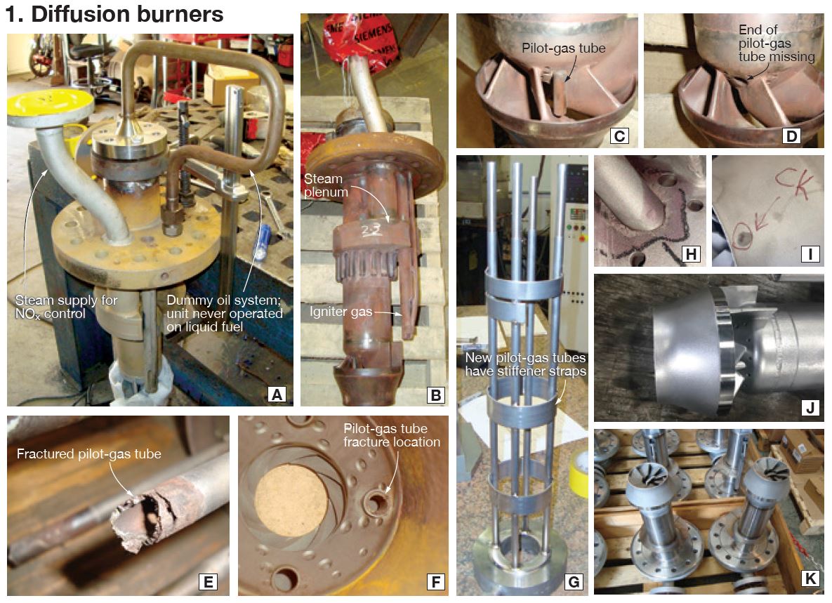
- Diffusion burners
Broken pilot tubes found during burner inspections must be repaired quickly to maintain outage schedule. Recall that four pilot tubes are installed in each burner (Figs A and B) to deliver pilot gas to the swirler (C) for stabilizing combustion while in premix operation. For the case illustrated, not all pilot-gas tubes were in evidence (D), some having fractured (E) just above the hole through the swirler casting (F).
Metallurgists, including Curtis, suspected stress corrosion cracking of the 300-series stainless steel tubes was the underlying cause of the pilot-tube failures and selected Inconel-600 as the replacement material (G).
The burners at this plant exhibited other damage as well—such as severe oxidation of carbon-steel oil-burner flanges, which were weld-repaired and finish-machined as part of the project. Also of note, the thermocouples provided by the OEM were not replaceable without disassembly. Eta Tech developed a replaceable T/C mod, now included among APG’s solutions.
Perhaps the biggest challenge on this project, Curtis said, was completing the repairs, installation, and final inspection within a 12-day window to avoid an outage extension. The plant had no spare burners so replacement of the pilot-tubes was the only viable option.
At other plants, swirler casting defects—including cracks and porosity (H and I)—have been found. No problem, generally speaking, according to Curtis, APG can now manufacture new and replace swirlers, as well as diffusion-burner assemblies (J and K).
Pre-mix gas distributors
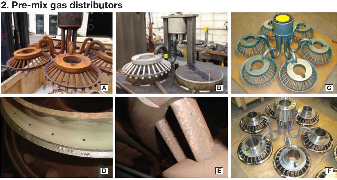
Curtis next discussed repairs to the legacy H-style gas distributor. He seemed particularly proud of the procedure Eta developed to replace corroded “S” bends (Fig A), originally fabricated from 16Mo carbon steel, with P11 material of increased wall thickness.
The company’s fixture enables the making of precision repairs (B) as an alternative to purchasing a new distributor assembly from the OEM for significantly more money. A corrosion-resistant coating adds a measure of protection (C). Note the notches in the six distributors to accommodate the igniter tube visible in Fig B in Section 1 on diffusion burners.
Curtis mentioned seeing “S” tubes lose up to 40% of their wall thickness, much like HRSG tubes subjected to FAC. The weld process used, he continued, has been qualified with sample cut-ups and hardness traverses as-welded and after stress relief. Welds made in refurbishing gas distributors are stress-relieved, x-rayed, and liquid-penetrant inspected.
Over the last several years, most V84.2 units in the US fleet have upgraded to the so-named HR3 style of distributor, where pre-mix gas is delivered to each of the six “heads,” a/k/a diagonal swirlers. Fuel gas enters the air stream through holes in the airfoils in each head. Damage mechanisms associated with this design include fretting wear of the flange on each head (D) and corrosion of the airfoils (E). Should airfoil corrosion or other damage get too severe for repair, APG offers a new HR3 (F).
Kearney, a former plant manager, interjected that an additional “hot button” on this component today is the cleaning of internal passages. He said the OEM brings an ultrasonic cleaning bath to the plant for this purpose, but users have told him this method is ineffective and expensive. Plus, disposal of spent cleaning solution can be problematic in some locations. APG offers an offsite thermal cleaning alternative (takes about a week from removal to reinstallation).
Compressor diaphragms
Kearney said many V84.2s he’s familiar with have never had compressor diaphragms removed for inspection or repair. Simple erosion and corrosion over time is to be expected and not much of a concern beyond reducing compressor efficiency.
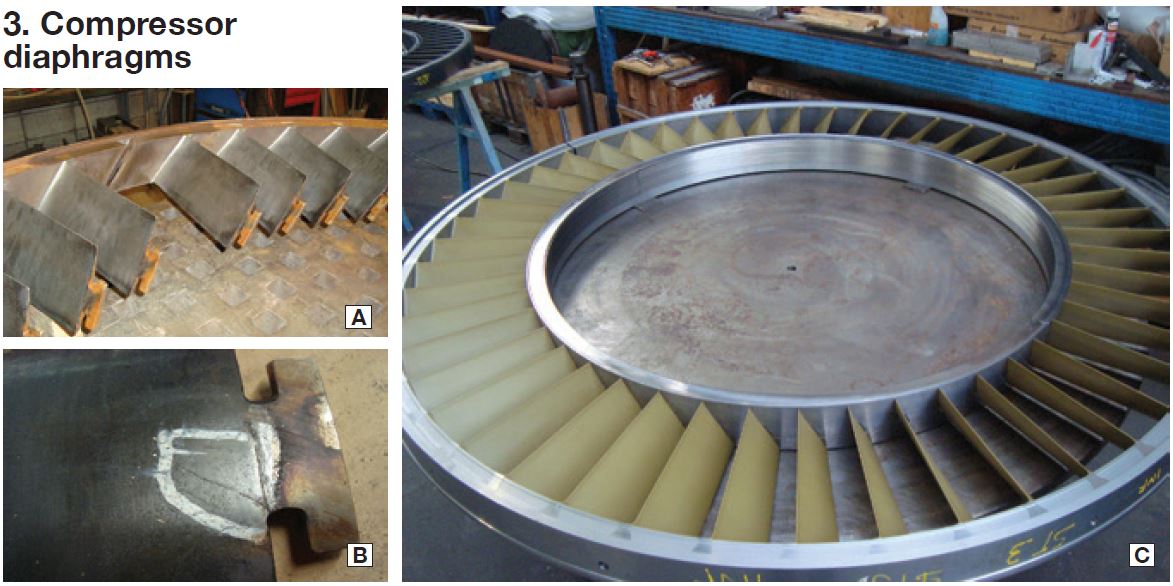
However, diaphragms are prone to developing airfoil cracks emanating from the inner tenon, where the vane attaches to the assembly’s inner ring (Figs A and B). Curtis concurred with what he believes is a general feeling among users that the OEM has overly conservative repairability criteria on the number/sequence of cracked vanes that allow or disallow full diaphragm repair. Eta Tech, and now APG, routinely extend these criteria if analysis confirms the decision.
In the event repairs are not practicable, APG has the engineering/manufacturing know-how to make all diaphragm stages (C). In fact, Curtis said, new coated diaphragms were delivered to customers last year.
Fuel-oil burners
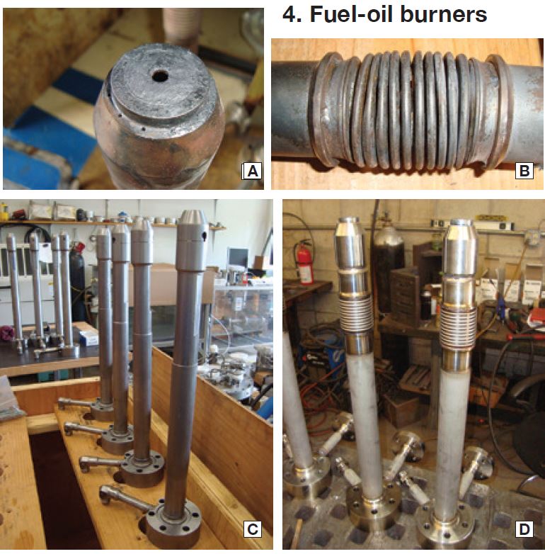
According to Kearney, Siemens manufactures two different styles of fuel-oil burner lances: oil only and oil/water, the water circuit for NOx abatement and/or power augmentation. The OEM design relies on shrink fits to separate and seal the water and oil flow channels, Curtis added, connections that can fail in service and cause coking (Fig A), bellows damage (B, oil/water design only), unusual spray patterns, and flame-tube damage.
Burners that are repairable are completely disassembled by APG, cleaned, parts replaced as necessary, reassembled, and flow-tested. When repairs are not cost-effective APG offers new. It manufactures both styles of burners (C and D). Excellent performance in service is claimed.
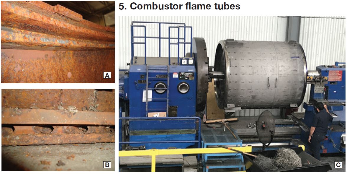
Combustor flame tubes
The OEM’s design of combustor flame tubes has evolved over the years to address service-related material distress. The upper F-ring (Fig A) and the lower tile support ring (B) are made from carbon steel and are exposed to combustor temperature—thereby making them prone to severe oxidation damage.
Curtis recalled mechanical design changes made by the OEM to protect the F-ring—changes requiring the purchase of new-style combustor dome plates and relocation of combustor-brick “removable” rows. He said Eta Tech took a different approach: Make F-rings and tile support rings from an oxidation-resistant alloy that did not require flame-tube or dome-plate configuration changes, and add TBC to mounting hardware for combustor-brick “removable” rows. APG can supply all of the hardware used in the combustors, including the ceramic bricks.
Recently, APG has manufactured and delivered new flame tubes with rings of upgraded nickel-based alloy. Plus, it has repaired and upgraded used flame tubes with the upgraded rings (C).
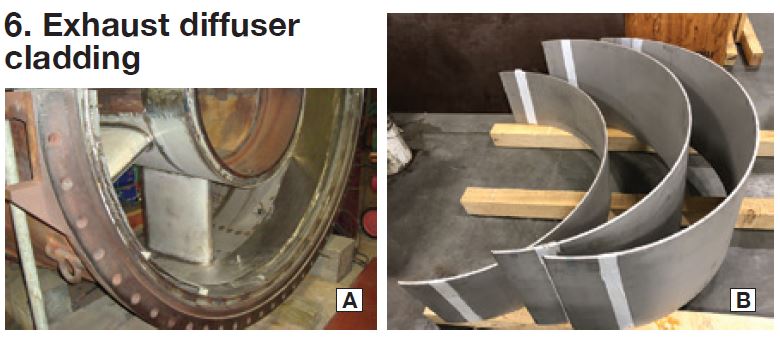
Exhaust diffuser cladding
The exhaust diffuser, or frame, for the V84.2 has inner and outer cylindrical and conical sections and airfoil-shaped struts that support the turbine end-bearing compartment (Fig A). Replacement of the stainless-steel liner for the diffuser is necessary when embrittlement occurs and cracks occur, and poor weldability makes repair difficult. For users opting to replace damaged components, APG offers individual sections of cladding (B) or full-replacement cladding “kits.”
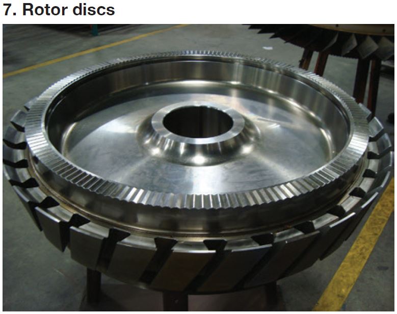
Rotor disks
Looking ahead, Curtis said that as V84.2s approach 200,000 equivalent operating hours, compressor (photo) and turbine rotor discs, and hollow shafts, become candidates for retirement. Anticipating the coming demand, APG has completed all necessary engineering work and supplier qualification for the supply of new rotor components. The company is expecting orders for delivery in late 2020 and beyond.
ARNOLD Group
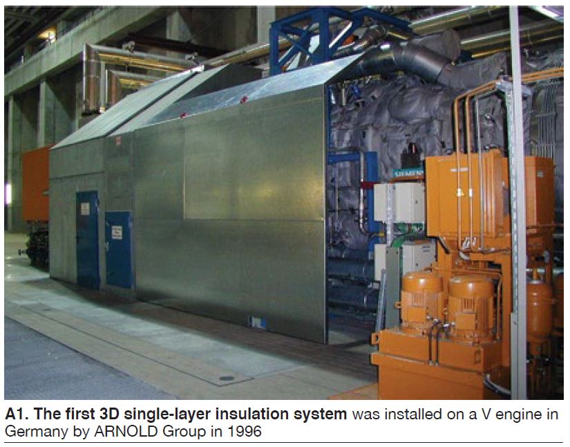
ARNOLD Group is well known worldwide for its gas- and steam-turbine insulation solutions; in Europe and Asia also for its powerplant rotating-equipment and valve field-services capabilities (www.arnoldgroup.com). The company’s history in gas-turbine insulation, the focus of this report, goes back nearly a quarter of a century to the installation of the first Arnold 3D single-layer system on a SGT-1000F (V64.3A) machine at EnBW Energie Baden-Wuerttemberg AG’s 1200-MW Altbach/Deizisau combined heat and power plant (Fig A1).
Since then, more than 300 V-type engines—most V94/84.2s and .3As—in Europe, Asia, Africa, the Middle East, and the Americas have been insulated by Arnold. These units were manufactured by Siemens or its licensees—including Ansaldo Energia (Europe and Asia), Shanghai Turbine (China), and LMZ (Russia). Many other models of gas turbines also wear Arnold.
Revisiting Altbach, in more than two decades of service only 14 blankets have required replacement on that unit. Having an Arnold technical field advisor onsite during outages is said to have contributed significantly to this excellent service history: The TFAs made certain that the hundreds of numbered insulation blankets required for a typical E- or F-class gas turbine to assure easy access to critical instrumentation, borescope holes, etc, were removed, handled, stored (temporarily), and replaced correctly.
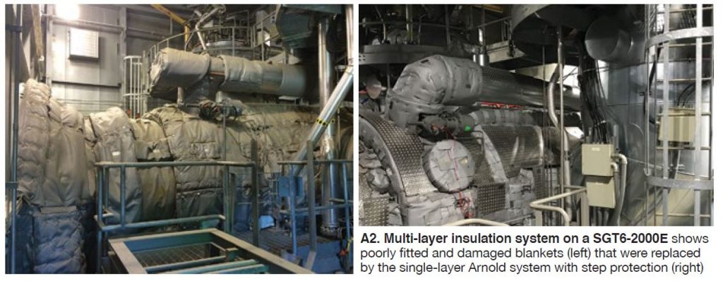
To date, Arnold has replaced the insulation on seven SGT6-2000E gas turbines in the US (Fig A2), with a few more projects in the pipeline for 2021. No SGT6-4000F machines have been refurbished in North America yet, but several SGT5/6-4000Fs in South America have been.
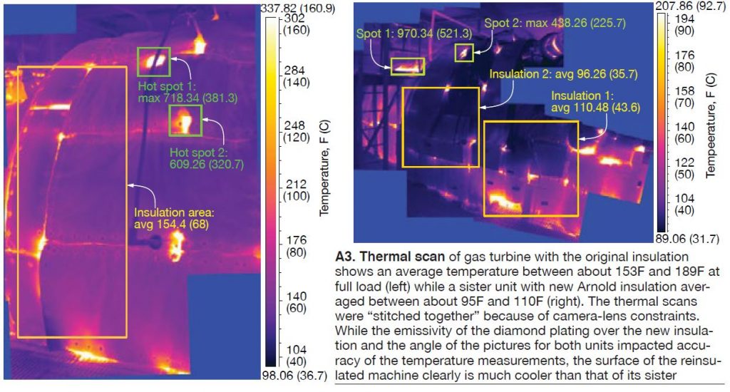
Why replace insulation. Pierre Ansmann, global head of marketing for ARNOLD, says it’s only a matter of time before the economics of electric power generation suggests US owner/operators consider seriously replacement of the original insulation on their SGT6-4000Fs and other SGT6-2000Es.
Loss of earnings results from poor design/installation of turbine insulation and/or premature wear and tear of blankets. A plant’s balance sheet can be impacted negatively by reduced power production, contractual penalties, damage to mechanical and electrical equipment and instrumentation, and shorter outage intervals.
Insulation can wear out faster than you think, he says, particularly that installed on gas turbines with issues dictating frequent removal of their upper casings. If your unit was purchased during the “bubble” of 1999 to 2004 and still has its original insulation, Ansmann recommends conducting a thermal survey (Fig A3) to evaluate its effectiveness, keeping personnel safety in mind.
Benefits of replacement typically include less heat loss, less noise in the enclosure, a reduction in insulation removal/replacement time during outages, greater flexibility in maintenance scheduling, and longer lifetimes for in-package equipment—especially heat-sensitive motors, wiring, and instrumentation sometimes associated with unit trips.
Note that all the V engines in the US that have upgraded their machines with Arnold insulation began commercial operation during the bubble. They reported having done extensive repairs to the original blankets, or replacing them, during every outage. As-built performance remained elusive, however. In these cases, marginal materials of construction, and the use of blankets well beyond their design durability limits, made the decision to replace a relatively easy one.
As a rule of thumb, Ansmann figures standard insulation systems typically perform as-designed for three to five off/on cycles, not close to Arnold’s guarantee of 15 cycles when removal and reinstallation are done correctly. After about five outages, he says, users with insulation made by others often find blankets difficult to reinstall properly—especially where they overlap.
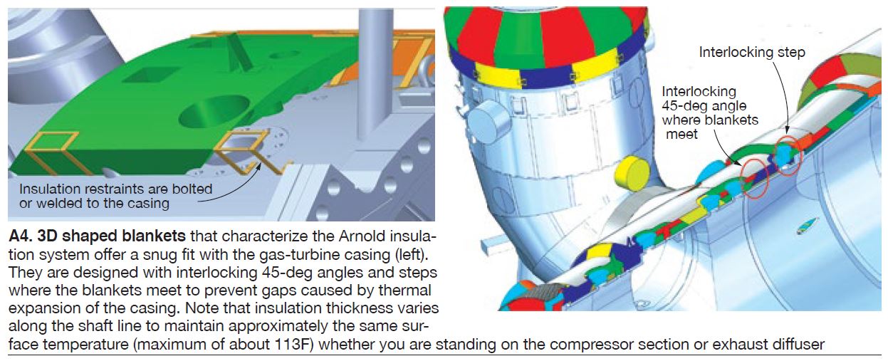
This is particularly true when blankets must be held in place by pins welded to the casing. Pins are not used in the Arnold insulation system: Rather, interlocking high-temperature-resistant blankets, cut to conform to the turbine surface (Fig A4), are held in place by industrial Velcro® and a unique support system that is secured by studs welded to the casing. You may recall that pins sometimes are removed during maintenance for safety concerns, or otherwise; if not replaced, there’s little chance of getting blankets tight.
Other concerns of plant personnel regarding marginally designed and ageing insulation systems, in Ansmann’s experience, include these:
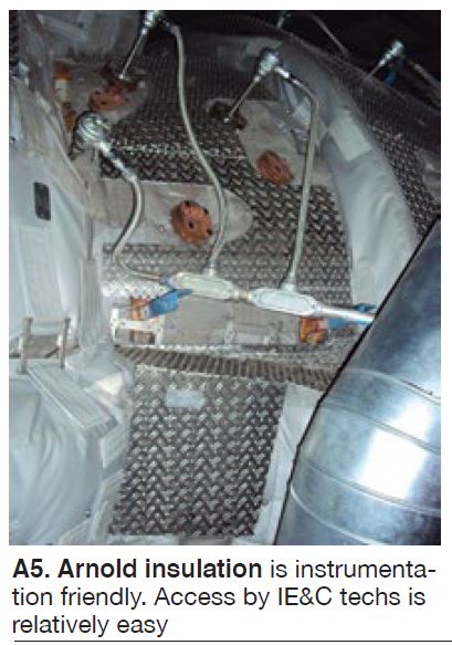
- Insufficient protection for thermocouples, borescope inspection ports, and instrumentation (Fig A5).
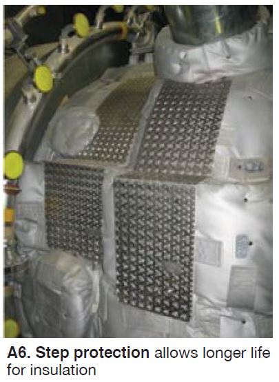
- Activities that require walking on insulation can move blankets out of position and/or release fibers—a possible health threat. Arnold’s aluminum deck-plates-style step protection system reduces the possibility of insulation damage during maintenance (Fig A6).
- Sagging of insulation can cause uneven thermal expansion of the casing.
Key steps in insulation replacement
The success of any engineering project depends on rigorous planning. Pierre Annsman, a member of ARNOLD Group’s management team, told the editors at a recent user conference that a good first step in an insulation replacement project is a photo session with the candidate turbine.
A laser scan allows the company’s design and manufacturing personnel to adjust existing shop patterns for a particular engine model to the unit being reinsulated. Bear in mind that in-package piping and equipment arrangements vary.
Adjustments to the manufactured blankets may be required in the field to accommodate such things as flange positions, thermocouples, borescope inspection ports, etc. This work is done by experienced technicians—think of them as tailors—equipped with the proper sewing hardware.
The most economic scheduling for insulation replacement is about 20 single-shift weekdays with two TFAs and six local insulators. Calendar time can be reduced, of course, by working weekends, increasing the number of TFAs, and running double shifts. Turbines typically are reinsulated during major or hot-gas-path inspections in parallel with mechanical work. Insulation is not on the outage critical path.
Work begins when the turbine is cold and proper scaffolding is installed, if necessary. Insulation is removed by a local contractor, typically in a day and a half, and plant I&E technicians remove all instrumentation. About another two days is required to cut off all pins installed to accommodate the original insulation system, grind the pin stubs smooth with the casing, and brush/vacuum the unit and package clean.
Respiratory protection is highly recommended during this work. It’s also a good idea to have a health and safety engineer to measure the concentration of dust in the package to assure safe working conditions.
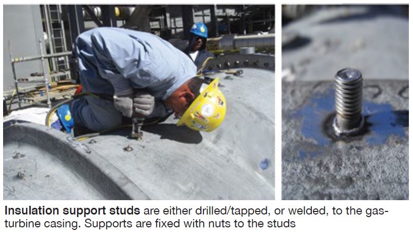
Installing the retention brackets and studs (photo) required to position and attach the new insulation is the next step. If the casing is forged steel, these components can be welded to the casing; if cast, drilling and tapping are required. Both procedures are done in accordance with the OEM’s recommendations. At this point, may be a good idea to laser scan the unit again to pin-point the location of all attachments, just in case.
Final steps: Install the new insulation system, have I&E techs replace the instrumentation removed previously, and dismantle temporary scaffolding.
Sulzer
Sulzer’s Rotating Equipment Services unit—formerly Sulzer Turbo Services—offers a wide range of inspection, shop, repair, and manufacturing services for gas and steam turbines, generators, pumps, compressors, and other power and process equipment. The company actively supports the V94/84.2 and V94/84.3A fleets through its participation in user meetings here and internationally. It has major shop facilities worldwide to serve powerplant owner/operators.
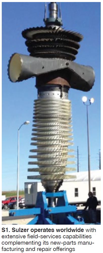
Not familiar with Sulzer? Tour the company’s website at www.sulzer.com for an overview of shop capabilities pertinent to your equipment—including physical and metallurgical inspections, welding, heat treatment, machining, turbine and compressor coatings, rotor disassembly/reassembly, etc. Sulzer offers field-service (Fig S1) and new-parts manufacturing to complement its repair offerings.
Most of Sulzer’s efforts with regard to V engines focus on the Siemens SGT5/6-2000E and Ansaldo AE94.2 machines. Aftermarket services for about two-thirds of this market segment are “competitive”—that is, not influenced by an OEM’s long-term services agreement. By contrast, Siemens says 80% of the SGT5/6-4000F engines it has supplied are governed by an LTSA.
While Sulzer, like ARNOLD Group and APG, does perform repairs and field services for some 94/84.3A owner/operators, the manufacture of major new parts is not included among its current offerings.
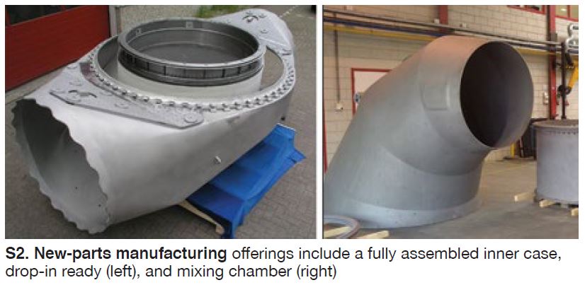
New parts. The company makes the following parts for legacy 94/84.2 engines: compressors; inner casings, mixing chambers, and flame tubes for the combustion section (Fig S2); and Row 3 turbine blades. Plus, for the 94.2 only: combustion-section heat shields and fuel nozzles, as well as turbine blades for Rows 1 and 2 and vanes for Rows 1, 2, and 3.
For 94/84.2 models through Version 7: Combustion-section inner casings, mixing chambers, and flame tubes; turbine vanes for Rows 1 and 2. Additionally, new fuel nozzles are available for 94.2 models through Version 7.
New parts are said to be “ready to drop in,” having the same form, fit, and function as those supplied by the OEMs.
Mods and upgrades for critical 94/84.2 parts are a significant part of Sulzer’s value-add offerings. Some examples follow:
- Relocation of the F-ring to mitigate burnout of tile clips by moving the holders to a region of lower temperature, in addition providing easier access to tiles for replacement.
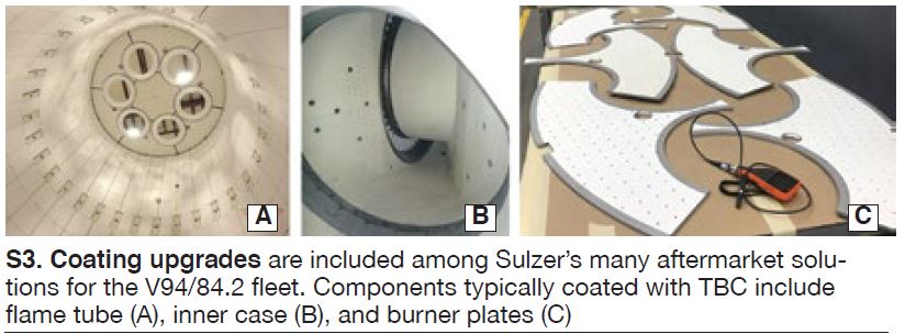
- Coating upgrades for flame tubes (Fig S3). This includes adding thermal barrier coating (TBC) to burner plates, bezel rings, and F-row tile clips; plus, depositing chrome carbide (CrC) on bezel rings and burner plates.
- Flame-tube upgrades include an Inconel overlay for F-rings and Hastelloy-X tile support rings.
- Improved cooling-hole pattern for flame-tube burner plates. Also available are larger plates and a material upgrade to Haynes 230.
- Inner-case upgrades include TBC coating of the hot-gas-path surface and CrC coating of inlet collars.
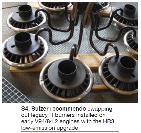
Burners, etc. Sulzer recommends swapping out legacy H burners with the HR3 low-emission design (Fig S4), which is said to offer the following benefits:
- More stable combustion, primarily because of better mixing of the fuel gas with combustion air.
- Increased resistance to flame flashback. One reason: The higher velocity of the fuel/air mixture through the HR3’s optimized flow channel reduces the probability of the flame traveling upstream.
- Corrosion-resistant gas supply piping minimizes leakage risk and reduces maintenance.
- Reduced NOx emissions. The better mixing of fuel and air inherent in the HR3 design eliminates flame hot spots (emissions spikes) associated with the H burner.
Sulzer also actively promotes its E-UP program for the 94/84.2 fleet, which promises users a 5-MW increase in power output and a 0.8% efficiency improvement for retrofitting turbine Rows 1 and 2 blades and vanes with airfoils of its design. All incorporate what the company believes is an improved nickel-base superalloy (Rene 80), TBC coating system, and more efficient airfoil design.
The specific coating system selected depends on an engine’s operating conditions. Generally speaking, MCrAlY is used on the external surfaces of Row 1 and 2 airfoils because of its superior oxidation and corrosion resistance in both base- and peak-load applications. Use of TBC is optional where necessary to reduce metal temperatures and thermal gradients for improved protection against creep and fatigue. Internal surfaces have an aluminum diffusion coating to help prevent intergranular attack.
In addition, R1 vanes feature internal impingement cooling, re-staggered and optimized airfoil design, integrated cover plate with impingement cooling, and cut-back trailing edge. Highlights of the R2 vane design include tilted and optimized airfoil design, serpentine internal cooling geometry, and throttle sleeve to control the mass flow of cooling air.
For R1 turbine blades, enhancements include: cut-back trailing-edge design adopted from the 94/84.3A blade, serpentine internal cooling geometry, and squeeler tip.
The enhancements cited above are said to allow Sulzer’s Row 1 and 2 turbine blades and vanes to operate reliably in engines with turbine inlet temperatures of up to 1080C (1976F). CCJ


