


By Rishikesh Velkar and Bob Ott, NV Energy
NV Energy’s Silverhawk Generating Station experienced repetitive failures of cold-reheat (CRH) piping which were attributed to quenching of the pipe caused by leaking attemperators. The cause of the first failure, in 2013, initially was thought to be a flaw in a shop weld. Three years later the plant suffered three more failures within a 12-month period and performance data were collected to determine the root cause of the problem.
The Silverhawk CRH piping failures occurred at the high pressure (HP) bypass to the CR tee, requiring multiple repairs at significant unbudgeted cost. The failures caused forced outages and loss of availability hours.
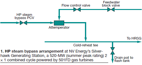
In a typical combined cycle, after the gas turbine is started and the steam begins to absorb energy from the exhaust-gas stream, it flows from the heat-recovery steam generator through the HP piping and is bypassed to the CRH line via the bypass pressure control valves (PCVs), as shown in Fig 1. The HP bypass lines have attemperators on the line to mix feedwater into the bypassed steam and control the temperature of the fluid in the line. Attemperator water flow is controlled using a flow-control valve and a block valve.
Described below are the failures that the plant has experienced since 2013:
- July 2013. The cold-reheat tee failed on Unit A, identified by water and steam leaking from the piping. The loss in availability attributed to repairing and testing the piping was 55 hours.
With the unit shut down, insulation was removed in the tee area and a visual inspection was conducted. The downstream weld connecting the tee to the CR piping had a clear indication of a crack, which was confirmed by magnetic-particle and dye-penetrant testing (Fig 2).
The indication was 5 in. long on the pipe OD, 24 in. on the pipe ID. During radiographic testing of the weld after repairs, another crack (Fig 3) was found on the opposite side of the tee in the same weld that had been repaired. This 3-in.-long circumferential crack was repaired as well.
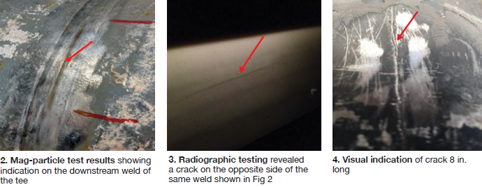
- March 2016. The CR tee on Unit A failed again on the downstream weld connecting the tee to the steam piping (Fig 4). Availability loss: 26 hours. The crack, confirmed using dye penetrant, was 8 in. long.
- September 2016. The CR tee on Unit A experienced its third failure, on the same downstream weld and in the same area as it did in July 2013. Availability loss: 18 hours. Two cracks, each about 10 in. long, were detected during an ultrasonic inspection. A visual indication of one crack is shown in Fig 5.
- January 2017. The CR tee on Unit B failed at the downstream end; availability loss was 20 hours. The crack, about 18 in. long, was found during an ultrasonic inspection (Fig 6).
Failure investigations
Investigation of the 2013 incident concluded the failure was caused by flaws in the shop weld and introduced during fabrication. Engineers believed that cycling of the unit could have exacerbated the problem because of thermal fatigue. After the second and third incidents in 2016, investigators confirmed that all three failures were caused by quenching of the metal by condensate.
Staff suggested two ways condensate might enter the CRH pipe and quench it:
The first, via the drain pot, by back-feeding through the flash tank header, which if unable to drain correctly would allow condensate to pool in the CRH line. This possibility was supported by a report from plant personnel who saw the flash tank overflowing a couple of years prior to this event.
However, backflow was ruled out after review of historian data. There was nothing to suggest the flash tank was overflowing and the drain-pot valve was functioning normally.
The second, via the attemperator and its associated block valve. This could not be verified by historian data because the feedwater flow meter was not working properly.
Engineers then decided to open a drain valve between the flow control valve (FCV) and block valve during normal operating conditions to see of the latter was leaking in the closed position. Water flowing through the drain valve confirmed this was the case. But it was not known if the FCV was leaking as well.
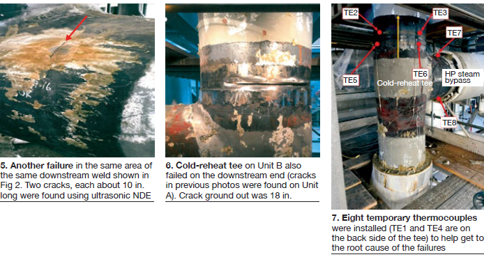
After the CRH tee on Unit B failed early in 2017, insulation was removed and eight thermocouples were installed temporarily on the tee to collect the data required for a true root-cause analysis (Fig 7). Six thermocouples were attached upstream and downstream of the weld, two of them near where the failure had occurred. The remaining two thermocouples were attached on the top and bottom of the HP bypass line connection to the tee.
Pipe temperatures were recorded during a Unit B start and when the plant was transitioning from 1 × 1 operation (Unit B gas turbine, its HRSG, and the steamer in service) to 2 × 1 service. Looking at Fig 8, note that as the unit heats up, the temperatures on the pipe slowly increase to 620F.
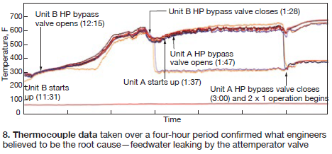
Now observe that during 1 × 1 operation, when the Unit B HP steam meets the required set point for it to flow through the turbine and the HP bypass valve closes, thermocouples TE7 and TE8 on the bypass side of the tee drop to approximately 300F. This confirms feedwater was leaking through the attemperator valves.
Furthermore, during the transition to 2 × 1 operation (when the Unit A HP bypass valve closes), thermocouples TE1 and TE4, where the failure occurred, drop down to about 360F. This means that during 2 × 1 operation there was a stream of water spraying in the area where the failure occurred, causing the metal to quench and contract.
Engineers decided to conduct a high-energy-pipe inspection during the spring 2017 outage. Prior to that outage, insulation was removed to prepare the surface of the pipe for an NDE inspection. An infrared camera was used to gain a better understanding of the temperature transients across the tee. The pictures clearly showed the attemperator leak was cooling a portion of the pipe (Fig 9).
Conclusion
A significant area of the pipe was cooled to around 350F to 400F, causing that section of pipe to contract while the remainder was expanding. The cool area overlapped the previous failure areas. Engineering analysis revealed the failures occurred from the inside surface outward in fatigue. The information gathered proved that the failures of the weld at the tee was from quenching caused by leaking attemperator valves.
Final steps. During the 2017 spring outage the following actions were taken:
- Attemperator block valves were replaced to prevent feedwater leak-by.
- Permanent thermocouples were installed on the HP bypass line downstream of the attemperator to alarm when steam temperature falls below saturation—this to alert operations personnel to potential attemperator block-valve leak-by and abnormal operating issues.
After these action items were implemented, the thermocouples on the bypass line indicated a steam temperature of more than 600F, confirming that the new block valves prevented feedwater from entering the steam pipe.
Finally, similar issues were found at another plant in the NV Energy fleet that had experienced piping failures—although the piping configuration was different. An infrared camera was used to confirm the quenching and isolation valves were restored to prevent these damaging conditions. CCJ
About the authors
Rishikesh Velkar is plant engineer at NV Energy’s Silverhawk Generating Station, located about 35 miles north of Las Vegas. Bob Ott, the utility’s manager of generation engineering and technology, is based at headquarters.