


Only a few months away from its 40th anniversary, CTOTF™ never stops evolving to meet the industry’s information needs. Perhaps that’s why it’s the most senior user group—by more than a decade—serving gas-turbine owner/operators. Jack Borsch, VP O&M at Colectric Partners, was not in the chairman’s chair very long when he began making organizational adjustments. Recall that Borsch replaced Bob Kirn at the helm last fall, when Kirn retired from TVA.
One of the first things Borsch did was to build more structure into the aeroderivative portion of the organization’s program, putting the various engines under one umbrella and assigning experts to guide the coverage for each of the four OEMs involved: Pratt & Whitney (now PW Power Systems), Rolls-Royce, GE, and Solar Turbines. Here’s how the CTOTF Aero Roundtable team is arranged:
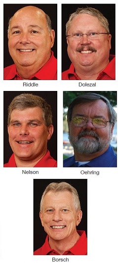
- Senior chair: Jim Riddle, production manager for CAMS-SEEDCO LLC.
- PWPS chair: Greg Dolezal, maintenance manager for Iberdrola Renewables’ Klamath Cogeneration.
- Rolls-Royce chair: John-Erik Nelson, principal mechanical engineer, Braintree Electric Light Dept.
- GE chair: Dennis Oehring, director of field services and O&M for ProEnergy Services.
- Solar chair: William Chen, PE, operations engineer for the LA County Sanitation Districts’ Calabasas Gas-to-Energy Facility.
 The CTOTF spring meeting focuses on Rolls-Royce engines and the PWPS FT8; the fall meeting on the PWPS FT4, GE LM2500/5000/6000, and Solar GTs. If you are responsible for one or more of the thousands of Solar machines populating the electric-power and oil-and-gas industries and looking for an independent forum that encourages information exchange among users, this may well be your best option. Consider registering for the fall meeting today. The remainder of this article offers a flavor of a typical program for Solar engines, based on information shared at last fall’s meeting.
There were three prepared presentations and a discussion forum at the fall 2013 Solar Roundtable. Ken Mertz of AAF International reviewed the benefits of HEPA filtration for maintaining compressor efficiency while Marcus Bastianen, PE, Everest Sciences Corp, discussed the principles of hybrid inlet cooling for gas turbines to extract maximum power and efficiency from small- and medium-size engines. Finally, John Kyser, associate civil engineer for the East Bay Municipal Utility District, shared lessons learned in bringing East Bay’s first GT into commercial service.
Users generally think HEPA filters are new to gas turbines in power generation service, but that’s not so. AAF International, for example, installed its first HEPAs on a land-based GT (LM1600) in mid-1992. Earlier use was offshore. Mertz began by providing perspective on the quantity of particles captured by a HEPA filter that would penetrate a conventional fine-dust filter. Efficiency is what’s reported, he said, but penetration is what’s important.
The filter standard you’re probably most familiar with is ASHRAE 52.2. It ranks particle capture capability using a MERV (Minimum Efficiency Reporting Value) rating from 1 to 16. The most efficient filters for preventing fine particles from entering the compressor are at the upper end of that scale. Your GT filters likely are rated MERV 14 or 15. The first removes from 75% to 85% of the particles in the inlet air between 0.3 micron and 1 micron; MERV 15 captures 85% to 95%. Both MERV 14 and 15 remove more than 90% of particles 1 micron and larger.
But an important point to keep in mind is that the particles of greatest concern regarding compressor fouling are smaller than 0.5 micron. This means any filter with a MERV rating could allow all particles smaller than 0.3 micron to pass through it and still meet the ASHRAE specification. The normal distribution of particles typically found in urban ambient air indicates that there are 100 times more 0.1-micron particles than 0.5-micron particles.
HEPA filters are rated according to EN1882 (a European standard), which is based on the minimum capture rate of the most penetrating particle size. MPPS, in plain English, is the particle size that has the lowest capture efficiency for the media tested. The defining size usually is in the range of 0.05 to 0.2 micron. The standard requires that MPPS particle capture be at least 99.5% for an E12 rarting. In the particle size range of greatest interest—up to 0.5 micron—a Univ of Michigan study showed that a new E12 HEPA captured 200 times more particles than a new MERV 15
With the session focus on the Solar Mercury, Mertz offered a side-by-side comparison of two Merc 50s located about 10 miles inland from the coast and subjected to an occasional marine layer. One engine was equipped with MERV-13-rated cylindrical/conical-style inlet filters, the other E12 with pre-filter wraps. While the filter houses have pulsing capability, that feature is not used.
Test results based on 4500 operating hours were extrapolated to 8000 hours and the following conclusions were drawn:
- The E12-equipped engine produced 3.6% more power than the GT with MERV 13 filters.
- Heat-rate improvement favored the E12 engine by 2.32% over the unit with MERV 13 filters.
Mertz’s presentation is available at forums.ctotf.org.
Indirect/hybrid inlet cooling. Everest Sciences’ air-inlet solutions are particularly well suited today to gas turbines up to about the size of an LM2500, a fact reflected by the more than 10 projects the company has in service. Bastianen offered case studies on three Solar machines given the session’s focus: a Taurus 60 generating power in the Southwest, a Mercury 50 on the West Coast producing power from the combustion of landfill gas, and a Taurus 70 in pipeline compression service in the Northeast.
The speaker described the following three turbine inlet cooling systems available from Everest Sciences:
- ECOCool reduces the temperature of ambient air by evaporation in a high-tech crossflow heat exchanger. Cool air leaving the crossflow exchanger then is used to cool ambient air for combustion in an indirect air-cooled heat exchanger. The key point: Combustion air is cooled, and its density is increased, without adding moisture. Next, the combustion air passes through a wetted-media evap cooler before entering the compressor.
- ECOChill has the same first two steps as ECOCool—referred to as the Everest Cycle—but it uses a chiller instead of an evap cooler as the final step. Note that the chiller here is substantially smaller than one used in a conventional chilling system because some of the cooling already has been done by the Everest Cycle. The smaller the chiller, the more net power output and the higher the net engine efficiency.
- Hydro-FlexCool is a variant of the Everest Cycle (the first two steps in ECOCool). Its indirect evaporative heat exchanger uses brackish or reclaimed water and air as the first step in turbine inlet cooling.
Case study 1: For the Taurus 60, the net yearly economic value associated with using ECOCool for 11.2 months is more than half a million dollars. The engine produces an additional 3.1 million kWh (net) annually—roughly split 2:1 between off-peak and on-peak production. Average heat rate and emissions for the incremental power is 25% less than for the base case.
Case study 2: For the Mercury 50, the net yearly economic value is more than $350,000 using ECOChill for 10.2 months. The engine produces an additional 2 million kWh (net) annually, nearly 30% of that on-peak. Average net heat rate and emissions for the incremental power is 19% less than the base case.
Case study 3: For the Taurus 70, the net yearly economic value is more than $1.2 million using ECOChill for 6.1 months. The engine annually produces almost 3.5 million shp more with this inlet cooling solution. Average heat rate and emissions for the incremental power is 21% less than for the base case. Unlike case studies 1 and 2, here fuel costs are passed along to the customer, improving economics and enabling project payback in less than one year.
Commissioning a Merc 50. Kyser’s 4.6-MW machine joined three 2.1-MW recips operating at the Oakland wastewater treatment plant since 1986. All generating units burn digester gas with a heating value of about 600 Btu/scf. About half the gas comes from sewage, the remainder from commercial wastes (winery, restaurants, etc) delivered by truck.
East Bay’s treatment plant consumes about 4.8 MW in handling and treating the approximately 60-million gal/day of wastewater flow (dry weather), plus trucked wastes. The original diesel/generators together could only manage about 4 MW on average; power purchased from PG&E made up the shortfall.
With biogas available and being flared, the utility decided to increase its generating capability. A gas turbine was selected as the prime mover because of its emissions and reliability advantages over the diesel alternative. Design began in July 2007 and the turbine/generator entered commercial service in November 2011.
A new gas conditioning system, rated at 3000 scfm, was installed as part of the turbine project to serve all generating units. It removes siloxanes using activated carbon. Clean digester gas exiting the conditioning system at about 6 psig is compressed to 230 psig for the Merc 50, and moisture is removed. At full load, the Solar engine consumes about 1200 scfm of the 2000 scfm of biogas produced by the digesters. The balance is burned in the diesel/generators and excess power is exported to PG&E. A heat-recovery unit in the turbine exhaust stream is used to warm water for the digesters.
Operating a generating facility on biogas can be challenging because gas production varies with waste flows and energy content. One slide showed gross electric production during a two-week period in spring 2012. Average generation was about 6 MW over that time but there were a couple of days when the plant produced less than 4 MW and a few days when it generated more than 8 MW.
The most difficult problem facing East Bay during the Merc 50’s first year of operation was ablation of fuel-injector effusion caps and collateral damage to turbine blades downstream. The issue was first detected during a routine inspection by the OEM in July 2012. A laboratory investigation at the end of August concluded that the injector damage was caused by exposure to high temperatures. The melting temperature of the effusion cap was 2400F, with the tip expected to operate at about 1600F. Laboratory tests found no evidence of corrosion or external contamination—from siloxanes, for example—in the combustion chamber.
Eight new injectors were purchased and installed; two of them were equipped with thermocouples behind their effusion caps. Data obtained revealed that temperatures reached from 1700F to 1850F during operation. The control system was programmed to trigger a shutdown at 1800F. Investigators believed that the original 6% pilot setting allowed flame too close to the injector tip.
That certainly contributed to the damage, but it was not the only cause. Engineering and testing over the next several months eventually solved the problem. During that period, injectors were replaced three times. Dialing back of the pilot to a 4.5% setting was one of the first corrective steps taken, but that fell short. The solution ultimately was an injector designed specifically for medium-Btu gas and a 1.5% pilot. Operating temperature of the upgraded injector is in the range of 1150F to 1250F. The new hardware had been in service for five months at the time of the presentation with no problems reported. CCJ