


Make it Right!
Air inlet houses seldom get the respect they deserve. Properly equipped and maintained, they help assure maximum output and high availability of your gas turbines (GTs). Yet they are almost an afterthought at many plants, the focus being on rotating equipment.
That’s interesting because everyone reading this article knows their GTs require fuel and air to operate. And that there’s relatively little you can do to fuel delivered by pipeline to improve engine performance and reliability except possibly heat it up a bit and remove particulates and moisture with fairly standard equipment.
You prepare air for combustion in much the same way: filter, add or subtract moisture, heat or cool. But there’s a great deal most owner/operators can do to the air their compressors receive to improve overall plant performance. This report begins with suggestions on how to conduct a proper inspection of the air inlet house and decide what improvements are required and how quickly to do them.
Air filtration is next. It offers a backgrounder on the subject as well as the latest experience on the use of HEPA (high-efficiency particulate air) filters. They have the potential for keeping your compressor pristine and possibly eliminating the need for online and offline water washing.
Of course, the specific benefits of HEPA filters to your plant—such as little, if any, degradation in compressor performance over time—must outweigh their initial cost, which can run four or five times the price of conventional filters. Plus, personnel may be required to make more frequent inspections and be more vigilant about maintenance of the air inlet house, because air bypassing the filters would compromise compressor cleanliness.
Inlet cooling is a sure way to boost power output, but the effectiveness and value of a given method—evaporative cooling (media or fogging) or chiller—are influenced by ambient conditions, operating requirements, and commercial considerations. Evap coolers are most common and may be the easiest to operate and maintain. But care and upkeep, often forgotten, are required to maximize their cooling potential and avoid issues associated with carryover, poor water treatment, etc.
Fogging and its close relative, wet compression, often are criticized because they inject free water into the air stream. Many GT users fear that slugs of water may enter the compressor and damage the engine. Those with the greatest concerns seem to be owners of GE F-class machines, many of which have first-stage compressor blades that are particularly sensitive to moisture and easily damaged by direct impingement of water droplets.
But as with most everything, the selection of quality fogging equipment and its proper installation and maintenance are critical to achieving expected performance. Sizing and orientation of spray-nozzle holes, and the location/orientation of spray nozzles, are important considerations.
Chilling is well known for its ability to deliver air at 50F, or less, to maximize power production. However, it often is not considered seriously by merchant generators with energy-only contracts because of the relatively high capital cost and power drain.
But chilling can provide significant benefits to owners with contracts for capacity and some other ancillary services. Proof: Several post-bubble combined cycles recently have converted from evap cooling to chillers. The value proposition is improved when a thermal energy storage (TES) tank is integrated into the chilled water system. Another benefit of chilling: It reduces the airborne emissions per kilowatt-hour produced.
As you read this report, keep in mind that there may be very good reasons that your gas turbines’ air inlet houses were (1) fabricated of materials not ideally suited for the plant location; (2) equipped with filters generally not recommended for ambient conditions at the plant site; and (3) not outfitted with the most effective cooling system for your operating paradigm.
Most often the decisions were purely financial; overriding goal was to get the plant in service as fast as possible and for the lowest cost. Long-term performance made little sense for a facility that probably would be flipped in the near term.
Your challenge under new ownership, and probably a different contractual arrangement with the ISO (independent transmission system operator), is to meet expectations with an air inlet system that may not be conducive to the goals. Make it right! As you’ll see from the case histories included here, judicious upgrades and modifications can offer significant returns.
Inspection
What to look for and where
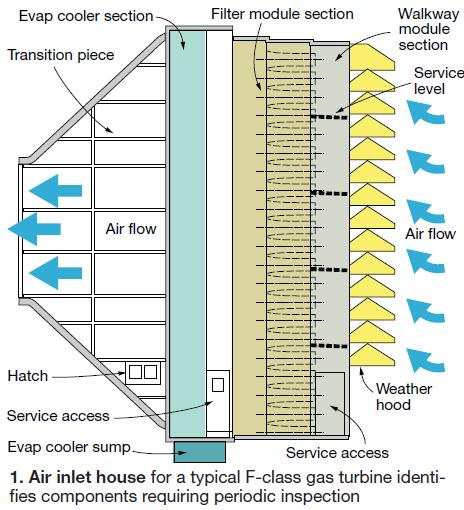
Air enters the gas turbine via structure that is referred to most often as the filter house, air inlet house, or inlet air house. In reality none of those names truly describes the function of this integrated package of systems and components vital to achieving GT performance and availability goals (Fig 1).
More accurate would be “gas turbine inlet-air conditioning facility.” But for simplicity’s sake the editors have opted for “air inlet system,” which is what Donaldson Company Inc, Minneapolis, a leading supplier of GT filters and related components, calls it.
Judging from the open discussion at various user group meetings, there doesn’t seem to be an “industry bible” on inspection and maintenance of air inlet systems. What you hear in these sessions typically is common-sense give and take: Here’s what we found, here’s how we found it, here’s what we did to correct the situation. Nothing wrong with that, of course, but it only benefits those present in the room.
David Brumbaugh, founder and owner, DRB Industries LLC (www.drbindustries.com), Broken Arrow, Okla, has an extensive background in air inlet system inspection and maintenance. He is a member of ASHRAE (American Society of Heating, Refrigerating and Air-Conditioning Engineers) and is certified by the National Air Filter Assn as an Air Filtration Specialist.Hopefully, the methods and ideas offered here will help those who have not had the opportunity to share experiences with deck-plates personnel outside their respective plants. Most of the material below was compiled from notes taken during individual discussions with the following people:
- Barry D Link, aftermarket sales manager, Donaldson (www.donaldson.com).
- William Stacey Davis, Turbine Maintenance & Plant Services LLC (wdavis34@satx.rr.com), spent 10 years on the front lines of combined-cycle plants before forming his own consultancy at the end of June. Most recently he was plant manager for maintenance and outages at Guadalupe Power Partners—two 2 × 1 7FA-powered combined cycles in the PSEG Texas portfolio.
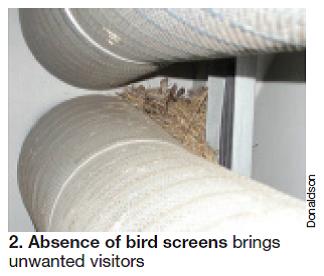
A weather hood is provided at the entrance to the air inlet structure for most gas turbines today. Its purpose is to protect filter elements from direct impingment by rain, snow, flying birds and insects, dirt, etc. Some are equipped with screens to prevent birds and large airborne debris (such as leaves, plastic bags, etc) from entering (Fig 2), moisture separators to remove large water droplets from the incoming air, and coalescing filters or drift eliminators to remove small moisture particles (such as fog).
Inspection goals are obvious: Check the condition of the rain hood and screens, moisture separators, etc, required for trouble-free operation. Also, the inlet heating system, if installed, to protect against icing and filter blinding in winter.
Air filtration
Condition assessment of the filtration system is considerably more involved and may require expert guidance if you’re doing it for the first time. It’s not very difficult to see a hole in a filter or other physical damage. Nor is it difficult to identify corrosion/rusting of metal components, which is of greatest importance if it occurs on the clean side of the media.
It’s also easy to identify fouled media. But the dirt you see might not be a bad thing and not a reason for replacement. Dirt is evidence that your filters are doing their job. In fact, fouled media has a higher filtration efficiency than new, so you probably don’t want to replace filters until the pressure drop across the filtration system is, say, 4 in. H2O—1.5 in. H2O for the prefilter if installed and 2.5 in. across the final filters. A delta p of 4 in. H2O translates to about a 1.4% loss in output and about half a percent loss in heat rate. Check the pressure drop before beginning your inspection: No sense spending time assessing filter condition if replacement is imminent.
But pressure drop doesn’t tell the whole story. Some filters—particularly those in peaking units—may show no visible signs of problems but should be replaced. Media degrades over time (it shouldn’t be mushy or brittle), faster in some areas than others because of ambient conditions and airborne contaminants. If your filters have been in service more than three years, it’s a good idea to remove a couple of elements and have their physical properties tested. You can have this done by an independent lab for a nominal fee or by the filter supplier.
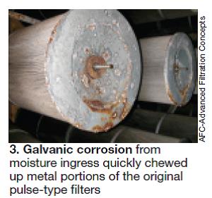
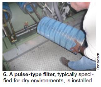
While you’re checking the filter media, inspect holding frames and grid plates, evaluate retaining hardware (Fig 3) and assure proper torque, check the quality of the seal between the filters and the holding frame (caulking might be necessary), and for pulse filters, verify that the filter tripods (yokes) are straight and in the right position (12, 4, and 8 o’clock). Note that yokes often are bent by installers who stand on them; continuous supervision of ongoing work is important.
Readers with self-cleaning filters may recall that the cylindrical and conical filter sections have neoprene gaskets to help prevent air bypass. In particular, ensure that the gasket between the final filter and tubesheet is airtight. Also important: Verify that solenoid valves, pulse cleaning controls, compressed air, and electrical systems are functioning properly.
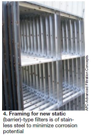
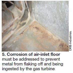
If you find rusted frames, you have two options: replace (Fig 4) or remove offending rust and apply a suitable coating. Regarding the latter, the method used to remove rust anywhere in the air inlet house is very important (Fig 5). Knowledgeable plant maintenance personnel warn against a grit blast because it is virtually impossible to remove all the foreign material before restarting the engine. Use a needle scaler instead.
Leakage paths for unfiltered ambient air to enter the compressor include (1) poor sealing between filters and support frames and between the frame structure and the walls, floor, and ceiling of the compartment, (2) holes in the compartment’s walls, floor, and ceiling, (4) access through compartment drains, (5) at joints in the ductwork, etc. They typically can be identified by standing inside the darkened air inlet house on a bright day and looking for sunlight. Another method is to pressure wash the ductwork from the outside and look for water ingress.An aggressive cleanup is critical to protect the turbine. Broom clean does not pass the cleanliness test. Vacuum brushes and complete wipe-down with lint-free rags before recoating are recommended. A premium two-part epoxy seems to be the preferred coating system.
That’s the easy part. An important part of the inspection process, particularly if you are new to the plant and are in a supervisory position, is to check the arrangement of the filtration system and verify its suitability based on current ambient conditions. To illustrate: Self-cleaning filters, although installed may not be appropriate for plant locations where the humidity is high.
Verify, too, that air velocity is uniform across the inlet duct and that the face velocity across the filter elements is within design limits. A couple of experts told the editors that they have encountered air inlet houses that are undersize for the service. The result: Velocities significantly above those recommended for the filters, evap media, and mist eliminators.
Telltale signs of high velocity include corrosion of silencers, streaking on side walls downstream of the mist eliminators, standing water, filters that have blown out, and compressor fouling caused by particulates in the air bypassing the filters.
Use an anemometer to check air velocity across the filter face. If the plant doesn’t have an anemometer, buy one; only costs about a grand. The OEM’s specification for your air inlet house should provide the design velocity for comparison purposes.
Where evap coolers are installed, Munters Corp, Ft Myers, Fla, the leading supplier of this equipment for GT applications, recommends a face velocity of 525 in the middle of the filter field, 650 ft/min at the corners. These numbers assume a drift eliminator is installed.
Don’t be surprised if you find velocities at the corners of the filter array and the evap-cooler media that are twice what you measure in the center. Re-engineering of the inlet structure may be necessary to correct the problem and properly protect the compressor both from water carryover and from corrosion products that spall off ductwork, filter supports, inlet silencers, etc.
If re-engineering is in your plant’s future and the air inlet structure must be rebuilt—it’s not a big deal, really—be sure to evaluate beforehand how the current materials of construction have performed. If you’re seeing corrosion, or peeling of galvanized coating, consider stainless steel for new construction—preferably Type 316L.
This also is a good time to review the plant’s experience in maintaining the air inlet system. Perhaps access to the filters can be improved with addition of more doors, permanent stairs and platforms, etc. Think about improving safety as well with handrails, guardrails, etc. Look back through the OEM’s advisories and technical information letters as well and implement those recommendations.
One inlet-cooling expert the editors spoke with suggested that users might want to consider eliminating inlet silencers if the plant is in a remote location and sound attenuation really is not necessary—especially so if a fogging system is installed. Reason: Silencers, or any other component in the air flow path downstream of fogging nozzles, promote droplet agglomeration. And that includes trash screens. All are a potential source of hard particles from corrosion and erosion processes.
Open discussions at the many GT user-group meetings often acknowledge compressor damage from water droplets and hard particles associated with having trash screens, but none, to the knowledge of the editors, identified the trash screen with preventing a catastrophic loss by stopping foreign material from entering the unit.
Hire a pro to do the design work for the re-engineering effort. And do some research on your own. Confer with colleagues at the next user-group meeting. Also troll the online discussion forums supported by the various user groups to identify a couple of plants that have recently done work like you are planning and connect by phone to learn more about what works, what doesn’t.
When new filters are necessary, resist the temptation to make a snap decision and simply replace “in kind.” Or purchase based on lowest first cost. In the three years or more that your filters have been in service there may have been changes in ambient air quality and operating schedule that could impact filter selection. Plus, offerings from the filter vendors have changed. For example, HEPA filters recently have emerged as a viable alternative where continuity of compressor cleanliness is a business advantage. It’s certainly worth starting with a clean sheet of paper and making a proper evaluation.
Who’s going to replace your filters (Fig 6): plant staff, filter supplier, contractor? This is a big job for a 7FA—450 pulse-type filters by one maintenance manager’s count (each consisting of a cylindrical and conical section)—especially the first time, when you have to figure out how best to accomplish the task.
Use of contractors sometimes draws a caution flag in industry discussions because of unsatisfactory experiences. Who can’t change filters? You don’t want to learn. So, unless you know the contractor or can validate its competency you might want to pass. The filter manufacturer is a safe choice as is your staff.
If plant personnel are available and you choose to handle the project in-house, here are a few questions to ask yourself:
- How will you get the new filters—they are not light—to where they’re needed? An extended-reach aerial platform is one idea.
- Do your old filters qualify for disposal in any landfill or must they be shipped to a special disposal facility? What tests are required for a disposal permit and what laboratories do this work?
- What are the paperwork requirements for transporting the old filters to a certified disposal facility? Insurance?
- How will you get the old filters into the disposal container without releasing fine dust, which might be considered a health hazard? An enclosed chute to a dumpster is said to work well.
Inlet cooling
Of the three inlet cooling options, evap coolers and foggers require particularly close inspection during a walkdown of the air inlet house. Where chillers are installed, there only are a few heat-exchange coils to look at.
Evap cooler. Inspection of the air side of an evaporative cooler is similar in some ways to that described earlier for air filters. For example, you want to verify there are no gaps between media segments that would allow air and water droplets to bypass the cooler. But here you also want to verify there is no water bypassing the media because that would reduce efficiency. Also, carefully check water flow rates and distribution. Dry streaks on the media are indicative of poor distribution.
Look at the walls of the air inlet house downstream of the drift eliminator. If you see streaking, something’s not right. Cause could be high air velocity, water bypassing the evap cooler, and/or a defective drift eliminator. Important to locate the source of the problem and correct it.
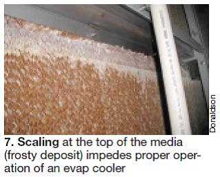
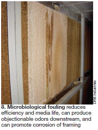
One expert quantified the impact of severe scaling this way: Blocks forming the top row of the media weighed in at 150 lb, or 30 times their original weight. Air velocity below the scaled media was in excess of 900 ft/min.Evap media should last three to five years (depending on conditions), according to the experts at Munters. It’s pretty difficult to miss scaling of the media (note the white scale at the top of the media in Fig 7) and fouling, such as that evident in Fig 8. When you see problems such as these, both of which adversely impact efficiency and reduce the effective lifetime of media, call the plant chemist. Tighter water chemistry should prevent further scaling; use of a proper biocide will eliminate microbiological activity. Sample water regularly—perhaps weekly—to assure system chemistry is within guidelines.
Other signs of media deterioration that demand your prompt attention include a “mushy” rating on the “feel” test and a delta p across the media that is double the as-installed pressure drop.
In addition, remember to do the following:
- Check framing, drift eliminator, sump, piping, pumps, and support systems for corrosion. Repair as necessary.
- Verify integrity of seals, gaskets, and caulking.
- Flush the sump and piping system thoroughly annually or more frequently.
- Send samples of the media and water to the evap-cooler supplier annually for evaluation.
Fogging system. If you have just taken a position at a plant with fogging system and you have no experience with this cooling technique, it’s important to verify, to the best of your ability, spray patterns and uniformity of flow among the various nozzles. It is considered good practice to send nozzles for flow testing annually, or every couple of years if they see relatively little service time.
Make sure the spray patterns do not directly impinge on the walls of air inlet house. This would cause the fine mist particles to agglomerate and possibly cause problems by slamming into compressor blades and vanes. Check, too, the material used to fabricate the ductwork. Galvanized steel can present problems because the high-purity water used for fogging is so aggressive that it can remove the zinc present and deposit it on inlet guide vanes and other compressor parts.
Having a window at the bellmouth for visual inspection of pooling or running water during operation is a good idea. If one is not installed consider it. Flowing water at the inlet can be avoided by setting the fog-system control parameter so the system always “under-fogs.” Translation: Maintain the air flowing into the compressor at slightly less than 100% saturation.
Finally, the fogging pump skid located outside of the air inlet house must be checked as well. Verify proper operation and seal integrity for the pumps, instrumentation, and other components in these very-high-pressure fluid systems.
Filtration
Static or pulse filter: What’s best for your plant? Have you ever considered HEPA?
Subscribers who began working at GT-based powerplants within the last 20 years may not be aware that many gas turbines installed in the 1960s and 1970s for peaking duty don’t have inlet filters. Most do have bird screens, however. These relatively low-power machines might run 50, 100, possibly 200 hr/yr to meet peak demand. So how much of a return, if any, could there be on an investment in air filters?
Readers responsible for such ageing infrastructure are lucky because deciding on what filters to buy for today’s high-efficiency GTs is a challenging task. Some reasons why maintenance managers get frustrated:
- Air-inlet filter standards do not focus on the specific needs of GT owner/operators. The same standards are applied equally across unrelated markets —such as HVAC, pharmaceutical clean rooms, and powerplants.
- There are European- and US-based standards organizations and they have different specifications.
- Some methods for measuring filter effectiveness—arrestance (or weight of captured particles), for example—are meaningless for fine-dust filters that do most of the work protecting against compressor fouling. The small particles of greatest importance do not weigh much, but they outnumber large particles by several orders of magnitude.
- Standards and test methods are continually evolving.
In addition, there are filter-media options to consider—synthetics versus cellulose, nanofibers versus microfibers, etc. The optimal selection for your plant depends on ambient conditions (table). For example, what works best in a dry or wet clime, near seacoast where salt is entrained in the air, near industry, in a pristine location?
As with everything you buy, be wary of the low-cost sales proposition. No one wants to spend more than necessary, but the purpose of the filters is to protect the most important piece of equipment in the plant. A simple cost/benefit analysis will prove that it’s worth paying a little more to assure high availability and a clean compressor to maximize performance.
Simplifying selection
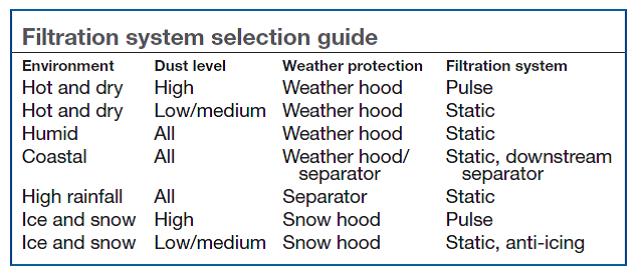 While it’s certainly worthwhile doing some background reading on filters, be prepared for an onslaught of material if you simply “Google” the subject. At the most basic level, filter choice comes down to either a static (barrier) or a pulse (self-cleaning) design. Pulse systems usually consist of some form of weather protection followed by a deep-pleated cylindrical and/or conical filter. The filters are cleaned periodically by means of a reverse pulse of air.
Static systems typically have weather protection as well, plus prefilters to remove coarse contaminants and high-efficiency filters to get the fine dust. There are many types of each to choose from. Because static filters do not self-clean like the pulse filter, when they reach a certain pressure drop replacement is necessary. Prefilters are changed more frequently than high-efficiency filters, which may last anywhere from 8000 to 24,000 hours depending on the environment, operating duty, etc.
Another option: Swap out the conventional fine-dust filter with a HEPA filter, or install a HEPA downstream of the fine-dust filter, if eliminating performance degradation and/or online and offline compressor washes are critical goals.
The standards recognized today for GT filter specifications are ASHRAE 52.2 and the European Committee for Standardization’s EN779. If you’re going the HEPA route, add EN1822 to the list.
ASHRAE filter designations are MERV (Minimum Efficiency Reporting Value) 1 to 16, which you’re probably familiar with. MERV 2 through 4 are specified most often for prefilters; MERV 13 through 16 for fine filters, with 14 and 15 most popular.
The equivalent filter designations for EN779 are G2-G4 for large particles and F7-F9 aligning with MERV 13 through 16.
HEPA designations H10, H11, and H12 associated with the limited number of powerplant applications to date are specified by EN1822, which was updated his year. The existing standard for fine filters, EN779, cannot classify HEPA filters because HEPA-filter performance exceeds the testing capability of the standard. Think of this as trying to measure 1 in. with an ungraduated 12-in. rule.
Both the ASHRAE MERV 1-4 and EN779 G1-G4 classification tests reflect the weight percent of standard synthetic dust particles in the size range of 3 to 10 microns removed by the filter without exceeding a specified pressure drop. Both the MERV 1 and G1 filters collect less than 65% of the particles by weight, MERV 2, 65% to 70%; MERV 3, 70% to 75%; and MERV 4, more than 75%. By contrast, the G2 range extends from 65% to 80%; G3 from 80% to 90%; G4 filters capture more than 90% of the particulates by weight.
For establishing fine-dust filter classifications, ASHRAE uses synthetic dust particles in the range of 0.3 to 1 micron with an average size of about 0.65 microns. However, the percentages here refer to the percentage of particles removed rather than the weight percent removed for MERV 1-4.
The ratings: MERV 13, fewer than 75% of the particles from 0.3 to 1 micron are removed; MERV 14, between 75% and 85%; MERV 15, between 85% and 95%, and MERV 16, more than 95%. MERV 13-15 also remove more than 90% of the particles in the inlet air between 1 and 10 microns; MERV 16 removes more than 95%.
The EN779 fine-dust classifications differ from ASHRAE in that the Europeans use a synthetic dust comprised of 0.4-micron particles—in effect a more demanding test than 52.2. An F7 filter captures between 80% and 90% of the particles, F8 between 90% and 95%, and F9 more than 95%.
While the ASHRAE and EN779 standards appear challenging at first glance because of the high percentages, keep in mind that any filter with a MERV rating could allow virtually all particles smaller than 0.3 micron to pass through and still meet the specification; for EN779 classifications, particles smaller than 0.4 don’t have to be removed from the air stream.
Perspective is important here: The normal particle distribution in a typical urban ambient air reveals that there are 100 times more 0.1-micron particles than 0.5-micron particles. This is why you can buy a top-of-the-line MERV 16 filter and still watch compressor performance drift downward until you wash online and/or offline.
The EN1822 standard for HEPA filter classification differs significantly from ASHRAE 52.2 and EN779. Note that there is no comparable US standard at the present time and there are only a few laboratories capable of measuring the very small test particles required for HEPA classification. Test equipment is quite expensive.
HEPA ratings as defined by EN1822 are based on the minimum capture rate of the most penetrating particle size (MPPS). In plain English, MPPS is the particle size that has the lowest capture efficiency for the media tested. The defining size usually is in the 0.05-0.2 micron range, which coincidentally is the range of particle sizes oft associated with compressor fouling issues.
So for a standard test using dust particles from 0.04 to 0.5 micron, you might capture 99.95% of 0.05-micron particles, 99.90% 0.07-micron particles, 99.85% of 0.15-micron particles, 99.5% of 0.13-micron particles, etc. In this case the MPPS would be 0.15 micron.
Rules of classification require that MPPS particle capture (in percentage of particles) must be at least 85% to be rated H10, 95% for H11, and 99.5% for H12. The 99.85% capture of MPPS 0.15-micron particles for the example described qualify the filter for H12 status.
Perhaps the most worthwhile and current reference on GT air inlet filters for powerplant personnel can be downloaded from the Gas Machinery Research Council website at www.gmrc.org. The 122-page “Guideline for Gas Turbine Inlet Air Filtration Systems,” prepared by Southwest Research Institute and published April 2010, is a comprehensive effort, both practical and scholarly, that offers something of value to everyone involved with gas turbines.
It begins with the consequences of poor inlet filtration; discusses all aspects of filter selection, including life-cycle cost analysis; operation and maintenance; and testing, which gives details on ASHRAE 52.2, EN779, and EN1822.
HEPA: an alternative to compressor washing
Relatively few US gas-turbine owner/operators were familiar with the use of HEPA filters for GT air-inlet applications before the V Users Group’s 2007 meeting in Glen Cove, NY. It was there that RWE npower’s John Macdonald explained to the industry how high-efficiency filters could eliminate the need for online and offline compressor washing. That sounded important to several owners of GE F-class turbines in the room who had been told washing could be an underlying cause of R0 blade failures.
One concern of attendees was the potential for high pressure drop across the filter bank and its associated cost. But the experienced Macdonald, who is based in the power producer’s UK central engineering offices, assured the group that the delta-p impact is not as great as most might think—at least based on his rigorous analyses.
While an H12 filter could increase the pressure drop across an existing inlet filtration system by 50%, he said, the degradation in power production is relatively constant over time and the plant would not get the “big hit” caused by fouling.
At the time, he and his colleagues were evaluating the addition of a HEPA stage to the filtration systems for Didcot B’s gas turbines. They were encouraged by the favorable experience with HEPAs at ScottishPower’s Damhead Creek Power Station in southern England, and International Power’s Saltend Power Station, near Hull in the northeastern part of the country. Neither plant was washing online or offline.
Macdonald described the arrangement of air filters for RWE npower’s Didcot B, which consists of two 2 × 1 combined cycles capable of producing up to 1360 MW. The facility is located alongside Didcot A, a 2000-MW coal-fired station. The inlet air houses for the Didcot B GTs have rain hoods, followed by coalescers, and two filtration stages (prefilter and F8 final filter). Coalescers were washed periodically; life of the final filters was about two years. Using this filter lineup, compressors were online washed approximately weekly and offline washed periodically.
The alternative considered by RWE: Retain the coalescer, prefilter, and swap out the F8 filter with an H10. This project was completed only recently, Macdonald told the editors in mid August, so no operating data are available yet. If expectations are met, the H10s could be replaced with H11s or H12s when they reach end of life.
A similar retrofit project is being evaluated at Little Barford Station 2. That site has two GE 9Fs with two-stage static filters, one operating with F9 final filters and the other with H10s. Despite the relatively short operating period for comparison purposes, performance of the H10 has been measurably better.
Compelling evidence that RWE npower views HEPA filters favorably: Combined-cycle units under construction at Staythorpe in Nottinghamshire and at Pembroke in West Wales are equipped with H12s. The first of four Alstom GT26B-powered, 425-MW, 1 × 1 combined cycles at Staythorpe began acceptance tests in August. Plans are for the entire station, located on a compact brownfield site and former location of two coal-fired units, to be operational by year-end.
The five Alstom GT26-powered, 400-MW, 1 × 1 combined cycles at Pembroke are scheduled for operation in 2012. This site previously supported an oil-fired station since decommissioned.
A little digging revealed that HEPA filters had been installed on several aero GTs—both onshore and offshore—years before they were adopted by the large frame engines. American Air Filter International, Louisville, told the editors about land-based GE aeros being equipped with their HEPA filters as far back as May 1992; an offshore Frame 5 was so equipped in 1981.
Mitsubishi experience. Interestingly, AAF is part of a Japanese consortium that considers itself the world’s leading provider of air filters. This connection undoubtedly has facilitated a relationship with Mitsubishi Power Systems. Several M501F, M701F, and M501G machines have been installed in Bangladesh, Hong Kong, Spain, Taiwan, and Mexico with HEPA filters.
A top-level Mitsubishi manager told the editors, “We encourage our clients to use HEPA filters. We have impressive examples in Mexico where one client has them and another next door (exactly the same configuration) doesn’t. Comparisons of compressor fouling and performance deterioration are simply amazing.”
HEPA filters reduce or eliminate the need for online and offline washing, he continued; however, this is an economic decision for the customer to make.
Mitsubishi offers a three-stage system which makes use of the existing prefilter and standard filter and adds a third HEPA stage. But considerable effort is required to do this. For example, the air inlet house has to be made larger and structural steel must be reinforced. To avoid major modifications, the company developed an upgraded HEPA filter that can be retrofitted into the filter housing designed for two-stage systems. Typical replacement interval for both systems is one year. Both are designed to remove 99.97% of the particles 0.3 microns and larger.
Careful monitoring both of a turbine outfitted with the upgraded HEPA filter, and a sister unit at the site using conventional filters, revealed an average improvement in output of the HEPA-equipped combined cycle of 1.7% over the two-year study period; average plant efficiency improvement was 1%.
Translating this to dollars for a M501G-powered 1 × 1 combined cycle operating 6000 hr/yr, Mitsubishi engineers came up with an annual increase in net operating revenue of $1.6 million and a $250,000 annual penalty for the higher-cost HEPA filters. Net gain: $1.35 million. The OEM’s numbers assume HEPA filters are four times as expensive as conventional filters.
Gore. About 10 manufacturers are actively pursuing GT owner/operators for their replacement filter business. But only W L Gore & Associates Inc, Elkton, Md, seems focused on HEPA filters at present. Perhaps the others believe the cost hurdle is too difficult to overcome: Turbine air filters often are considered a commodity with price the deciding factor in the selection process.
Gore says it has the best HEPA technology. “Field experience with advanced membrane-based HEPA filtration,” a paper by the company’s Marc Schroeter and E.ON UK’s Peter Hall presented at Power-Gen Europe 2010 last June, reports Gore’s filter media offers a significantly lower pressure drop and longer effective lifetime than competitors’ products.
The company’s three-layer HEPA filters feature an expanded polytetrafluoroethylene (ePTFE) membrane for removing very small particles, water, and dissolved salt crystals.
Referring to Fig 9, note that the prefilter layer removes most of the coarse and submicron particles and retains them with a minor pressure-drop penalty. Depth filtration assures long filter lifetime.
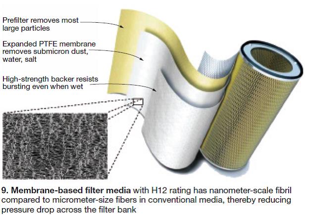
Finally, a high-strength backer provides high burst strength even when wet. Wet burst tests of cartridge and panel filter elements containing this media exhibited burst pressures upwards of 30 in. H2O. The combination of the three layers is pleated and integrated into standard cartridge or panel designs for installation in most existing filter houses without difficulty, according to the presenters.The ePTFE membrane reportedly provides an extraordinarily large surface area and is not susceptible to water ingress. The authors said its nanometer-scale fibrils and nodes minimize pressure drop because of “slip flow.” Here’s how they explain the phenomenon: The drag force on a nanometer-scale fibril is smaller than that for micrometer-size fibers used in other HEPA designs and the molecular movement of the air molecules contributes to the overall air flow, thereby reducing resistance.
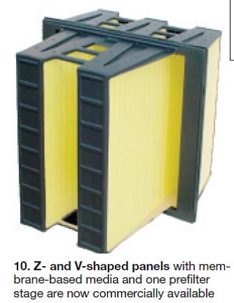
Gore recently announced a new Z-panel design (Fig 10) that the presenters said had half the pressure drop compared to an H12 V-shaped panel with microfiber glass media. Another benefit of the Z- or V-shape panels with membrane-based media now commercially available: Only one prefilter stage—either G4 or F5 (EN 779 class)—is required so no structural mods of the air inlet house are necessary.
The filter manufacturer first began testing its membrane-based media nearly six years ago in Europe. All sites reported the elimination of compressor fouling as well as a filter lifetime similar to the F8 or F9 cartridges used previously.
Site 1, an industrial plant on the West Coast of England operating a 31-MW Rolls-Royce RB211. Single-stage filter house had 112 pairs of F9 conical/cylindrical cartridges. Plant operator E.ON UK was experiencing power loss up to 3 MW before offline washing every other month.
Results with Gore filters installed in March 2008 with an additional prefilter wrap: No drop in output was reported, no compressor washing was necessary. Filters were replaced after 7600 hours, comparable to the F9s which averaged 7550 hours.
Site 2, an industrial site in Spain about a mile and a half from the Mediterranean Sea operating a GE 9FA. Air inlet house had 700 F9 conical/cylindrical cartridges; corrosion and compressor fouling were issues. Since installation late in 2009, the Gore HEPAs have met expectations (no decrease in expected power output, no significant increase in pressure drop across the filter stage).
Site 3, at a desert location in the Middle East offers insight into pressure drop through HEPA H12 cartridge pairs serving a 7.9-MW Siemens SGT-300 (formerly known as the Alstom Tempest). These filters are continuously pulse-cleaned—every 20 seconds two cartridge pairs are hit with 100-psig compressed air to release collected coarse particles. Delta p through the filters after seven months of operation still was an acceptable 0.96 in. H2O (260 Pa); performance degradation was nil.
Site 4, an industrial site with a GE Frame 6B offers early data on the performance of the Gore Z-panel filter element shown in Fig 10. With G4 prefilters and an F8 stage clipped on to the final H10 filter, operators were online washing monthly, offline quarterly.
Last fall, the 120 panels were swapped out with 78 Z and 42 V panels with the membrane-based media; 66 G4 bags were again selected for the prefilter. Note that space restrictions in the filter house militated against using Z panels throughout. Results for the first four months: pressure drop through the prefilter, same as before; delta p through the final filter stage, 1.4 in. H2O (350 Pa); no compressor efficiency loss; no decline in power output. Update: After 10 months of operation, the final-filter differential pressure is about 2.4 in. H2O (600 Pa).
Site 5, TransCanada Corp’s Grandview Power Plant, New Brunswick, Canada. Plant Manager Rick MacDonald told the editors his facility has two LM6000PDs (COD December 2004) running base load (8400 hr/yr) in cogeneration service on pipeline gas. Grandview is located at sea level, less than a mile from the ocean, adjacent to a refinery, and in close proximity to other industry. Think for a moment about what witch’s brew of contaminants could be entering the air inlets of those GTs.
Gore HEPA filters were installed in Unit 2 two years ago because of performance issues that required a shutdown about every six weeks for an offline wash to recoup the 1 to 2 MW lost because of a dirty compressor. HEPA results impressive over the next year. The upgraded engine was washed every four months when
mandatory borescope inspections were conducted—simply because it was convenient to do so.
MacDonald said there had been no significant performance degradation; likewise, after the washing there was no uptick in output. The plant manager added that he believed the GTs could go six months or longer between offline washes.
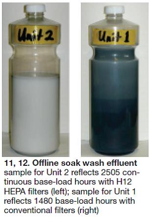
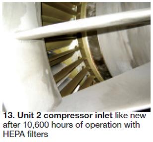
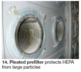
Standard filters on Unit 1 were replaced with HEPAs in October 2009 and the generator cooling-air filters were changed out as well. Fig 14 shows the pleated prefilter insert used to protect the HEPA cartridges from large particulates. MacDonald thinks he’ll probably get three years of service from the Gore filters, which is what he was getting with the original product.Proof was offered by sampling the washing solutions from both engines. Fig 11 shows the milky white sample (with a hint of gray) from the HEPA-equipped engine, Fig 12 the black sample reflecting deposits removed from the compressor of the engine with the standard filter. Fig 13 shows the Unit 2 compressor inlet after 10,600 hours of operation.
MacDonald ran through the economics that justify HEPAs for his engines. As a starting point, he assumed that HEPAs cost five times that of a leading conventional filter. Taking credit for the water and soap saved, plus the disposal cost of the spent washwater solution, MacDonald said HEPAs cost four times more than conventional filters.
For Grandview, which has a tolling arrangement, the ability to maintain clean-engine performance means the plant can produce and sell more power throughout the year. The additional revenue, plus eliminating the expense of shutting down every six weeks, more than offsets the nominal $1000 per month more the plant pays for the HEPAs over a three-year cycle.
MacDonald stressed that the economic analysis for virtually every situation will have a different result. It depends primarily on how a plant is paid for services rendered. The facilities benefiting most probably are those able to bid a higher capacity into the ancillary services market.