


Lea Power Partners LLC
Western Generation Partners
Operated by Consolidated Asset Management Services
604-MW, gas-fired, 2 × 1 combined cycle located in Hobbs, NM
Plant manager: Roger Schnabel
Duplex lube-oil filter installed on BFP-skid fluid drive
Challenge. Under the original design, debris from any failed bearing in the system would be collected in the fluid-drive sump and then circulated through the system. This would cause damage to other bearings. Of particular concern was the debris that would accumulate inside the dead zones of the shell-and-tube lube-oil coolers. The design of those heat exchangers made them difficult to clean after a bearing failure. Debris hidden in the coolers would circulate onto the new bearings and cause premature failures.
Solution. Adding a set of duplex filters after the pumps and before the lube-oil coolers eliminated recirculation of bearing debris through the system (Fig 1).
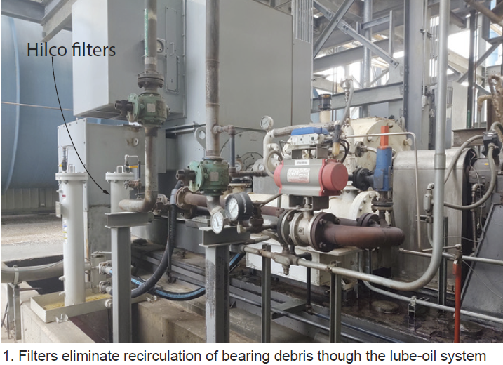
Results. After an upcoming overhaul, the heat exchangers will be cleaned thoroughly. They will remain clean because lube oil now is filtered. Even if a bearing failure were to occur, debris from that failure would be removed by the filters and not get into the lube-oil coolers. This will increase fluid-drive reliability and increase bearing life.
Duct-burner fuel-skid shut-off valve leakage test retrofit
Challenge. The duct-burner control system wasn’t designed to allow operators to leak-test valves in the fuel-gas system. The leak test is an insurance-company requirement.
Solution was to add a block valve between the last block valve and the duct-burner distribution manifolds, plus a bleed valve, vented to a safe location between the two block valves (Fig 2).
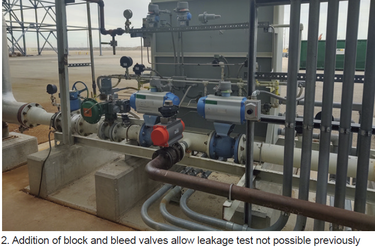
Results. The system now can be isolated from the duct-burner manifolds and tested for leaks. A leak test was performed during a recent outage and satisfied insurance-company requirements.
Redundant filter system for ammonia injection skid
Challenge. The original design had a filter before the single valve controlling ammonia flow to the HRSG. Debris from the ammonia tank would collect in the tubing and plug the filter. An outage was required to correct this problem each time the filters clogged up.
Solution was to add a second filter in parallel to the original one with all the required block valves, drain valves, and pressure differential gages, thereby enabling one line to be taken out of service without stopping ammonia flow to the HRSG (Fig 3).
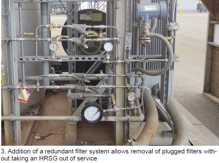
Results. After this modification was completed, the second filter was placed in service and blocked off. Once the filter in service shows sufficient pressure differential, the standby filter is lined up. Thus, a filter can be changed-out without taking an HRSG out of service.
Featured Solutions Provider

Redesign HRH bypass steam diffuser in the ACC duct
Challenge. The hot-reheat bypass diffusers in the air-cooled-condenser duct were failing regularly. The diffusers were fabricated of ½-in. plate in two sections with ½-in. holes totaling 50-in.² of flow area. The holes were very close together (Fig 4) and a combination of flow and vibration would break the metal between the holes. In the first 10 years of plant operation these diffusers had failed twice.
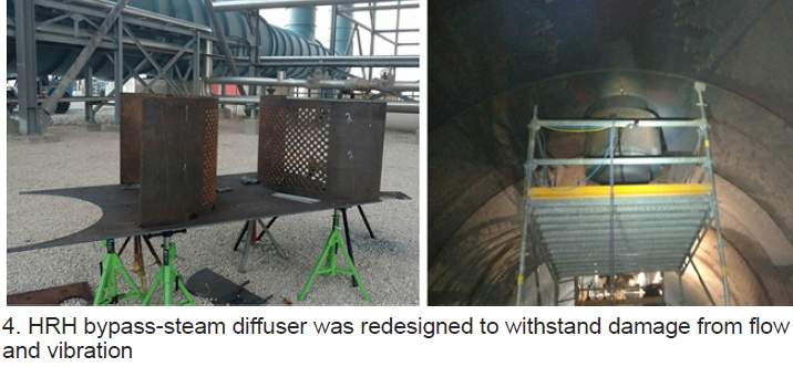
Solution. The solution was to redesign the diffuser area, using the same ½-in. plate but drilling 1-in. holes on 2-in. centers for the same total flow area. This increased the distance between holes and therefore making the entire diffuser much stronger to withstand the flow and vibration.
 Results. Following the installation of the newly designed diffusers, the ACC duct was inspected after about four months of operation. The diffusers showed no damage or cracks. Plant personnel plan to monitor diffuser condition whenever the opportunity exists.
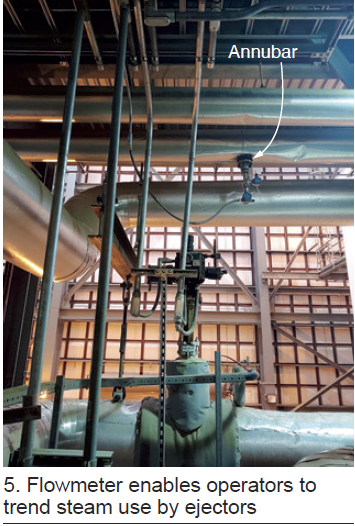
Flowmeter installation on the air-ejector steam line
Challenge. As designed, the plant didn’t have a flowmeter to measure the amount of steam used by the ACC air ejectors. This made it difficult to evaluate ejector performance.
Solution was to install an annubar in the steam line common to all the ejectors (Fig 5).
Results. After flowmeter installation, the plant was able to trend steam use by the ejectors during startups and normal operation. Flow measurement has helped in the troubleshooting of ejector issues that could not have been diagnosed previously.
Upgrade heat-trace control panels to alert CRO with DCS alarm
Challenge. Heat-trace control panels (HTCP) supplied with the plant included individual breaker-condition indicator lights on the front of the panel for local indication of a problem. During cold-weather operation, plant operators were making frequent rounds to verify there were no tripped breakers on the HTCPs that could lead to plant reliability issues caused by frozen instrument sensing lines.
Solution. Install new cable runs from HTCPs to the control room DCS. Wire the relay board to create an alarm series circuit such that if any breaker trips an alarm is generated on the DCS. In addition, create new alarm points and graphics screen on the DCS (Fig 6).
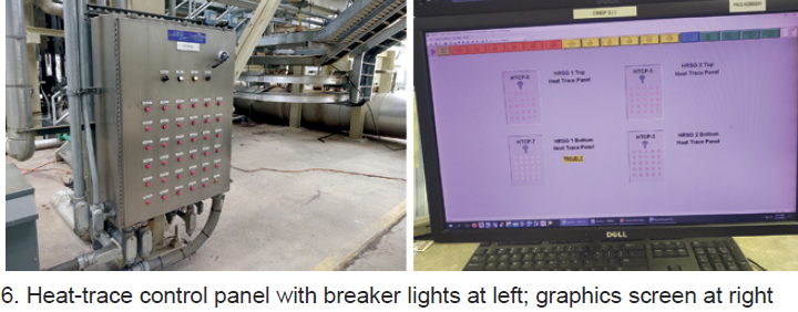
Results. After the HTCP remote alarms were implemented, the incident rate of frozen transmitter sensing lines was reduced by early detection which allowed faster corrective action. The HTCP DCS alarm functionality has improved overall facility cold-weather reliability.
Project participants: Roger Schnabel, Carlos Sanchez, Richard Shaw, Kelvin Mendenhall, and Tyler McCoy