


By Steven C Stultz, Consulting Editor
The HRSG Forum with Bob Anderson contributes significantly to industry knowledge on the design, operation, and maintenance of heat-recovery steam generators with its lineup of technical presentations by subject matter experts, plus hands-on discussions among owner/operators, component and service providers, and concerned OEMs. In sum, this premier event encourages the exchange of experience and specifics that keep the industry as dynamic as its markets.
“Dynamic” continues to be a dominant description and theme of the HRSG Forum. The fourth annual conference in 2019 showed a growth in registrations and in percentage of equipment users, and in relevance. The agenda was informative, meaningful, and well organized.
This year’s sponsors included Dekomte, Precision Iceblast, Vogt Power, Taylor Industrial Coatings, Nooter/Eriksen, Zepco, Questec Solutions, HP Valves, Environmental Alternatives, and Copes Vulcan.
A review of the 2019 event, held July 23-24, in Orlando, follows.
Duke Energy’s experience in preparing its HRSGs for cycling
“Controlling condensation is a major HRSG team focus,” explained Eugene Eagle, Duke Energy. “Our long-term goal is asset protection and reliability.” The company’s lead HRSG engineer addressed participants on Duke’s extensive experience with HRSGs in North and South Carolina, explaining how it is preparing HRSGs for cycling.
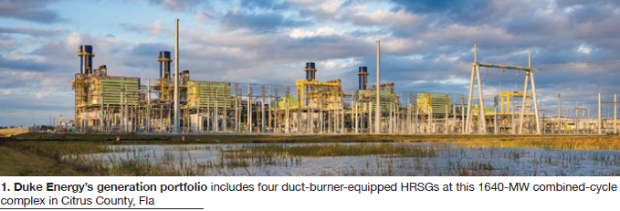
All Duke HRSGs are triple pressure with reheat, equipped for duct firing, and originally designed for baseload and load-following. Most are within 2 × 1 F-class 500- to 800-MW combined-cycle configurations (Fig 1).
His emphasis was damage prevention: “We manage equipment. It does not manage us.” In other words, the hardware is there. You just need to use and care for it properly. This focus aligned with a principal theme of every HRSG Forum: long-term system reliability.
Eagle also offered detailed market backgrounder on the increasing need for cycling. Renewable energy continues to enjoy first-dispatch status, he said. Eagle’s analysis highlighted solar power, now targeting 2500 MW at Duke Energy alone. A solar-project status report for the continental US showed 35 GW in operation and another 75 GW under construction.
His summary: “On/off cycling, low loads in spring and fall, and flexible operations will become more common” as we are forced to defer to renewables. That means Duke must learn how to operate their combined cycles in cyclic mode while dramatically reducing thermal/mechanical fatigue damage to their components and systems.
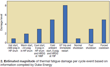
A summary chart on expected unit life brought clarity, comparing damage levels for the most common cyclic events (Fig 2). “Units designed for baseload service will need to be modified,” he stated, “especially for condensate removal. Proper attemperator operation is also critical.”
Condensation can cause thermal-transient fatigue damage, as mentioned several times during the Forum and in detail in “Trends in HRSG reliability, a 10-year review,” published recently in CCJ ONsite.
Eagle’s focus areas addressed common Forum participant concerns:
- Superheater and reheater drains.
- Attemperators.
- Startup and shutdown procedures.
- Heat conservation after shutdown.
- Proper chemistry practice.
He noted that the HRSG team at Duke makes extensive use of EPRI reports and research, including both #1015464 (startup and shutdown) and #1018003 (thermal transients).
The challenges. Maintaining hot startup conditions with HP drum pressure over 500 psig is difficult for many reasons—including auxiliary steam needs, drain operations, pre-start purge requirements, and leaking valves. “About six hours,” he said, “is the limit” for a hot restart.
Efforts are underway at several Duke sites to install thermocouples on select high-pressure superheater (HPSH) and reheater (RH) tubes to help evaluate drain system performance, calculate potential tube damage from condensate, and provide input for component life-assessment reviews.
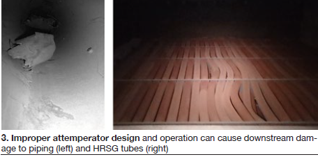
He then displayed severe attemperator damage (Fig 3) and offered some experience-based recommendations:
1. Avoid reducing HPSH/RH attemperator setpoints below 1050F. “It is better to overshoot on steam temperatures than to overspray to saturation.”
2. Never place the HPSH/RH attemperator temperature control valve (TCV) into manual control or reduce temperature setpoints. This will cause overspray conditions and significant pressure-part damage.
3. Upgrade attemperator block valves to metal-seated ball valves (bi-directional seats).
4. Use a TCV martyr/block valve master arrangement.
Best practices. During startups and shutdowns, two parameters should be independently controlled: HP drum saturation temperature (HP drum pressure) and HP/hot-reheat (HRH) steam ramp rates.
For startups:
1. Procedures should be divided into hot, warm, and cold using different ramp rates and recommendations for each.
2. Use heat soaks at periods of high stress to minimize thermal fatigue damage.
3. Maintain HP steam and drum ramp rates within limits.
4. Immediately after synchronizing the GT generator, select both the megawatt output and the GT exhaust gas temperature (EGT) to the minimum values to reduce heat input to the HRSG during subsequent HRSG heat-soak stages.
For hot shutdown:
1. If GE 7FA or 9FA, always use exhaust temperature matching (ETM) for every startup and shutdown.
2. If GE 7FA or 9FA, rapid ramp through the hot zone at the low-load isotherm.
3. Steam-cool the HP superheaters within about 50 deg F of saturation.
4. After transfer to bypass valves, build HP drum pressure back to 1600-1800 psig with bypass valves. This will ensure that HP drum pressure will be above 500 psig (hot-start criterion) following a 6-hr shutdown.
5. For Siemens units, Duke is still working through reducing EGT for minimum loads.
6. Complete a final stabilization of approximately 5 min at GT minimum load before cease fire.
This led to Duke’s plans for retaining heat in the system during shutdown. The company’s program includes the following actions and recommendations:
- Stack dampers are being added to some units.
- For units with installed bypass dampers, close the dampers immediately after the GT has ceased firing to keep cool air off HRSG tubes during coastdown at low load (about 5 MW).
- For units with installed stack dampers, close the dampers and isolate all steam, feed, vents, drains, blowdowns, etc, to retain heat and pressure.
- Avoid topping off drums during layup; top off only just before restart.
Eagle concluded with some broad-spectrum recommendations going forward:
- Review life assessment data.
- Continue to monitor cycling evolutions and make improvements to both operational practices and control logics.
- Install HPSH and RH tube-skin thermocouples; gather data to help refine drain operations and look for thermal damage mechanisms.
- Continue with cycling improvement projects, namely:
-
- Drain system upgrades.
- Stack dampers.
- Stack insulation.
- GT purge credits (with low condensate generation).
Participant questions and discussions covered potential benefits of additional automation (less operator input to attemperator spray), proper insulation and thermal seals, stack damper and stack insulation benefits, the possibility of electric-blanket heating for drums, attemperator inspection intervals, header and tube repair techniques (and preferences), and the benefits of complete root-cause analysis (RCA) for damage.
What ASME’s new rules for Grade 91 mean to operators
ASME recently reduced the allowable stress values for Grade 91 (Gr 91) steel, a topic anticipated and discussed at length in the previous HRSG Forums. “It was not a decision taken lightly,” explained Jeff Henry of Applied Thermal Coatings—Combustion Engineering Solutions (ATC-CES), Chattanooga, Tenn. Henry currently chairs ASME’s Working Group on Creep Strength-Enhanced Ferritic (CSEF) Steels (Fig 4).
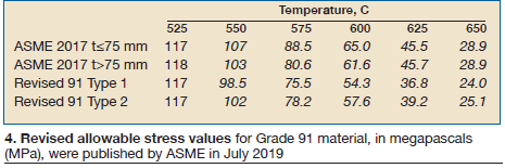
When reviewing the table, keep the following points in mind:
- The distinction made between tube wall thicknesses in the 2017 Code no longer is viewed as meaningful.
- Type 2 Grade 91 material has tighter restrictions on certain residual elements—such as copper, arsenic, tin, etc—than Type 1 material. The “cleaner” Type 2 offers better rupture ductility.
- Data presented in Roman type are governed by tensile or yield strength; that in italics by creep strength.
The primary industry and Forum participant concern: “What does this mean for owner/operators?” There is confusion at the plant level in the US regarding the impact on future operation of plants with Gr91 pressure parts, and there is concern about the higher cost of Gr91 Type 2.
In China, explained Henry, there is “both anger and confusion” over ASME’s action. In Europe, there is “a more muted response” because similar actions have already been taken there.
CSEF steels are metallurgically complex alloys that achieve improved elevated temperature strength through controlled chemical composition and heat treatment. However, the quasi-stabilized structure produced in the CSEF steel during successful processing slowly breaks down under the influence of stress at elevated temperatures.
At last year’s meeting, Henry focused on Gr91’s history and development, and the original allowable stress rating process that lacked long-term testing and used only a limited number of heats. This year he explained in detail the critical and complex stages of adopting any new code material, using Grade 93 and Grade 23 (and others) as examples.
“In determining allowable stresses,” he explained, “the ASME Boiler & Pressure Vessel Code (Code) process reviews tensile, creep, and stress-rupture property data obtained over the temperature range of usage, and applies specific criteria listed in Section III, Part D, of the Code. If alloy properties, and particularly the allowable stress values, are attractive to designers,” he continued, “the alloy will be specified for use in new construction and for replacements.”
During the process of adopting a new Code material, Henry explained, the original producer generates technical requirements for the alloy to be included in a material specification, adopted by a Standards-making organization like ASTM. This provides requirements including chemical composition, heat treatment, and mechanical properties that any producer can use to make the alloy (as restricted by any patents).
“But,” he cautioned, “other producers can offer their versions of the alloy if any patent restrictions can be skirted. The final product will not necessarily be in accordance with the original producer’s best practice, and new producers often focus on meeting minimum requirements of the material specification.” This could include the most cost-effective heat treatment cycle or production process (continuous cast versus ingot).
And one wake-up call: “To date, failures in Gr91 components seldom have occurred in base metal. Most failures have occurred at welds, where weld-related changes in structure govern life of the pressure part” not factored into the stress values. Also, current inspection techniques may not provide early warning of concerns.
So what does this mean for HRSGs?
1. For the existing fleet, the reduction does not mean the equipment is suddenly at risk.
2. If material problems exist or emerge, they are likely attributed to poor design, poor control of operating conditions, or poor quality control during either manufacture or installation (or both).
3. Assessments should be carried out to determine the significance of the Code reduction (if any) for individual components.
4. The main concern becomes margin, not necessarily material risk.
Henry then walked participants through typical staged assessment of plant conditions.Most concerning was a discussion on “implications for operators.”
“For new HRSGs and piping systems,” he predicted, “designers will look to stronger CSEF grades, particularly Grade 92 or Grade 93 (not necessarily a good outcome).” However, there is limited operating experience with Grade 92, questions remain over the poor damage tolerance of Grade 92, and there is less experience with Grade 93, even in Japan.
“Coupled with increasingly demanding operating conditions in response to expanding deployment of renewables,” he continued, “operators will likely face very difficult challenges in the coming years at a time when the resources available to successfully handle those challenges are more limited than at any time in the industry’s history.”
He repeated that we now have the loss of OEM metallurgy expertise, which is a “game changer,” along with elimination of support engineering functions within the utilities and operators. For the OEMs, he explained, this added expense was (in the past) in their own best interest as they “stood behind their designs and products.”
Unfortunately, he added, there are some smaller engineering firms that, although good, might not know how to address complex material interactions. “They might not know what they don’t know.”
Even more troubling was one participant’s prediction: “New builds are projected by some to be run by drones, not people.”
The reduced allowable stress values were released in July 2019 and are required by year end.
In this editor’s view, Jeff Henry’s presentations and discussions are timely, thought provoking, profound, and acutely informative. The HRSG Forum with Bob Anderson has become a prime venue for important updates to this critical issue. Henry is expected to return to the Forum in 2020 with additional updates and critical
Oxide growth and exfoliation 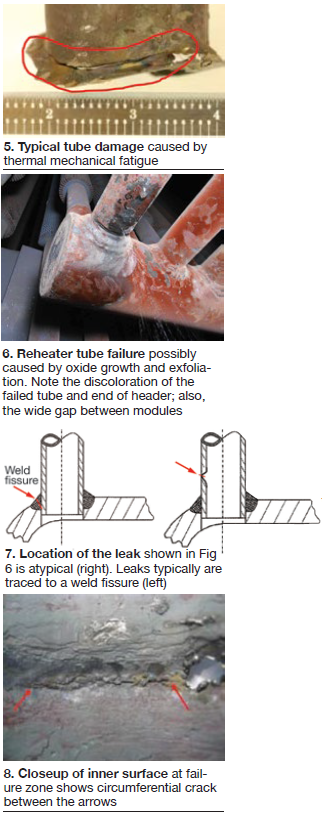
Barry Dooley, Structural Integrity Associates Inc, covered the important fundamentals of flow-accelerated corrosion (FAC), optimum cycle chemistry, repeat cycle chemistry situations, and the potential for film-forming substances. He then focused on oxide growth mechanisms in power generation cycles, specifically oxide growth and exfoliation (OGE).
“The morphologies of OGE are well understood for both ferritic and austenitic alloys,” he explained, considering superheated steam with temperatures up to more than 1100F.
OGE has become, he said, a major problem worldwide. “Steam growth oxides are semiconductors and grow by counter flux ionic diffusion processes of Fe2+ moving outwards and O2- (oxide ion) moving inwards,” he explained. Growth and exfoliation of oxides in steam do not depend on oxygen levels, but on the partial pressure of oxygen and other factors.
Anderson and Dooley then presented data and experience discussed recently at the European HRSG Forum about reheater tube failures apparently influenced by internal oxide growth and exfoliation. The referenced plant is an 800-MW 2 × 1 IPP near Bilbao, Spain, that began commercial operation in 2003.
This installation includes horizontal triple-pressure HRSGs behind 9FA+e gas turbines upgraded to DLN2.6 in 2015.
Since 2011, the plant has been moving toward more frequent starts and fewer operating hours per cycle. Currently, unit operations rotate with one unit down for a week.
Thermal mechanical fatigue was causing recurring leaks in the No. 2 reheater. Typical tube leaks caused by thermal fatigue are shown in Fig 5.
In the case presented, however, a reheater tube failure occurred on the tube side of the tube-to-header weld (Figs 6 and 7). The possible cause investigated was oxide growth and exfoliation.
RCA sampling showed an ID surface gouge where oxide was spalling off. See the circumferential crack in Fig 8.
No baffles exist between modules in this HRSG and tubes next to the gaps had operated at higher temperatures than those in the middle of the module. Partial tube blockage with exfoliated oxide was the apparent cause.
As Anderson explained, even a 3- to 4-deg-F temperature increase can accelerate oxide growth significantly. If the tube at the gap is running hotter than its neighbors, this could mean thicker internal oxide which would further increase tube metal temperature. Any resultant tube flexing could cause the spalling.
This analysis continues, and thermocouples are being added to tubes at the gaps at the side wall, at the module ends, and well away from the gaps.
Questions regarding this ongoing investigation included ability to determine remaining life of a reheater using oxide scale as an indicator. Another posed question: How do you know whether the issue is temperature rather than geometry? The answer: This particular case is showing a natural progression of a T22 tube impacted by increased temperature.
Assessment of pressure-wave cleaning technology for HRSGs
HRSG tube cleaning experience is typically included in the Forum, and the past few years have predicted increased consideration of pressure-wave tube cleaning technology. In 2019, this was the focus of a presentation by EPRI’s Stan Rosinski.
He addressed the primary concern of owner/operators—potential tube and structural damage.
Pressure-wave cleaning technology, using methane and O2, was first applied to HRSGs in Ireland in 2015 based on improved cleaning effectiveness, reduced outage time, and reduced labor. The principal provider is Switzerland’s Bang & Clean Technology AG. GE currently holds the US license.
To evaluate potential tube damage, EPRI conducted tests at the Colorado School of Mines Explosive Research Laboratory, and results were reviewed at the Forum. Experiments measured blast parameters of both single- and double-bag configurations to understand the performance and effectiveness of the process (including shock-wave physics on finned tubes). High-speed photography captured the processes.
Metallographic analysis showed no internal or external tube cracking, and no fin damage. Tubes are now at EPRI for further analysis.
The final technical report is under review. Anticipated long-term applications also include evaluation of damage to catalysts and air heaters.
Expansion joints and penetration seals
Jake Waterhouse, Dekomte, explained that most expansion-joint problems are with the casings, not with the seals. And he asked some key questions:
- Are the number of cycles specified when purchasing expansion joints?
- Are irregular stresses and movements being properly evaluated?
- What changes have been made since installation (patches, improvements, redesigns)?
He stressed that a key to reliability is technical assessment of current conditions and expected operations. He cautioned that “many HRSG OEMs can get it wrong in the original delivered design.”
Both visual and thermographic inspections become critical, creating condition reports that clearly state:
- Evaluation of fixing system and gas tightness.
- Review of adjacent elements for corrosion, cracking, or distortion.
- Internal review of expansion joints, including the flow plates and lining systems.
As combined-cycle plants face greater challenges, owner/operators must be aware of any duct fatigue during thermal transients, irregular stresses caused by movements, and any acid or water dew-point condensation.
The discussion then focused on penetration seals, and the differences between common OEM supply and retrofit options. Metal bellows seem to be favored by OEMs, Waterhouse suggested, but are often not flexible enough for long-term plant operations. Metal in-kind retrofits often must be delivered in split halves, or pipes must be cut and welded. Fabric retrofits, however, offer greater flexibility in the most compact design, and are favorable for high-movement areas.
Various applications were discussed, with examples, covering metal bellows, sidewall installations for hot and cold reheat, metal-to-fabric retrofits, labyrinth/gland seal-to-fabric retrofits, and limited access roof seals.
Availability and application of online pumpable (liquified) insulation also was discussed.
Questions and discussions included the pros and cons of insulation inside metal bellows.
Impact of water ingress into insulation
Anthony Cosenze offered Aspen Aerogels’ inaugural presentation at the Forum, focusing on how water reacts within HRSG insulation systems potentially leading to corrosion under insulation (CUI).
“Aspen Aerogels has been protecting insulated pipes and materials in the petrochemical industry for more than a decade,” he stated. Cosenze explained water’s behavior within insulation as a “BTU conveyor belt,” a process of wicking, evaporation, capillary action transport (vapor), and re-condensation (Fig 9).
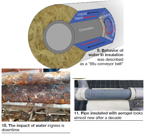
He followed with a case study from a US combined cycle involving a pinhole leak and ingress through a penetration seal with mineral-wool insulation. He likened the result to “a wet sock.” The insulation was removed, revealing significant OD corrosion (Fig 10). Next, Cosenze showed a photo of a pipe insulated with Aerogel after 10 years of operation (Fig 11).
HRSG examples discussed included penetration seals, HRH line bottom seals, and floor seal/boiler casing insulation integration systems.
A strong feature is reduced thickness and weight. Cosenze explained that a 2.8 in. thickness of aerogel/Pyrogel® offers the same insulating capability as 7 in. of calcium silicate or mineral wool, and is more hydrophobic (organic silicone base). Aerogel is lighter in weight (insulated pipe weight) with less wind loading, and is reusable.
Real-time health tracking of HRSGs and piping
Structural Integrity’s (SI) Ian Perrin discussed real-time health and damage tracking of HRSGs and high-energy piping, with a focus on attemperators.
He began with the fundamentals of typical damage and cause:
- Creep: Temperature and pressure.
- Oxidation/corrosion: Temperature, environment.
- Fatigue: Thermal and pressure transients.
- FAC: Temperature and chemistry.
He concentrated on real-time monitoring as a complement to offline inspections, material sampling, failure analysis, and fitness for service. His message: Online health tracking is dynamic rather than a static snapshot, and can take instrumentation well beyond the typical control function.
Virtual monitoring offers calculations based on available operating data (both current and historical), and real-time visualization of damage consumption. Results should be dynamic, based on actual history, and without assumptions regarding operating profiles.
The end goal is integrated asset health tracking directing inspection, repair, and possible component replacement scheduling.
SI offers an analytics engine that takes plant data in real time and develops lifetime consumption calculations, then displays the information within the company’s Plant Track system. The result is real-time, continuous damage tracking based on actual operation.
Such a system, he explained, can be retrofitted on older units. Plus, data from past operations can be collected to improve current life calculations.
Example applications displayed creep-damage development in high-energy piping systems, creep-fatigue and oxidation damage trending in HP and RH headers, and fatigue damage in selected attemperators.
Perrin’s specific case study was a reheat interstage attemperator where the damage mechanism was determined accurately, but would have been missed by a normal DCS with standard instrumentation.
Acoustic leak detection technologies for critical valves
Nick Grigas, Mistras Group, discussed critical valve leak-detection technologies, concentrating on acoustics and EPRI Program #1005285, “Attemperator Monitoring.” Plant 1 of the program is the Thomas A Smith Energy Facility in Dalton, Ga, a 1250-MW 2 × 1 combined cycle owned and operated by Oglethorpe Power Corp.
“Acoustic trends have demonstrated the ability to record significant changes in ultrasonic noise as the HPSH and/or RH attemperator valves open and close with spray demand,” Grigas explained. “This gives rise to the potential to use acoustics as an alarm for under plug/seat leakage.
Other recorded events have shown cycling of the HPSH block valve with zero spray demand, and what appears to be the RH spray control valve position chasing spray-flow demand. These events could lead to better understanding behavior of the attemperators’ control logic and development of potential corrections.”
He explained a variety of portable and online leak detection systems for continuous monitoring of attemperators.
Impact of GT upgrades on your HRSGs
HRSG topics and concerns focus largely on the transition to cyclic operations. System effects from gas-turbine upgrades can be equally challenging.
Uniper SE’s Dan Blood explained that traditional combined-cycle plants “are being displaced in the dispatch order by new market entrants (primarily renewables).” Note that Uniper was formed when E.ON separated the fossil-fuel generating facilities from its asset portfolio.
The relatively new company, based in the UK and Germany, has experience and credibility with more than 37 GW of total generation in more than 40 countries, including 25 years in HRSG/combined-cycle plants. Their profile promotes the following: “Our highly flexible and adjustable powerplants ensure a sufficient and reliable power supply.”
Blood stressed that the change from hours-based to starts-based operations can increase the owner/operator focus on startup costs. Gas turbine upgrades can improve a unit’s market value by improving speed of response (fast starts, fast ramps, fast shutdowns), by increasing maximum load and cycle efficiency, and by reducing emissions at low or minimum load. Upgrades are designed for enhanced ability to offer “grid services,” thereby keeping plants competitive.
“A key question to consider,” Blood stressed, “is the GT upgrade’s impact on the water/steam cycle and the ability of systems to cope with the new process conditions.”
He added a caution: “GT suppliers may not offer a comprehensive assessment or may make assumptions which are not truly valid.”
Blood offered a clear and structured approach to full-system impact assessment to mitigate such risks:
- Planning:
1. Define new modes of operation (for example, new GT exhaust conditions).
2. Review impacts (plant modeling).
3. Conduct an initial review of risks (hazards and operability).
4. Quantify risks (engineering impact assessments).
5. Integrate risk reduction plans (modify designs or operating procedures).
- Testing:
6. Undertake plant trials.
7. Assess plant trials (are the impacts as predicted?).
- Implementation:
8. Apply, optimize, and standardize.
9. Re-assess.
10. Adapt/enhance maintenance and inspection regimes (for example, pressure-part integrity strategy).
Uniper offers a thermal-plant modeling program that evaluates key parameters, including saturation and superheat margin.
Blood described a case study, conducted jointly by Uniper and GE starting in 2011. This GE9FA/9FB variable-load-path (VLP) upgrade led to a full commercial product offering by GE.
Note that VLP is a GT control feature that uses inlet-guide-vane (IGV) control to keep exhaust temperature low during startup; allows independent control of GT load and exhaust temperature within an “operating space”; and significantly decouples GT output from HRSG/steam turbine thermal constraints.
Details shown included HRSG heat-balance comparisons, requirements for an “exhaust flow boundary” for plant integrity and safety, potential IP drum safety valve impact, and balance-of-plant risks and mitigations.
Questions from participants included application for low-load units at night, assistance in avoiding overspray during startup, and potential IP moisture carryover risk.
Anderson labeled the discussion “significant” as the industry upgrades turbines and “expects certain benefits or capital expense payback.”
Calpine Sutter restart experience
Andrew Gundershaug, Calpine Corp, discussed the history and restart of the 2 × 1 Sutter Energy Center in Yuba City, Calif. He covered the reasons for cold layup, the restart process, specific challenges, and lessons learned.
Sutter was commissioned in 2001 and became “a gem in the Calpine fleet” using two 501F machines. It then became a stranded asset in 2015, and owners decided to stop operations.
When the plant came offline, it transitioned to cold layup. Staff level was reduced to a small team (from 30 to four) tasked with plant oversight and continued operation of two LM6000 plants in the same area.
Markets turned more favorable for operations in late 2017. Calpine made the call to restart the plant effective April 1, 2018.
“The biggest concern was lack of staff and the short timeline,” stated Gundershaug. “A project engineer and HRSG expert were brought promptly to the site.”
Major restart projects began January 15 and included DCS checks and enhancements, GT hot-gas-path inspection, steam-turbine minor inspection, HRSG inspection and cleaning, covered piping system survey, electrical system testing, valve inspection, and HRSG/GT1 expansion-joint replacement, among others.
Lessons learned have included the benefit of bringing back former employees who understood operational issues, failure of using shutdown time to make needed (and known) repairs, unanticipated water requirements to rinse and flush the plant, the ability to troubleshoot and optimize an aging DCS system, problems with elastomer parts, calcium complications from lube-oil preservatives, attempts to use an old replacement-parts inventory, benefits of a third-party safety team to monitor and advise, and an onsite purchasing team becoming “overwhelmed with the amount of purchasing required.”
Sutter began operations on schedule and has been operating with an equivalent forced outage rate of 0.27%.
Automatic drain control on the cusp of commercialization
Updates have been presented at each Forum on the development of an automatic drain control system that began in 2011. The EPRI project, managed by Competitive Power Resources and supported by FLEXIM, is expected to go commercial soon.
In stressing the importance of this topic, Anderson highlighted his recently completed, 10-year survey of 54 different units for thermal-transient mechanisms and damage, centering on 31 key issues. His summary: “Attemperators cause the most problems, followed by drains.”
During a pressurized startup purge cycle, a large amount of condensate is produced. There is a need to quickly establish cooling-steam flow to SH and RH tubes, but only after the SH and RH are drained of condensate. Draining condensate as it forms during the purge speeds up the draining process. Because it’s important to drain condensate only, and not release an excessive amount of steam, there is a need to detect water versus steam. Thermocouples cannot make this determination prior to firing of the gas turbine.
The goal is to detect and remove condensate from superheaters and reheaters to prevent damage to coils and other equipment in the steam path. This reduces damage from thermal fatigue failures, stretching and bowing of tubes, and a host of related issues.
Once condensate is detected, drain piping and valves must be able to remove it while preventing release of live steam. This is a severe service system with large pressure drops and flashing liquid. One solution is a high-flow drain pot arrangement, but there is not sufficient area for this below many existing HRSGs.
Anderson described the FLEXIM high-temperature waveguide system (WaveInjector® and transducers) and its application on various pipe sizes, including thermally insulated installations. He also reviewed various drain-control valve types, listing the modulating control valve as preferred.
An initial permanent installation has four liquid detection systems (two on the HPSH, two on the RH) on each of four HRSGs. One HRSG has a modulating control valve with EPRI-developed control logic to prevent flashing. The other three have ball valves with simple logic. Cold start of the first has been successful, and hot-start testing will follow.
Systems are being installed on two new Nooter/Eriksen HRSGs and results will be discussed in detail at the next Forum.
Pre-submitted questions
Specific questions submitted by participants before the event are a technical feature of the Forum, interspersed and discussed throughout the event. The questions stimulated a detailed exchange of ideas and experiences among the participants.
For reference, selected topic examples (without participant-confidential discussion comments) from this year’s Forum are listed below:
- Use of thermocouples at the attemperator outlet and first downstream elbow to monitor for overspray: Changes in data can indicate nozzle wear or leaking and be used to reduce the margin to saturation.
- Addition of thermocouples to the HP drum to assist in drum cracking investigations.
- Modifications to operating procedures to reduce thermal-fatigue damage during startups and shutdowns, specifically for GE 7/9FA and H units.
- For short- and medium-term HRSG layup during cycling, should a nitrogen blanket be applied to the drained reheater section? At what point should economizers and evaporators be drained?
- Successful mitigation or elimination of liner cracking near the GT exhaust.
- Weld failures on HRH/CRH headers after 16 years: pipe-to-pipe welds versus forged or cast steel fittings.
- What precautions are HRSG/attemperator manufacturers taking to provide reliable piping and attemperators designs for cycling?
- Precautions taken by HRSG manufacturers to assure tube-to-header weld quality and to avoid locating large nozzles on HP drum near or on circumferential girth welds.
- Experience with operators reducing setpoints or taking manual control of HP or HRH attemperator control valves.
- Experience using exhaust-stack dampers.
- Corrosion and pitting on the LP drum door and manway, and remediation experience.
- Vent and drain small-bore piping leaks and experience with under-insulation inspection methods.
- Coking on duct burners: operational impact and RCA.
- Pros and cons of using film forming substances to protect against iron transport from the air-cooled condenser.
- Criteria for hydrogen damage in HP evaporator tubing.
- RCA experience for magnetite exfoliation damage to HRH and HP steam bypass valves.
- Benefits and lessons learned from taking advantage of the NFPA 85 Purge Credit.
- HRSG issues to consider when planning an H-class gas turbine.
- Lessons learned regarding ramp rates for frequent cycling. CCJ