


Continuous-blowdown block valve reduces startup time, plus…
Best of the Best award recipient
(click thumbnails to enlarge images)
 Challenge. At Essential Power LLC’s Newington Energy Facility, the high-pressure (HP) steam-drum continuous blowdown system was designed to cascade flow to the intermediate-pressure (IP) steam drum. The facility originally was equipped with an automatic globe-style control valve for HP blowdown.
While the valve worked well for controlling flow, it did not have the degree of leak-tightness required for stopping flow from the drum during typical overnight shutdowns. Blowdown service is a challenging application because the valve can experience flashing with a differential pressure of up to 1550 psi. Note that the plant, which began commercial operation in 2002, was designed to operate base load and did so until 2008. Since then the facility has cycled, averaging about 230 starts annually.
After several repairs to the valve trim, plant personnel decided to abandon the original globe valve and they worked closely with a manufacturer to identify a replacement capable of providing the desired flow control while also assuring tight shutoff for overnight periods. The replacement selected was an angle valve with both improved trim suitable for flashing service and Class V shutoff. The angle valves were installed on the HP blowdown lines for both HRSGs in 2010. They worked well for about six months. Then the valve trim again required repair because of excessive leakage from the HP to IP drums during overnight shutdowns.
The excessive leakage caused several problems, including these:
• Loss of water level and pressure decay in the HP drums overnight.
• Increase in water level and high pressure in the IP drums, requiring operators to blow down those drums frequently.
• Depending on the duration of the overnight shutdown period, a so-called “450 hold”—identified as a 30-min HRSG OEM-required, HP-drum heat soak at 450 psig—could be required during boiler restart before the gas turbine was ramped up to operating conditions.
• Addition of cold feedwater to the HP drum to bring its level back within the operating range prior to GT startup.
• Increased consumption of demineralized water, requiring more frequent regenerations of demin trains.
Newington Energy LLC
Essential Power LLC
525-MW, dual-fuel, 2 x 1 combined cycle located in Newington, NH
Plant manager: Thomas Fallon
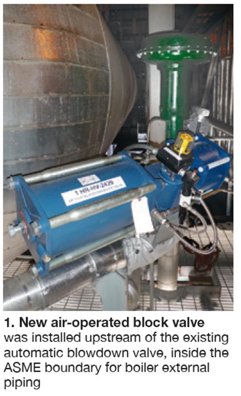
Thus plant personnel decided to install an automatic full-port ball valve upstream from the existing automatic control valve to eliminate the risk of flashing. A 2-in., 2250-psig, air-actuated and metal-seated bidirectional ball valve from ValvTechnologies Inc was selected for this service (Fig 1). The ball valve is equipped with a Morin fail-closed, spring-return actuator and position limit switches.Solution. Research by plant personnel indicated that manual isolation valves were not a viable solution for a plant cycling daily. They worked with the supplier of the replacement angle control valve to investigate if other trim materials or valve types could be used to reduce or eliminate the blowdown leakage. An automatic replacement blowdown-valve solution could not be identified.
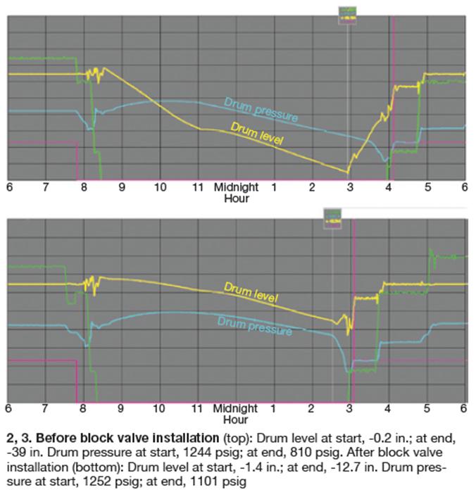
Results. The new block valves showed immediate results. During the first overnight shutdown period following commissioning of the valves, the decrease in HP drum level was significantly less and did not require addition of water to satisfy the GT start permissive the following morning (Figs 2, 3). Additionally, operators did not have to blow down the IP drum during the overnight period and a “450 hold” was not required during the morning start.The new valves were installed near the HP drum on each HRSG during a recent outage and have been in service for several months. The open/closed block valves are controlled automatically from the DCS. Limit-switch feedback to the control room provides assurance of proper opening and closing of the block valve.
Additional longer-term benefits include these:
• Reduced both makeup (city water) requirements and the consumption of demin regeneration chemicals (sulfuric acid and caustic soda).
• Improved drum chemistry, because large swings in drum level have been eliminated. Consumption of chemicals for boiler water treatment also has been reduced.
• HP-drum thermal stresses have been reduced by eliminating the addition of large quantities of cold water after an overnight shutdown.
• Decreased start-up times by avoiding costly “450 holds.”
• Avoided maintenance costs that would have occurred from using the blowdown valve to shut off flow had the block valve not been installed.
Project participants:
Chad Harrison, maintenance manager; Ted Karabinas, maintenance technician; and Scott Courtois, I&C technician.
Breaker retrofit protects transformer
Best of the Best award recipient
Challenge. Newington Energy Facility was designed having the steam turbine/generator (ST) directly connected to the 18/345-kV step up (GSU) transformer with no low-side generator breaker. This was not problematic during the first six years of commercial service when the site averaged only 12 combined-cycle starts annually.
However, reliability problems were encountered in cycling operation (today the plant averages 230 starts annually) and four forced outages were experienced within two years. Investigation identified several related risks associated with near-daily synchronizing across the 345-kV breaker, including the following:
• The breaker was designed as a transmission breaker and the OEM said there could be reduced overhaul intervals and potential reliability issues if used in a daily synchronizing application.
• In the event of a GSU fault, the inability to isolate the generator from the transformer would allow the generator to continue to feed the fault as it spun down and the field decayed, increasing the damage caused by the original fault.
• With the current design, a stuck generator-breaker fault would cause the site’s transmission interconnect to trip, initiating a black-plant, full-load rejection and trip of the gas turbines. This scenario would leave all three turbines coasting down with dc oil pumps operating and increasing the risk of collateral damage plant wide.
• With the transformer de-energized each night, it was subject to hundreds of thermal cycles annually. This was of particular concern during winter months when ambient temperatures onsite frequently can reach the single digits.
Solution. After extended study and analysis, the plant elected to install a purpose-built 18-kV generator breaker in the bus between the generator and the GSU on a fast-track schedule. The project was complex and required an engineering firm with mechanical, electrical, civil, and structural capabilities. The initial design effort required a detailed accounting of all control and protection functions, some of which would require relocation while others would be duplicated on the new breaker.
A new breaker failure scheme also was designed and incorporated into the existing protection functions. Plant engineers worked with the generator OEM to modify and re-commission the synchronization-program logic in the generator controls. The new breaker also required incorporation of alarm and status information into the site DCS and historian, as well as into two different offsite Scada systems.
The project involved revision or creation of over 100 detailed drawings. Multiple iterations of site and engineering reviews were conducted to ensure interconnection accuracy. An onsite as-built termination audit was conducted to ensure the site’s drawings accurately reflected the as-installed condition before design work began.
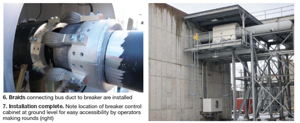
Site staff also was able to incorporate several O&M-friendly features that normally might not be included during new plant construction. Steel work includes a 360-deg, 100% deck to allow access to all areas of the breaker, including the underside linkages, without the need for staging. A roof was incorporated to mitigate weather impacts.Plant personnel took a very conservative and collaborative approach to commissioning, assembling a team consisting of the design engineer, the breaker OEM, the site’s relay testing firm, and a ST controls engineer experienced in new-unit commissioning. Five days of extensive testing concluded by closing the new breaker with a simulated turbine speed, energizing the 18-kV bus up to the open generator links. All control, protection, status, and alarm functions on the new breaker and on the original breaker were demonstrated during the testing.
Eric Pigman, Ed Sundheim, and Chad Harrison (l to r)
The control panel was relocated to ground level to reduce the vertical ladder exposure to employees. Long-lasting LED lighting was incorporated to reduce re-lamping needs. Lastly, a detailed alarm annunciator at the breaker’s local control cabinet was specified to allow the site to determine the exact cause of an alarm without resorting to detailed trouble shooting of the typical “daisy chained” generic trouble alarm. These improvements will contribute to the long-term success of the project.
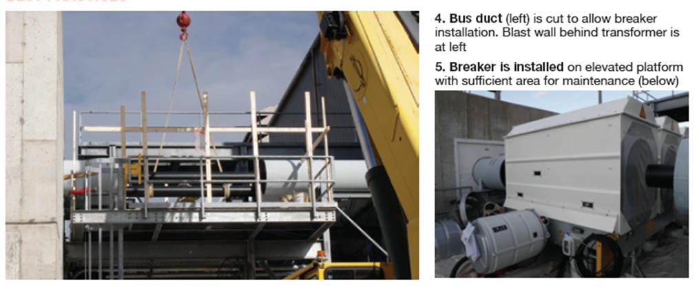
Results. The initial engineering purchase order was issued Mar 28, 2012 and the breaker order placed in early May. The generator breaker was installed during a 14-day planned outage in November 2012 (Figs 4-7). Installation went as planned with no significant issues. When the plant was restarted, the new generator breaker closed without issue on the first pass of the synchroscope. The breaker has effectively reduced or eliminated the risks identified when the site entered cycling service. The project is expected to improve long-term reliability and maintainability of the plant, whether it continues in cycling service, or resumes base-load operation at some point.
Project participants:
Eric Pigman, plant engineer; Chad Harrison, maintenance manager; Scott Courtois, I&C technician
Triple-redundant sodium analyzers protect equipment, personnel
Best Practices Award recipient
Challenge. Newington Energy Facility’s steam-turbine condenser has nearly 9000 titanium B338 Gr 2 tubes with an 0.020-in. wall; it’s saltwater cooling tower operates at approximately two cycles of concentration. The plant as-built provided for monitoring of condensate pH and specific and cation conductivity—but not sodium. The distance from the condenser to the analyzers in the sample laboratory was such that a step change in concentration would take about 45 minutes to detect. Therefore, one of the first modifications made to the facility was installation of a condensate sodium analyzer and cation conductivity analyzer in proximity to the condensate pump discharge. The analyzers were wired to the DCS and signals transmitted to the PI data historian.
The condensate sodium and cation conductivity analyzers were pivotal in providing quick, reliable identification of a sodium excursion during the plant’s first condenser tube leak in 2008. Once the instrumentation readings were confirmed, it allowed operations to safely shutdown the facility within 45 minutes in a controlled fashion to prevent steam system equipment damage.
The analyzers again protected the plant equipment in 2012 when a tube “weeper” was detected, allowing site staff to plan a maintenance outage to locate and isolate the tube leak. In this instance, it was estimated that the leakage rate of circulating water into the condensate was less than 5 ml/min.
As the adage “Murphy’s Law” is professed, condenser leaks won’t occur on a weekday morning when the plant is fully staffed and additional personnel are available to assist with troubleshooting and analysis. Leaks will occur during a weekend midnight shift when operations staff is reduced and where the decision-making matrix is based upon available information streaming into the operating console, operator training, alertness, and experience.
Considering the plant’s cycling operation, condenser materials, previous condenser tube leaks, combined-cycle fleet experience with saltwater condensers, and single-point of analysis for condensate system purity, the analyzers had become critical to the protection of steam-cycle equipment. Facility management decided that a more robust detection design was needed to provide the operations information necessary for safe, reliability facility operation. A triple-redundant analyzer system with voting logic was needed for this application.
Solution. Site personnel worked with two reputable vendors to install demonstration sodium analyzers at the plant. They were operated for approximately three weeks, providing staff the opportunity to evaluate both analyzer response to daily cycling and maintenance and calibration requirements. Results of the demonstration units were compared to those from the existing analyzer. Ultimately, an updated version of the existing analyzer was chosen—the Thermo Scientific 2111XP.
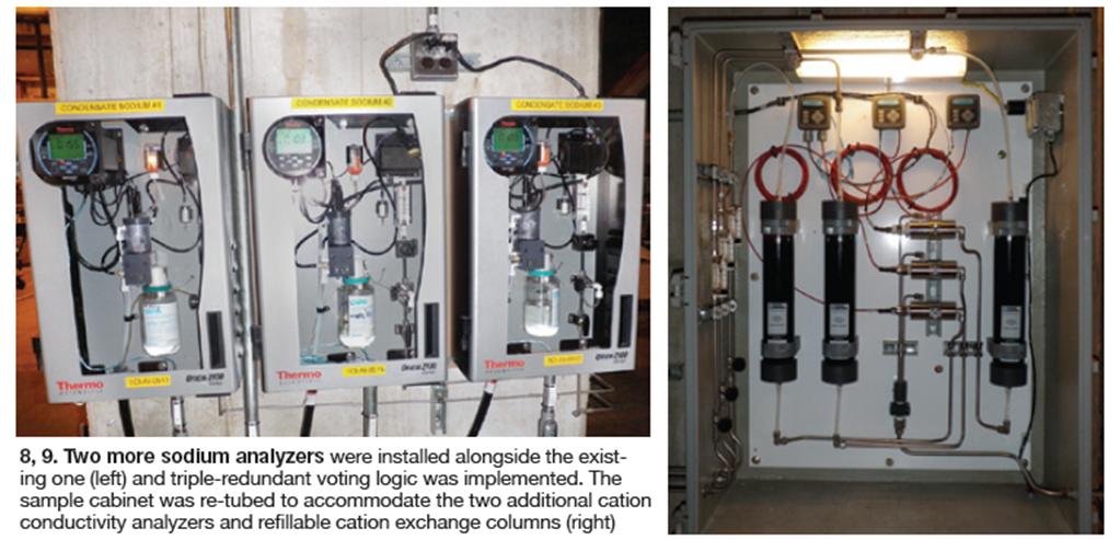
Since conductivity analysis technology is relatively straight forward, the site simply added two more analyzers alongside the existing one (Fig 8). The sample cabinet was re-tubed to accommodate the two additional cation conductivity analyzers and refillable cation exchange columns (Fig 9).
Results. The triple-redundant analyzers are in a short “break-in” period where the analyzers are being monitored to ensure that no unnecessary trips take place. This period is instrumental to understanding the stability of each analyzer, as well as the relative analysis difference among the analyzers, since the typical condensate sodium concentration is less than 0.20 ppb. Next step is to enable the DCS voting logic to automatically initiate a plant shutdown if the sodium analyzers and cation conductivity analyzers indicate a saltwater intrusion into the condensate system.A plant I&C technician programmed the triple-redundant voting logic to the DCS for both the condensate sodium and cation conductivity analyzers. The resulting triple-redundant system will provide objective information when faced with a potential saltwater intrusion. This better protects equipment and relieves the operations staff from having to decide whether or not to trust the analyzers and shut down the plant.
Project participants:
Joshua Leighton, Operations Manager; Scott Courtois, I&C Technician; and Eric Pigman, Plant Engineer