


Inspect steam valves for stellite delamination
By Kim Bezzant, Structural Integrity Associates Inc
Stellite liberation from large valves installed in high-pressure (HP) and hot reheat (HRH) steam systems serving F-class combined cycles has emerged as an important industry concern. Tight shutoff of parallel-slide gate and non-return globe valves has been compromised in some cases, based on feedback from plant personnel; steam-turbine components also have been damaged.
EPRI has established a committee on “Cracking and Disbonding of Hardfacing Alloys in Combined-Cycle Plant Valves” to dig into the details. The work, funded by several sponsors, began early this year. John Shingledecker (jshingledecker@epri.com), the technical manager for this program, said the project timeline is estimated at 14 months. The first formal review of industry experience is incorporated into the program for the upcoming EPRI Fossil Materials and Repair Program Technology Transfer Week, June 24-28, in Destin, Fla.
Owner/operators, valve manufacturers and service organizations, and other interested parties expect one outcome of the R&D effort will be a more reliable process for the bonding of stellite to discs, seats, and slides for valves subjected to steam temperatures approaching 1100F, as well as to rapid quenching caused by improperly operating desuperheaters and/or drain systems. The solution also may require changes to current industry inspection, operating, and maintenance procedures.
Industry experience suggests inspection of large steam valves at plants built during the late 1990s and early 2000s at the next hot-gas-path (HGP) or major inspection if this has not been done previously (see sidebar in this article). A visual inspection will confirm stellite liberation, dye penetrant testing will reveal cracking not visible with the naked eye, and a straight-beam ultrasonic examination will identify disbonding.
But before opening your valves, be sure to have a game plan for repair or replacement in case you find damage. Failure to plan ahead could significantly add to your outage schedule. Here are your options if damage is found:
- Replace the existing valve with a new one.
- Cut the valve out of the line and send it to the manufacturer or a qualified third-party shop for repair.
- Repair the valve inline.
Owner/operators who have already faced repair/replace decisions suggest that you factor the following facts into your decision:
- The lead time for new valves may extend beyond a year.
- Shops capable of doing quality valve work and welding generally have a backlog.
- Quality repairs are difficult to make inline because of preheat and access requirements.
- Field-service organizations with the requisite in-situ valve repair experience are extremely busy.
- There is no industry standard for applying hardfacing. Manufacturers and repair firms have their own procedures and they should be qualified metallurgically before work begins on your valves. Plus, owner/operators are advised to carefully monitor repair work to the qualified written procedure.
Case history
The D11 steam turbine for a 2 x 1 7FA-powered combined cycle recently experienced an increase in HP-cylinder inlet pressure as well as a slight decrease in electrical output. Design steam conditions for the HRSGs were 1450 psig/1070F at the HP outlets and 450 psig/1067F at the HRH outlets. Lifetime operating hours totaled about 45,000, starts (mostly warm) 150.
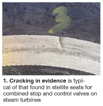
Plant personnel began their investigation by following the recommendations of the OEM’s Technical Information Letter (TIL) 1629-R1, “Combined Stop and Control Valve Seat Stellite Liberation,” released Dec 31, 2010. The inspection team found that no stellite had been liberated from the valve seat; however, multiple cracks were found in the stellite inlay (Fig 1).
Important to note is that the two stellite alloys typically used for hardfacing of valve seats and discs are Stellite 6 and Stellite 21, trademarked products of Deloro Stellite Group. Since investigators did not know whether Deloro cobalt-based hardfacing alloys were used in the fabrication of these valves, the generic names Alloy 6 and Alloy 21 are used here.
This was not the first inspection of the combined stop and control valve (CSCV). It had been inspected during the 2009 major, shortly after the TIL was first published on Jan 30, 2009. The original TIL 1629 only called for visual (VT) and liquid-penetrant (PT) inspections. No cracking was found at that time. As noted above, Rev 1 of the TIL requires ultrasonic inspection, to identify any lack of bonding between the inlay and the base metal, if the unit has less than 50 starts.
Significance of the 50 starts: After that number of cycles, metallurgists believed any disbonding would have propagated to the edge of the inlay and could be identified with VT or PT. While the steamer had more than 50 starts at the time of the 2009 inspection, no PT indications were found at the edge of the hardfacing inlay. However, the ultrasonic inspection in 2012 revealed significant disbonding of the inlay.
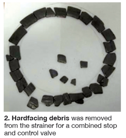
A borescope inspection of the HP turbine revealed significant damage to diaphragms and rotating blades in several stages. During CSCV disassembly, metallic debris was found in the valve’s strainer (Fig 2). Analysis verified that its composition was consistent with the hardfacing alloy used on valve seats. Some debris had cut through the strainer and damaged HP turbine components.
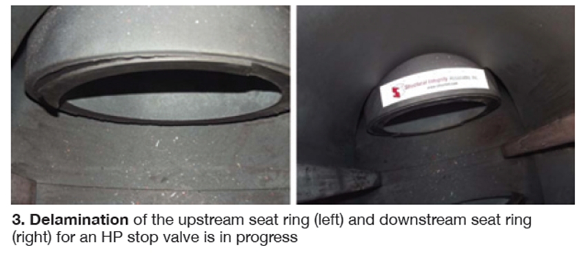
Three HP gates.Based on these findings, plant management decided to check other high-temperature valves for damage. The inspection list included these eight valves on each unit:The next step was to identify the source of the hardfacing debris. A key clue: Operations personnel had reported that the HP stop valves were not sealing during shutdown. They were disassembled and the Unit 2 HP line stop was found with stellite missing from both the upstream and downstream seats (Fig 3). The Unit 1 HP line stop had its stellite in place, but showed signs of significant disbonding.
- One HP non-return globe.
- One CSCV.
- One HRH gate.
- One IP gate.
- One cold reheat (CRH) check.
Inspection results: Disbonding of hardfacing was identified on all HP and HRH valve seats; also on the seat and guide rails of the HP non-return globe valves. The IP and CRH valves showed no disbonding. Further investigation revealed that the hardfacing for the HP and HRH valves was applied using the Plasma Transferred Arc Welding (PTAW) process and for the HP non-return globes it was the Shielded Metal Arc Welding (SMAW) process.
Also, hardfacing on the HP and HRH gate-valve seats and discs was of bi-layered construction: An Alloy 21 buffer layer applied to the Grade 91 seat rings and an Alloy 6 finishing layer. The former is a low-carbon CoCrMo alloy with the AWS/ASME solid-wire filler-metal designation ERCoCr-E. It is characterized by reasonable ductility and metal-to-metal wear resistance at elevated temperatures. By contrast, Alloy 6 is a high-carbon CoCrW alloy with an AWS/ASME solid-wire designation of ERCoCr-A having improved metal-to-metal wear resistance at elevated temperatures.
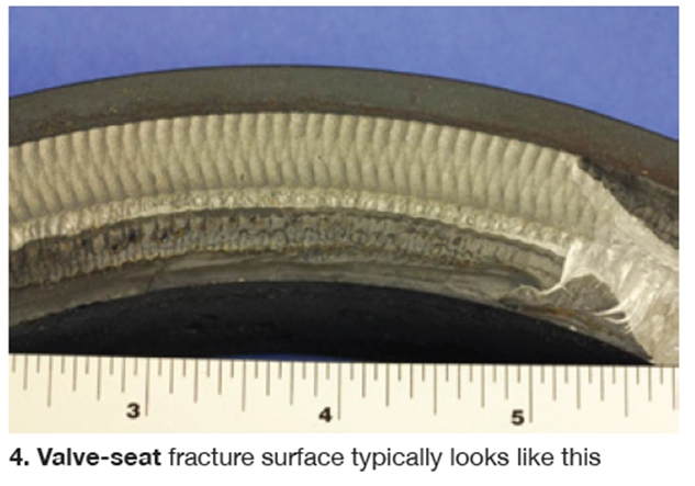
Evaluation of the fracture surface raised concern that the failures were located in the Grade 91 base metal and might be similar to other creep-related dissimilar-metal failures found in Grade 91 piping (Fig 4). However, examination of the Grade 91 base metal revealed a tempered martensitic structure consistent with material that had been properly heat treated.The valve manufacturer’s service technician said that prior to the millennium, Alloy 6 typically was used for hardfacing of valve seats. But multiple disbonding incidents prompted his company to adopt the bi-layered approach. The thinking was that the improved ductility of Alloy 21 would minimize the risk of disbonding while the finishing layer of Alloy 6 would maintain a high degree of metal-to-metal wear resistance. Research revealed other valve manufacturers had similar issues with disbonding and they are using Alloy 21, stainless steel, or Inconel as buffer layers.
The heat-affected zone (HAZ) created by the deposition of hardfacing, while of a normal structure for Grade 91 material, was wider than normally would be expected given the thickness of the overlay. This indicated that relatively high heat inputs were used during the PTAW application of at least the buffer layer of Alloy 21. There was no evidence of creep damage in the Grade 91 HAZ.
Cracking that contributed to the disbonding of the hardfacing from the base metal developed near the interface between the valve seat and the stellite. It was caused largely by brittle fracture that had propagated through the Alloy 21 buffer layer. In some areas, the cracking propagated very close to, or along, the dissimilar-metal interface between the Grade 91 and Alloy 21.
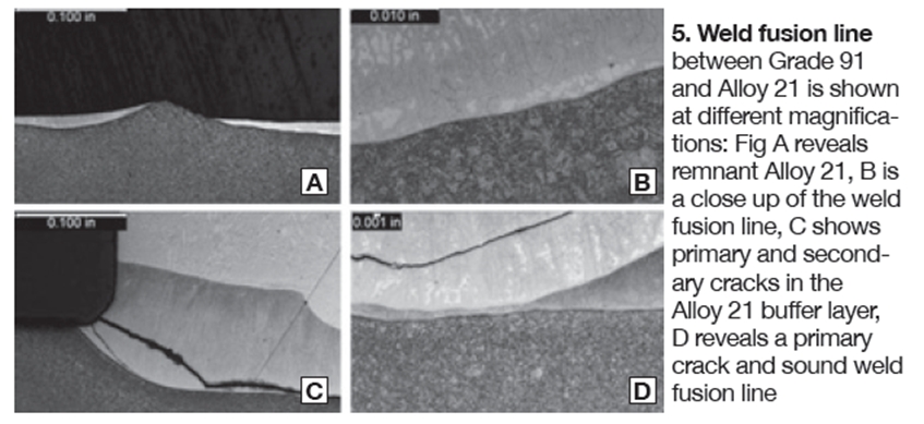
Energy-dispersive X-ray spectroscopy (EDS) was performed on several samples to determine the chemical composition of the hardfacing layers. This analytical is used for elemental analysis of a material sample. The results showed high levels of iron dilution in the Alloy 21 buffer layer—ranging from 38% to nearly 70%.However, in these areas the fracture location appeared to be the result of the orientation of the brittle fracture rather than any unique “weakness” associated with the interface (weld fusion). Metallurgical evidence suggested that the dissimilar metal interface was not uniquely susceptible to the cracking and was only indirectly involved in the accumulation of damage (Fig 5).
SIDEBAR: Valves didn’t get the respect they deserved
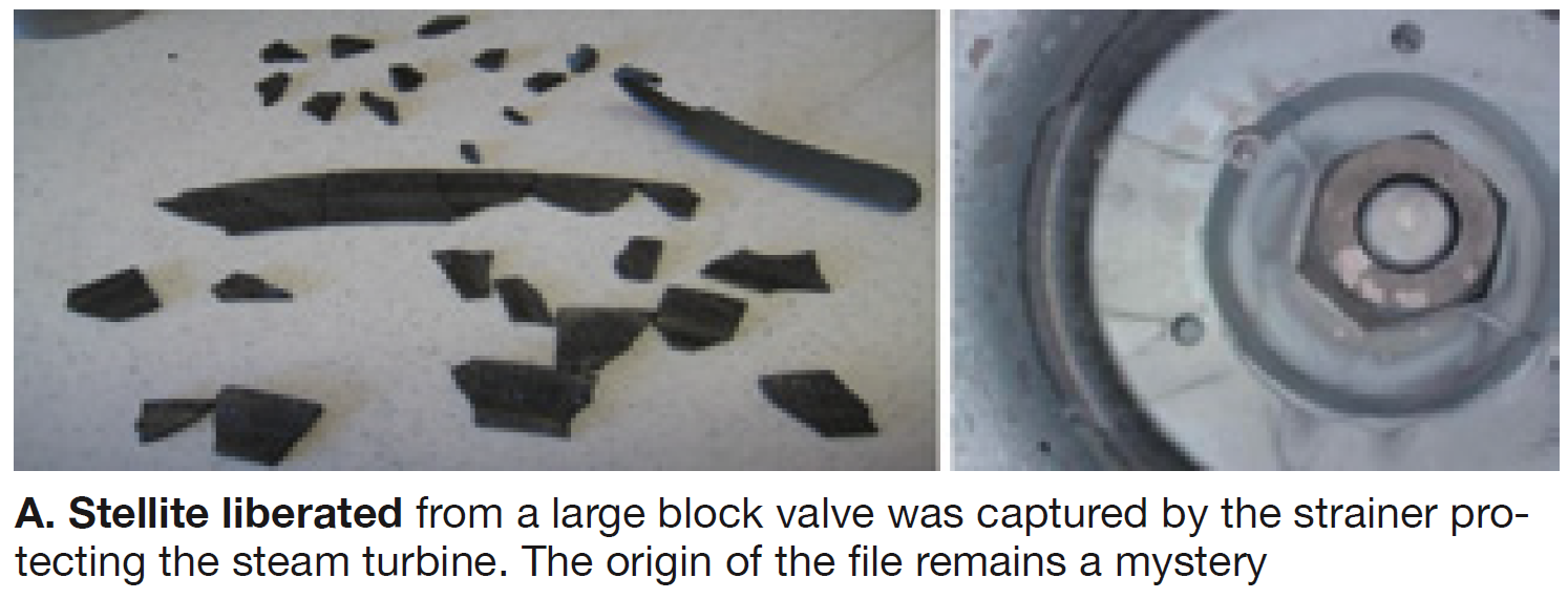
The editors first learned of stellite delamination in a large valve designed for high-pressure (HP)/high-temperature steam service at the 2009 7F Users Group conference. But all the attention that incident received was a brief mention late in a long user presentation profiling the major inspection of a combined-cycle plant. More than 200 owner/operators were in attendance, yet no questions were asked about the issue—at least none the editors can recall—and it was quickly dismissed. Fig A shows stellite liberated from the seat of a 20-in. hot-reheat block valve installed at that presenter’s plant and collected in the strainer for the steam turbine’s combined stop and control valve.
Another alert concerning stellite liberation came from GE Energy, which issued Technical Information Letter 1626 on Jan 30, 2009. It advised steam-turbine owners to check the condition of the stellite inlay sections used in fabricating seats for the OEM’s combined stop and control valves. Revision 1 of that TIL, dated Dec 31, 2010, recommended a “one-time seat stellite inlay UT inspection during valve installation or next planned maintenance inspection.”
Yet another alert regarding stellite cracking was sounded by Ed Sundheim, director of engineering for the North American Energy Alliance LLC, Princeton, NJ, who had intended presenting on the subject at the spring 2011 conference of the Combustion Turbine Operations Technical Forum™, but the lunch bell sounded before he got to the podium.
Instead, Sundheim provided the editors his notes to develop the CCJ article, “Don’t forget to inspect your valves,” a case history charting the inline repair of F91 parallel-slide gate valves at Newington Energy LLC. It was published in the 2011 Outage Handbook; access via www.ccj-online.com using the search function.
More recently, the Dogwood Energy Facility was recognized with a Best Practices Award in 2013 for its efforts in the identification and repair of a cracked seat on the 12-in. HP stop/check valve for one of its HRSGs. Except here, the seat material was Type-316 stainless steel; no stellite was involved. Get the details on p 54.
The industry recently learned of many more incidents of stellite liberation. CFM/VR-TESCO LLC (formerly Continental Field Machining), a leading valve services company, reported earlier this year at a meeting of the Valve Manufacturers Assn (VMA) that in 2011 and 2012 it had repaired 50 valves manufactured from F91 (forged body) or C12A (cast body) and ranging in size from 12 to 24 in. More than half of these jobs involved stellite liberation.
The repair projects profiled were split roughly 50/50 between valves within the Code boundary and those that were part of the boiler external piping. Repairs on the former were performed according to guidelines presented in Section I of the ASME Boiler & Pressure Vessel Code and in the National Board Inspection Code as well as jurisdictional requirements. Valves outside the Code boundary were performed according to ASME B31.1.
Background
The editors spoke with owner/operators, a valve manufacturer, and a service firm, as well as with Kim Bezzant of Structural Integrity Associates Inc, regarding issues associated with high-temperature steam valves. It seems that many problems the industry is experiencing today can be traced to a general lack of respect for valves and inattention to detail regarding their manufacture, installation, operation, inspection, and maintenance.
Success in all aspects of equipment and system design and manufacture/construction hinges on good specifications and involvement by the owner, or its representative, in the work contracted to others. Price always is important until breakdowns force a plant out of service. Then the quality that should have been built into the equipment suddenly becomes important. As the Dutch are fond of saying, “Too soon we grow old, to late smart.”
Speaking with owner/operators you get the feeling that valves were considered pedestrian equipment. No owner the editors spoke with went to the fab shop to inspect the product during manufacture or to verify inspection results. One said valves were part of the EPC contractor’s scope of supply and only their employees were allowed in the shop, by contract. Did the EPC send someone to the shop? Certainly unlikely in one case examined where the welding was so poor even an inexperienced inspector likely would have rejected the job.
Someone else told the editors he thought his plant’s valves had forged bodies, but they actually were less-expensive castings. At least some of those castings were made in far-off places where QC didn’t exist 10 years ago, which is why the industry still hears about defects in valve bodies. You might also consider checking the bodies of your high-temperature valves when inspecting for stellite cracking and disbonding. Recall how surprised many users were when they found out that their P91 didn’t meet hardness specs, the wrong weld filler material was used, P91 was welded to P22 in error, etc.
One owner’s experience
Discussions with a boiler engineer for an owner of multiple combined-cycle plants equipped with HRSGs and valves from several different suppliers revealed how pervasive the stellite cracking and disbonding issue is. His company implemented a fleet-wide survey of its large steam valves and now tracks on an ongoing basis the inspections, detailed findings, and repairs for each critical valve.
This owner’s best practice today regarding inspection is to open and inspect valves on a two-year cycle, and have a capital spare. All components are checked—including springs, stems, discs, and seat rings. Straight-beam ultrasonic examination is used to locate any disbonding between the hardfacing material and the valve body. This is important: Where there is disbonding, cracking usually follows.
Don’t chintz on inspections, the boiler engineer advised. A proper job requires top talent. The company you select should be experienced in this work, have the proper coupons for calibrating its instrumentation, and provide a savvy technician to conduct the inspection.
Corrective action by this owner, when necessary, is guided by inspection findings and may differ from plant to plant depending on the damage encountered, because there are no industry standards for hardfacing and some other required repairs. The utility expects the EPRI task force discussed in the main text to provide a much-needed guideline for applying hardfacing alloys in a manner that minimizes, and possibly eliminates, the damage being experienced today. Its expectation of a viable EPRI solution was echoed by virtually all industry participants interviewed—including other owners, operators, manufacturers, and repair firms.
At the first of this owner’s F-class combined cycles to inspect its HP steam valves, engineers found cracks in the integral seat for a stop/check valve that propagated through the stellite and into the valve body. A field repair crew machined off the hardfacing, chased the cracks to the bottom and repaired the body with Grade 91, and then refaced the seat with stellite.
Operability issues experienced with a parallel-slide gate in HP steam service at another plant in the fleet raised a red flag and engineers inspected all four HP valves on its two HRSGs during an outage planned for 10 days. That outage was extended by about a month and half because of the valve work.
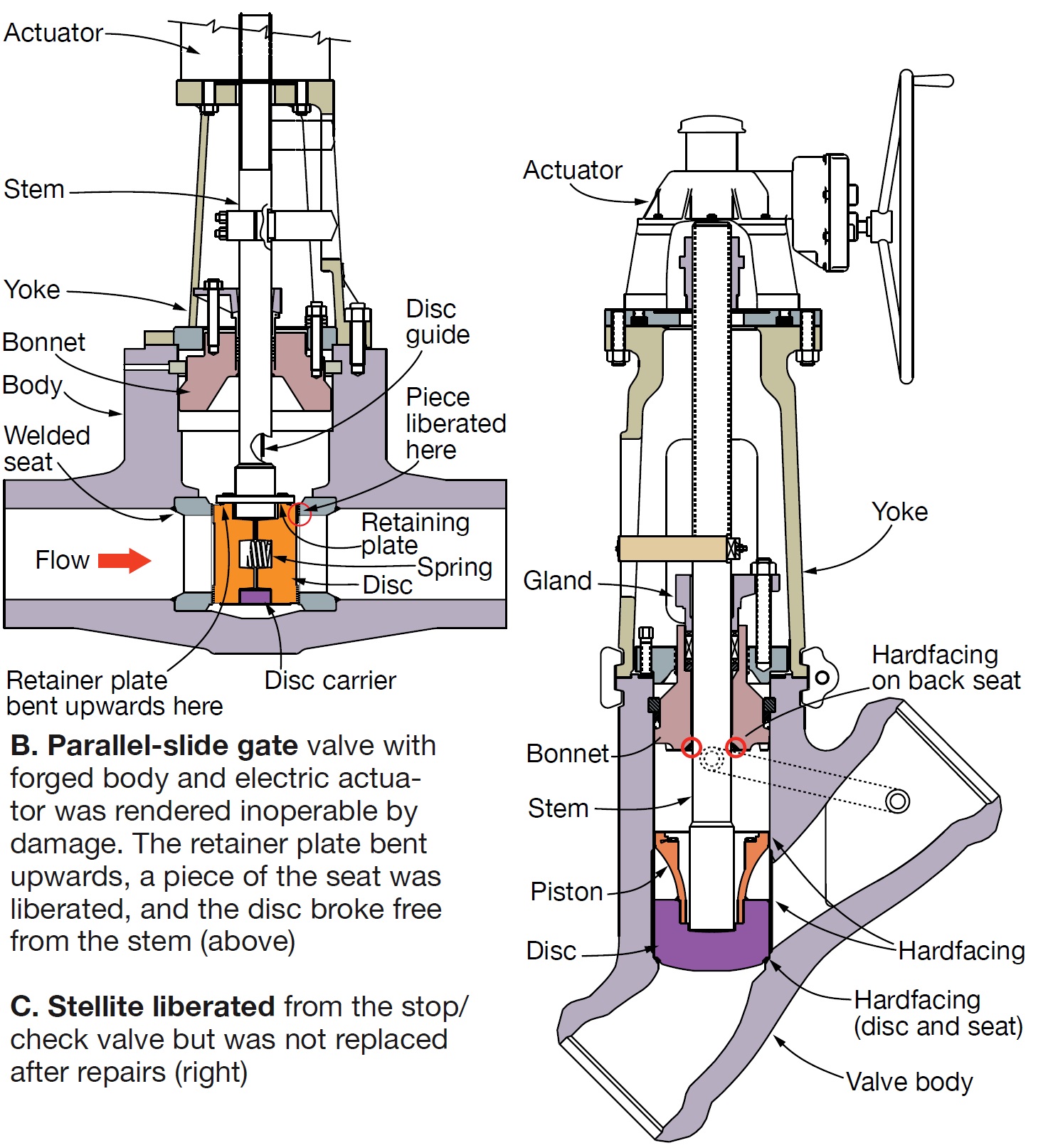
Cracking of seats and discs was found on both parallel-slide gate valves (Fig B) and both stop/checks (Fig C). Some of the liberated stellite still has not been found. All four valves were removed and send to a qualified shop for repairs.
The parallel-slide gates had serious issues. The retainer plates in both either broke or bent and contributed to body damage; pieces of stellite liberated from the seat rings on both gates. In addition, the disc came off the stem on one of the valves and resultant chattering caused still more damage. These valves were completely overhauled and repaired; Grade 91 material was built up where necessary and Stellite 21 hardfacing was applied in wear areas. In effect, the valves were restored to their original condition.
For the stop/checks, hardfacing was machined off and the Grade 91 material dressed; stellite was not reapplied. Given the company’s experience and the state-of-the-art in hardfacing, Grade 91 seating surfaces were viewed as the least-risk alternative.
Another F-class 2 x 1 combined cycle in the fleet recently inspected its HP valves. Seats for the gate valves are integral with the bodies and dye penetrant identified cracks in both, but there was no evidence of disbonding. Cracking of the stop/check seats also was in evidence, with no disbonding. However, the guide ribs were galled. Stellite was removed and the guides are now Grade 91 with no hardfacing.
Lessons learned. Before the owner inspects for the first time valves on another of its combined cycles approaching 10 years of service it will take delivery on two new HP gates and stop/checks. Experience indicates that the chances of finding valves as-new is unlikely and alternative with least schedule impact is to cut out the existing valves and drop in new ones.
In sum, the owner’s near-term strategy has been to minimize operational risk by verifying the integrity of the fleet’s HP valves first. These valves, it believes, have the most severe service conditions. Long-term thinking is that EPRI will have established best practices for steam valves before inspection of hot-reheat and other valves is necessary.
The manufacturer’s view
Dr Nabil T Tarfa, who recently joined Velan as VP materials and process technologies, shared his thoughts on cracking and disbonding of hardfacing in combined-cycle service. Montreal-based Velan is one of the electric-power industry’s leading suppliers of valves for high-pressure/high-temperature steam service. Most of company’s valves have forged bodies, Tarfa said, because forgings have a more uniform structure than castings and generally are of a higher quality.
Asked why he believes steam valves for F-class combined-cycles are experiencing so many problems of late, Tarfa summed up his thoughts succinctly: There’s a gap between the service conditions specified by the buyer and how the equipment is being operated. He said Velan is investing considerable time and effort to determine both the root causes of the problems experienced and how to address them.
The company is a participant in the EPRI research program on cracking and disbonding of hardfacing alloys and also is sponsoring a research project with a Canadian university to identify factors contributing to the failures and how to address them. He believes that an effective solution hinges upon an open exchange with users, to learn more about how plants are operated in the competitive generation industry.
Tarfa said there are several important factors to consider in analyzing the cracking/disbonding problem, including these:
- The metallurgical nature of the bond between the hardfacing material and base metal.
- Temperatures involved, and the times at those temperatures. Plus, numbers of cycles, ramp characteristics, thermal shock caused by quenching of hot metal by condensate, etc.
Pentair, which provides a wide range of valves to power producers under several brands—including Crosby, Sempell, Dewarance, and Clarkson—offered a brief overview of hardfacing issues at recent meeting. The speaker acknowledged that “stellite failures are an industry issue,” and stated the following:
- Each OEM must have a written procedure, which must consider (1) the shape, dimension, and accessibility of parts to be welded, (2) range of dilution to achieve a specified hardness, (3) where the job will be performed—in the field or in the shop, (4) welding position, and (5) level of automation.
- The application is a consideration that must be reviewed.
- The application of weld overlay is critical.
- The right material for the right application.
Finally, “For determination of hardfacing procedures and application of weld material, shape of components, used materials, and operating conditions must be considered. A general rule to have a unique standard for deposition of of hardfacings is not feasible. Each manufacturer has to select and qualify individual processes for hardfacing.”
Field repairs
CFM/VR-TESCO LLC (it stands for Continental Field Machining/Valve Repair-Technical Service Co LLC) does the lion’s share of its business in powerplants—about 90%, in fact. Several people the editors spoke with believe it to be the “go to” firm for in-situ valve repairs. An overview of what CFM presented before the VMA meeting mentioned earlier offers combined-cycle owner/operators valuable perspective on the extent of the industry’s valve challenges.
Most of the ASME Section I repairs the company has completed can be segregated into these three groups:
- Valves requiring seat replacement.
- Removal and rewelding of integral seats.
- Repair of cracks in the valve body, guide ribs, and/or disc guides.
Half of CFM’s “R” stamp repairs were on valves with SA217-C12A bodies that required replacement of seat rings. The partial-penetration welds holding the seat rings to their respective valve bodies were cracked—the majority all the way around, allowing the ring to fall out of the seat pocket. Portions of the hardfacing was missing from some of the seats. All of the valves with Type-316 stainless steel seats were cracked 360 deg and were replaced with seats of A182-F91or A387 Grade 91 Class II materials.
The remainder of the repairs were on integral valve seats. Most (85%) of those valve bodies also were made from SA217-C12A material. All valves had cracks in the seat-area hardfacing going back into the base material. The majority also had cracking in the guide ribs. In some cases, the stellite had become disbonded from the base material and had moved downstream. This required removal of the remaining stellite and undercutting of the base material. After the base metal was built up, hardfacing was applied.
The majority of the valves repaired under B31.1 (those outside the ASME Code boundary) were parallel-slide gate valves with bodies of A217-C12A. Seat rings were of F91 and P22 materials. Defects were the same as those found on the Section I valves: (1) Seats cracking in the heat-affected zone on the body side of the body-to-seat-ring weld. (2) Stellite breaking off the seat-ring face and entering the steam system.
Welding procedures. Users might consider investing time to learn about stellite and welding procedures for hardfacing. If you have responsibilities on the steam side of the plant, you’re likely to be involved in valve repairs at some point. The Deloro Stellite website offers a good backgrounder on hardfacing materials and such pertinent welding processes as manual metal arc, tungsten inert gas, metal inert gas/metal inactive gas, and plasma transferred arc.
Cobalt-based hardfacing alloys usually are considered for high-temperature applications because of their wear- and oxidation-resistant properties at elevated temperatures. These alloys rely on carbides for wear resistance and typically contain 24% to 32% chromium for oxidation resistance, plus 3% to 14% tungsten or molybdenum for added strength and for their carbide-forming ability.ranges. But the Alloy 21 buffer-layer hardness, which ranged from 39 to 70 Rockwell C (most readings were above 50), was well outside the range expected for this material. Deloro Stellite says the hardness of its Stellite 21 typically is 27 HRC and can work-harden up to 40 HRC.
Low-carbon hardfacing alloys, such as Alloy 21, which has 0.15% to 0.45% carbon, are reasonably ductile and provide metal-to-metal sliding wear resistance and cavitation erosion resistance. High-carbon alloys, like Alloy 6 (0.9% to 1.4% carbon), have limited ductility, but offer increased abrasion resistance.
It would appear that the use of Alloy 21 as a buffer layer was an attempt to interpose between the Grade 91 base metal and the Alloy 6 wear layer a layer of more ductile material to better tolerate dynamic loads. However, the properties of the Alloy 21 buffer layer were altered significantly by changes in the weld-metal chemistry resulting from excessive dilution of the hardfacing during welding.
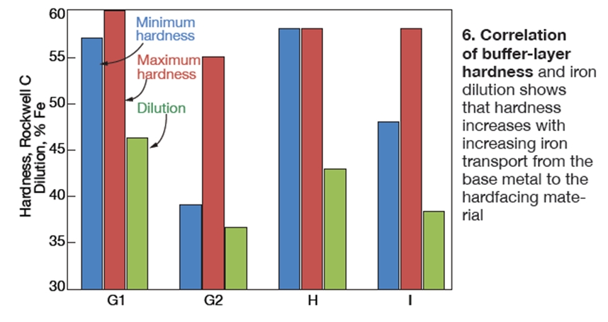 Fig 6 shows the correlation between hardness values and the level of iron dilution for the Alloy 21 buffer layer. While iron was used as the basis for calculating the percent dilution in this case, other key elements would have changed similarly. Note that as the level of dilution increases, the maximum hardness of the hardfacing deposit also increases. Thus the high rate of iron dilution into the Alloy 21 buffer layer of this valve seat produced a very hard layer with substantially reduced ductility.
As indicated above, investigators assumed that the intent of the Alloy 21 buffer layer was to provide a ductile layer under the final Alloy 6 layer. This is consistent with one of the recommendations from Stoody, a respected provider of hardfacing alloys (access “50 Hardfacing Tips” at http://victortechnologies.com/stoody): “Never put a tough ductile weld deposit on top of a harder, more brittle hardfacing deposit. Such deposits will spall, and lift off the part. The hardfacing alloy always should be applied on top of the more ductile material.”
Although it appears that the valve manufacturer attempted to do this by applying an Alloy 21 buffer layer, the level of iron dilution into the buffer layer apparently created the situation Stoody warned against—a softer deposit on top of a harder deposit, which resulted in disbonding of the hardfacing overlays.
To identify a possible driving force for crack growth, steady-state and transient heat-transfer and thermal stress analyses were performed using the finite-element method. The analyses included a postulated thermal shock (rapid cool-down) and a typical startup and shutdown thermal transient based on operational data provided by the owner/operator. Both the heat-up and thermal-shock stress analyses identified significant tensile axial stress at the Alloy 21/Grade 91 interface. This tensile stress is a possible driving force for crack growth.
The type of failure associated with the HRSG valve seats described here typically has not been observed in conventional fossil-fired steam-plant valves. For this case, it appears that the disbonding of hardfacing is caused by several conditions, including the following:
- Higher operating temperatures than are normally experienced in conventional fossil-fired units, specifically 1050F to 1080F, versus 1005F.
- Higher rates of cycling, plus operating conditions capable of producing large quantities of condensate that contribute to thermal shock.
- Material combinations not typically found in fossil-fired steam plants—such as Alloy 21 and Alloy 6 deposited on Grade 91.
- Hardfacing layers with high hardness caused by excessive base-metal dilution into the hardfacing overlay.
Although the foregoing case history specifically deals with the valves from one manufacturer using composite Alloy 21/Alloy 6 hardfacing overlay, similar valve-seat failures have occurred in valves of various manufacturers not using buffer layers. Reports from several combined-cycle owner/operators leads investigators to believe the debonding described may be a generic issue.
Finally, if your inspection identifies disbonding, would you continue to operate or shut down to repair/replace the valve? This is not an easy decision to make for at least two reasons: First, the cause of disbonding is not yet fully established and, second, there is no data to predict the propagation rate of disbonding.
If repairs are needed, or if you’re buying a new valve, it would be prudent to specify a limit on base-metal dilution into the first layer of hardfacing of between 10% and 20%, based on what investigators have learned to date. Minimizing base-metal dilution should reduce the hardness levels in the first layer of hardfacing and reduce the potential for disbonding. Qualify a prospective valve supplier or repair services provider by specifying a demonstration to prove their welding process can minimize dilution.
Whether you have experienced disbonding or not, be proactive regarding the review and modification of operating procedures to reduce the amount of condensate produced in superheater and reheater tube bundles during startup and shutdown. Verify, too, proper operation of attemperators to be sure excess water is not entering the steam path. Check your drain system to assure any condensate formed is being removed quickly and completely. CCJ