


This year’s annual HRSG Forum is being conducted in monthly installments. The first was held May 3, 2021. This report is a compilation of the presentation and discussion summaries from the first three meetings (May, June, July). Dig into the details by simply scanning the QR code with your smartphone or tablet to access the recorded proceedings.
Looking ahead, follow www.HRSGForum.com for announcements of meeting dates, times, and content, and for registration links. There is no registration fee for powerplant owner/operators, consultants, and vendors with an interest in heat-recovery steam generators.
Hex chrome, HP-bypass trim erosion addressed in deep dives with the pros
The two issues focused on in the first online HRSG Forum were hexavalent chromium and trim erosion of high-pressure (HP) bypass pressure control valves (PCV). Both are vexing issues for combined-cycle facility operators and even incremental additions to users’ knowledge/experience base are worth paying attention to. Hex chrome is covered here; the following article summarizes key points extracted from the valve panel discussion.
To tackle the hex-chrome issue, venerable HRSG expert and consultant, Bob Anderson, and co-chairman expert chemist/metallurgist Barry Dooley of Structural Integrity Associates Inc, enlisted David Addison, principal consultant, Thermal Chemistry Ltd, a world-class authority on powerplant water chemistry.
Addison began thusly: The tell-tale bright yellowish deposits of the highly toxic hexavalent chromium show up on air/gas side equipment downstream of high-energy chromium-containing piping, especially in areas where water ingress occurs. Typical areas reported out to the industry include gas-turbine hot-gas-path components; steam-turbine hot external components, such as bolts; and HRSG hot-pipe external surfaces.
Hex chrome is a known and manageable problem in the welding of chromium alloys. Protocols for dealing with it are well-established. Turbine OEMs have issued technical bulletins on it. While those bulletins have not specified the chemical form, XRD/XRF testing confirms that it manifests as calcium chromate. Sources of calcium include anti-seize pastes (containing calcium oxide, CaO) and some lagging/insulation materials.
If you see bright yellow deposits on your equipment, first, don’t panic. But also don’t think it is sulfur-bearing. That’s not possible, though some have made that mistake.
Second, make sure you don’t disturb a deposit, until you are ready to remove it completely. Left to its own devices, calcium chromate will not vaporize or melt. When you are ready to remove it, follow protocols to avoid both worker exposure and inhaling the dust (sidebar). The good news is that Addison said he is not aware of any health issues associated with hexavalent chromium from powerplant operations.
Eliminating the calcium source avoids the problem. If possible, select anti-seize pastes and insulating materials with no calcium oxide. Preventing water ingress also goes a long way towards mitigating the problem. Adding a reducing agent will convert the hexavalent form to the benign trivalent form. One OEM recommends spraying an ascorbic acid/surfactant formulation on the deposit, and field experience suggests this works well.
Other areas which exhibit the right conditions for hexavalent chromium—chromium-containing components, oxygen atmospheres, high temperature, presence of calcium, and water ingress—should be suspect, including superheater and evaporator upper and lower crawl spaces, gas-turbine exhaust ductwork (insulation side). Testing is underway to confirm presence in these areas.
Precautions and protections
Follow these recommended precautions and protections when inspecting areas that have tested positive for hex chrome (or suspected of containing the toxic chemical) and/or when removing the material.
Activity: Inspections in areas where hex chrome residues are present but the residues have not been disturbed.
Exposure. Skin absorption, ingestion.
Controls: Eye protection, disposable nitrile gloves, particle-resistant disposable overalls. Plus, no eating, drinking, smoking, or bathroom breaks should be taken without first washing hands and face.
Activity: Removal or disassembly of items with hex-chrome residues present.
Exposure: Skin absorption, ingestion, inhalation.
Controls: All the controls recommended for inspections (above), in addition to the following: P2 respirator and, where possible, ultrasonic cleaning of parts.
Activity: Grinding, wire brushing, finishing, welding, etc, of surfaces with confirmed hex-chrome residue.
Exposure: Skin absorption, ingestion, inhalation.
Controls: All the controls recommended for inspections and removal/disassembly (above), in addition to the following: goggles, upgraded respiratory protection (to powered air-purifying respiratory protection), mechanical ventilation HEPA filters, and use of controls to limit the aerosolization of hex-chrome residues.
Panel digs into the details of trim erosion on HP-bypass PCVs
To address trim erosion on HP-bypass pressure control valves (PCV), HRSG Forum’s Bob Anderson put together a panel of experts—including Ory Selzer, IMI/CCI; Justin Goodwin, Fisher™; Vasileios Kalos, GE Gas Power; and Consultant Joe Schroeder. The erosion occurs when high-pressure steam entrains water droplets (not to be confused with saturated steam) and passes through the valve trim at high velocities “like sandpaper.” The damage can be so severe that some users thought their trim had melted!
Once the trim has eroded, the valve will leak steam and overheat the downstream carbon steel piping.
The bad news is that you can’t buy a valve that avoids this problem. All models are susceptible. Using better trim materials, reducing velocities by increasing the seat diameter by 10 to 15 mm, and/or lengthening the control plug, may buy you some time and keep the valve tighter for a longer period, but that’s about it.
The root cause of the problem lies in details of the HP-bypass piping design and the peculiarities of starting up a multiple-GT/single-steam-turbine combined cycle. The lag cold-start unit (the second GT to start up) on a 2 × 1 design usually is the culprit. Because the HP isolation valve for the common manifold of the main-steam header is closed, something that does not happen for the lead cold-start unit occurs. Reason is that there is no flow path for steam to warm and dry the HP steam pipe between the HPSH outlet and the isolation valve prior to opening the HP-bypass PCV.
Once the PCV begins to leak enough to overheat the downstream piping, the only safe action is to operate with the PCV at its minimum-open position until the valve can be repaired. Opening the desuperheater-water injection valves to cool the piping—with the PCV closed—is, by consensus, “definitely a bad idea,” Get the details by listening to the panel discussion.
Interest in the subject was revealed through the extensive questions delivered ahead of the meeting. One attendee asked if there is another source for the erosion—such as magnetite. Panelists answered that magnetite would pass through all the valves and this erosion is heavily biased towards the HP-bypass PCV. One panelist noted he’d only seen one valve that had experienced solid-particle erosion rather than water-induced erosion.
Another asked about chromium or tungsten carbide materials for the trim instead of Stellite-6, and the response was they weren’t used in steam applications. “Promising alternative trim materials have not seen many operating hours,” one panelist noted, including a temporary repair technique using Inconel 625 or 718 or superalloys with high titanium or aluminum content as a “buttering layer.”
Anderson suggested that establishing a proper steam flow path to warm the piping from the superheater outlet to the common manifold isolation valve prior to opening the PCF is needed to avoid condensate ingestion. This may require enlarging the drain upstream of the isolation valve. Pre-warming the valve body and steam line with warm-up nipples has shown inconsistent experience. One panelist made the wry comment that “spray valves leak and drain valves plug.” So, to will HP-bypass PCV valve trim erode and leak—at least until further notice.
Steam-side oxides, poor NH3 distribution tackled at the second forum
During the HRSG Forum’s second monthly meeting, June 2, 2021, hosted by Bob Anderson and Barry Dooley, close to 130 owner/operator representatives from 34 countries (out of 219 total attendees), were enlightened on two vexing issues with HRSGs: (1) steam-side oxide growth and exfoliation (OGE) from superheater (SH) and reheater (RH) tubes, and (2) the use of computational fluid dynamics (CFD) and field testing to improve selective catalytic reduction (SCR) unit performance.
Judging from the number and quality of the questions for both presenters, these attendees weren’t just staring at their screens. You don’t want to miss listening to recordings of the presentations; simply scan the QR code above with your smartphone or tablet. They are rich in detail with a methodical sequence of illustrations for truly understanding the problems, impacts, and solutions.
Barry Dooley, a senior associate at Structural Integrity Associates Inc, whose experience dates back decades to some of the early work done at the UK’s CEGB, Ontario Hydro, and EPRI on OGE, explained how SH and RH ferritic steels like T11, T22, T5, T9, T23, and T91 are susceptible to oxide growth on inner surfaces containing greater amounts of hematite versus magnetite, which can lead to exfoliation of particles under the right thermal stresses (Fig 1). The progression of formation for different alloys, from laminations in the oxide layer to cracks to exfoliation, is well depicted in the slides.
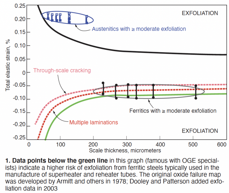
The varying alloy compositions—chromium and molybdenum contents specifically—help determine how fast deposits grow, and the risk of exfoliation. The specific environmental factors are saturated or superheated steam, gas-turbine exhaust temperatures from 1100F to 1150F, use of duct burners, and tube temperatures ranging up to 1200F.
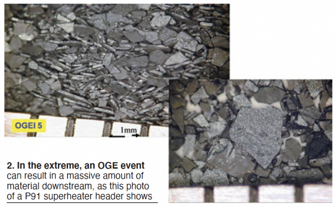
The deposits themselves can lead to tubes operating at higher temperatures, resulting in an ever-increasing oxide growth rate. The exfoliated material causes erosion, plugging, and sticking in valves; erosion of downstream HP and IP steam-turbine inlet-valve and steam-path components; or simply collects in a header (Fig 2). Impacts tend to show up after many thousands of operating hours but of course are aggravated by deep unit cycling and starts/stops, once the oxide reaches the critical thickness for exfoliation. Dooley shows one HRSG case in which material began to exfoliate after only 24,000 operating hours.
Unfortunately, OGE cannot be controlled through steam/water chemistry changes. It’s not dependent on O2 concentrations, but instead on O2 partial pressure. The influence of film-forming substances in the chemistry is uncertain. Shot-peened Type-304H stainless steel and S304H SH tube alloys will exhibit a Cr-rich layer along the surface which slows the rate of exfoliation. “It’s rare for them to exfoliate,” Dooley said.
Among the insights that emerged from the Q&A session:
- No relationship has been developed among operating parameters (for example, total operating hours, number of starts, etc) and OGE to predict its onset before impacts occur.
- Cycle modifications which increase gas-turbine exhaust temperature raise the risk of oxide growth.
- UT analysis can detect oxide-scale thickness but only lab metallographic analysis can reveal the characteristics of the oxide layer critical to OGE.
- Early theorists suspected that steam/water O2 levels contributed to hematite formation, but deeper research has proved this false.
- Small additions to the alloy, like vanadium and tungsten, will alter iron-ion migration patterns.
Improve NH3 distribution to reduce NOx and ammonia slip
Bill Gretta, principal, SCR Solutions LLC, presented two case studies in which a unique field test method combined with sophisticated CFD analysis suggested modifications for improving distribution of ammonia through the SCR catalyst modules to improve NOx reduction and ammonia slip. Old units, and many new ones, are not equipped with a permanent NH3 sampling grid downstream of the SCR, and it’s costly to add, Gretta said.
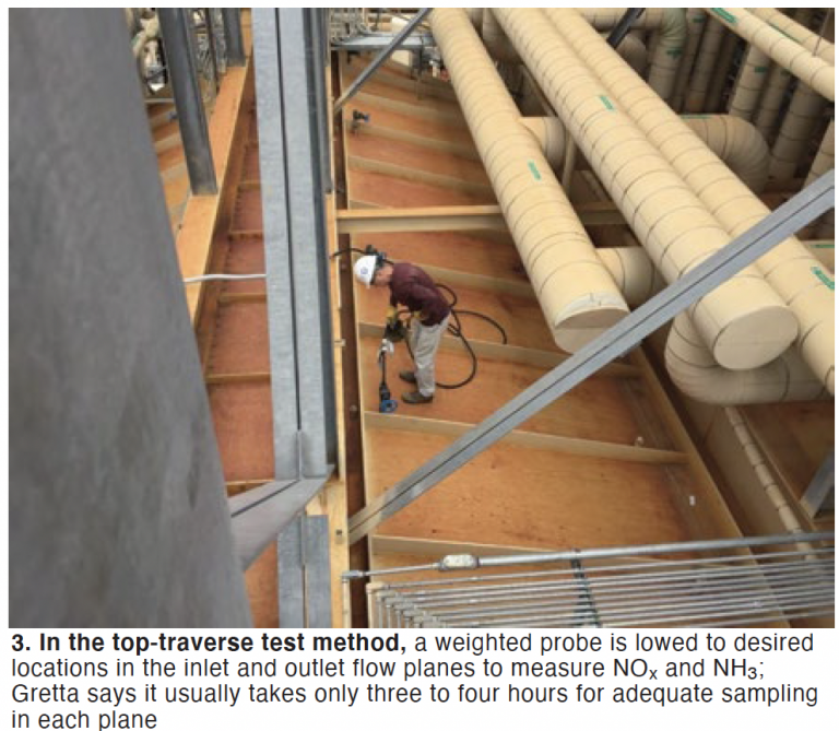
He described a method that makes use of a flexible weighted probe with NOx and NH3 sensors which is lowered into the SCR inlet and exhaust gas flow fields from multiple ports on the roof (Fig 3). Then EPA Test Method 320 is applied. Subsequent CFD analysis revealed the reasons for areas of high and low NH3 concentrations after the ammonia injection grid (AIG).
In the first case study, a 2 × 1 501F-powered combined cycle with close to 500-MW output, this approach resulted in removing and rebuilding the AIG, locating it three feet closer to the CO catalyst, and adding mixing baffles and plates to reduce the root mean square (RMS, an indication of the quality of distribution, the deviation from the average of many values) of ammonia-slip variance from 70% to 10%; additional tuning got it down to 6%. Buildup of ammonium bisulfate in zones of high ammonia slip decreased dramatically.
In the second case study, a 2 × 1 501D-powered combined cycle installed more than 25 years ago had to meet a lower emissions profile, so a dual-function catalyst was selected, but failed to meet the new standards. Analysis showed there was plenty of catalyst, so other system issues were at play.
Gretta and his team simulated 501D exhaust, sampled at 50 data points in a 5 × 10 array of SCR inlet and outlet locations with the weighted probe, and then did an inspection and CFD modeling when an RMS value of 19.3 indicated poor distribution. Causes of poor distribution and solutions were similar to those identified in the first case study.
Insights gleaned from the Q&A included the following:
In both case studies, AIG heavy support elements (which Gretta said probably would be found only in early SCRs) were getting in the way of flow; the replacement was designed to be self-supporting to eliminate the old support structures.
Rust and scale were blocking the AIG ports. The new AIG uses stainless steel instead of carbon-steel pipe and includes cleaning and vacuuming ports in each lance. Hole diameters also were increased and rearranged.
Monitoring NH3 slip for process control may not be practical because the values can be “really different” from what the CEM is reporting to the authorities.
Weld repair clinic particularly valuable to users with limited HRSG experience
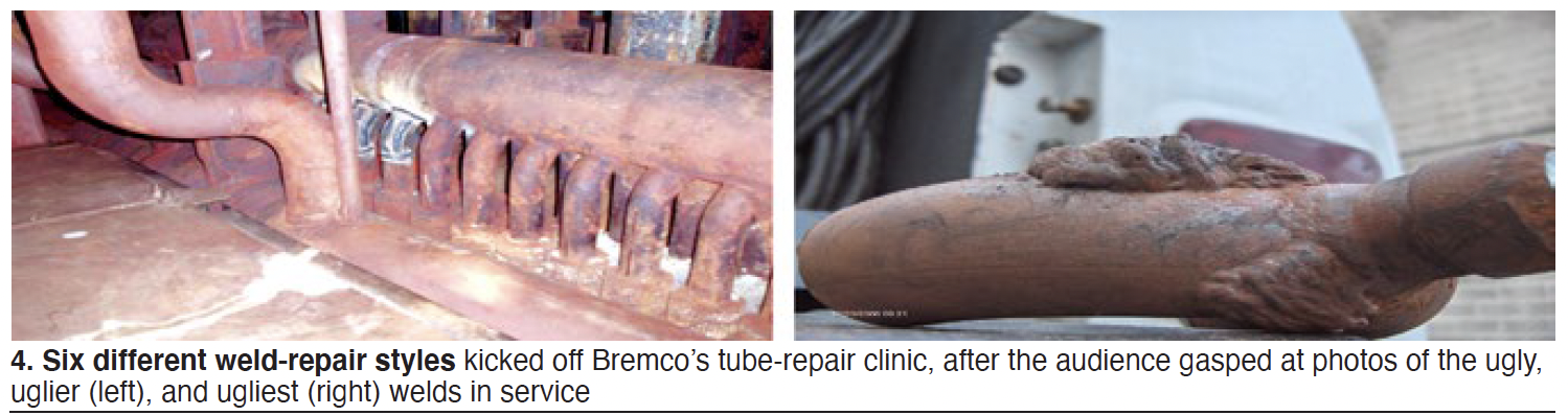
You’ll want to click the QR link to Bill Kitterman’s “Tube Repair Clinic: The Good, the Bad, and the Ugly,” even if just to see the pictures of the “uglier” and the “ugliest” tube-to-header welds (Fig 4). In true photojournalism fashion, Kitterman, head of Bremco Inc, now part of SVI Industries, described six different styles of such welds and the four methods for accessing leaking tubes, including the one fit for an action movie title, “cut your way in, weld your way out.”
Kitterman encouraged the industry to “do more to determine the root causes of tube failures.” He also asked users in the audience to understand that, for repairs of creep-strength-enhanced ferritic tubes (such as P91), the downtime required to do quality work could be longer than they might expect. Welding is the fastest part of the procedure, he noted. Stress relief, code requirements (national, state, and local), official inspections, and insurance-company compliance factors take most of the time.
Example: “Bremco has modified its Alloy 91 weld procedure four times since initial qualification—for pre-heat and post-weld heat treatment and weld-wire requirements.” Proper wrapping to maintain the heat during heat-treat is critical.
Kitterman discussed Weld Method 6, a repair that avoids post-weld heat treatment (PWHT) but is only good for butt welds and on tubes with a wall thickness of less than 0.5 in. “This reduces downtime considerably since PWHT can take up to 14 hours,” he added. He also mentioned Supplement 8 for thicker pressure parts, which also avoids PWHT. It’s good for attemperator piping, although Kitterman conceded that Bremco isn’t yet comfortable with the procedure.
One attendee asked about tube plugging, but Kitterman cautioned that plugging a tube can change the flow patterns. It’s no longer being steam-cooled so the hotter gas can impinge on adjacent tubes, and failures could cascade. Another asked if Bremco undertakes turnkey scope; Kitterman answered yes, but prefers to add third-party specialist heat-treat and inspection companies to the team.
Other questions and responses addressed sonic leak detection methods—all captured in the video recording a couple of clicks away.
With pressure parts, so much depends on high-quality welds. Even if welding “isn’t your thing” at the plant you are responsible for, it’s worth watching this presentation to gain a cursory understanding of what’s involved.
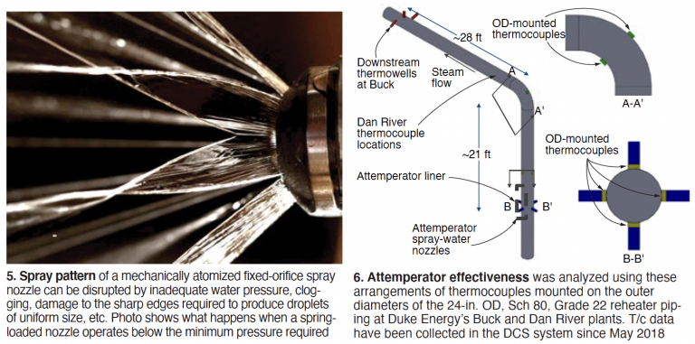
Novel attemperator for reheater circuits eliminates legacy issues
Since virtually everyone at a cycling plant faces issues with their attemperators (Fig 5), you’ll probably want to know about a unique design retrofitted to several Duke Energy combined cycles, one that uses the existing spray ring.
Key to the design is use of HP steam to provide the energy to atomize the spray water (Fig 6). This creates a much finer distribution of droplets, regardless of water flow, pressure drop, or steam velocity in the steam pipe, noted Justin Goodwin, director, Steam Conditioning Group, Emerson Automation Solutions.
Steam-atomized nozzles are not new, but are considered unsuitable for high temperature applications like HRSG attemperators. Emerson reached out to corporate colleagues at Fisher™ to design new steam-atomized nozzles that fit into the existing radial-spray, spring-loaded nozzle ring. 3-D printing the nozzles (patented method) of a hardened cobalt chrome alloy (similar to Alloy 6) eliminated the many weld joints, and failure points inside the nozzles of a conventional steam-atomized unit.
“There are no droplets [of water] falling because they are so fine, which avoids the common attemperator failure mode of water impingement leading to damage on internal pipe surfaces. Plus, the design is highly resistant to plugging and corrosion,” Goodwin stressed. A tap at the h-p drum serves as the source of steam.
Note that the design is not applicable to the HP attemperator, only the reheater units. But good news for designers of new HRSGs: Smaller droplets can lead to a 30-40% reduction in piping lengths.
Lessons learned during the field trial are that a 1 in. to 2 in. connection in the atomizing steam supply piping was a choke point, as was use of a Y-pattern valve instead of a full-bore ball valve (a pressure transmitter was added to troubleshoot these issues). Modified control logic design is critical to a successful retrofit. In response to a question, the presenters noted that they replaced the water temperature control valve, but not the block valve.
Eugene Eagle, HRSG engineer, Duke Energy, and Goodwin’s co-author, said that Duke was pleased enough with the initial field trial on one unit at the utility’s Buck Combined Cycle Plant that they installed the new design at Dan River Generating Station on four additional units. The attemperator with the longest service life had 18 months of operating experience at around 85-90% capacity factor at the time of the presentation.
Duke has eliminated several failure modes, as well as the two-year inspection and test schedule for the previous spring-loaded nozzles, and is in the process of determining the cycle life for the new design. Current thinking is that the nozzles could warrant replacement every three years and that the internal piping liner should be borescope-inspected every two years. Thermal fatigue is the expected nozzle failure mode.
Many of the other questions addressed aspects of the control system (such as the operation of the block valve with the control valve), leakage at the block valve (you need a good block valve and trust it to be tight), the potential need for a second block valve, and possible issues with wet steam in the atomizing steam piping. CCJ