


Compiled by Clyde V Maughan, IEEE Fellow, Maughan Generator Consultants
Generator Users Group (GUG), today organized under the Power Users Group umbrella, was conducted in parallel with the annual meetings of the Combined Cycle Users Group (CCUG) and Steam Turbine Users Group (STUG) in San Antonio, Aug 22-25, 2016.
Recall that the GUG was launched in late 2015—a collaborative industry effort initiated by IEEE Fellow Clyde V Maughan, president, Maughan Generator Consultants, with major support from NV Energy, which hosted the first meeting at its Beltway Complex and Conference, and Duke Energy. The steering committee formed to assure success, chaired by Duke’s Kent Smith, continues to guide the group. (sidebar).
CCJ’s coverage of GUG’s second annual meeting focuses on three general subject areas:
- Stators.
- Rotors.
- Testing and general.
Topics of particularly high interest in today’s powerplants included the following:
- Widespread partial discharge (PD) damage on modern stator windings.
- PD damage and winding failure of global vacuum pressure impregnated stator (GVPI) windings.
- Problems related to severe cracking of rotor forgings.
- Rotor-winding fatigue cracking and thermal sensitivity issues.
- Challenges associated with the operation and maintenance of modern excitation systems.
- Catastrophic failures associated with inadequate ground protection relaying on stator and/or field windings.
- Problems associated with deficient operation and maintenance of water-cooled stator-winding cooling systems.
- Potentially catastrophic dangers associated with inadequate operation and maintenance of generator hydrogen cooling systems.
Two points to keep in mind as you read through this material:
- 1. The GUG’s mission is to provide a forum for owner/operators of electric generators at coal-fired, nuclear, and combined- and simple-cycle gas-turbine plants to share experiences, best practices, and lessons learned on design, installation, O&M, and uprate/upgrade. Expected outcomes are improved safety, maintainability, availability/reliability, and efficiency, as well as the transfer of industry knowledge from experienced engineers to those wanting to gain hands-on know-how.
Although CCJ focuses on gas-turbine users, the editors suggest you not bypass the few summaries of nuclear and coal-fired plant experiences incorporated by Maughan because they offer valuable lessons learned to all generator users.
- 2. Several of the user presentations summarized here were made by members of the steering committee, illustrating the depth of knowledge of the GUG leadership and the value of participation in this annual meeting. Follow the www.genusers.org website for details on the 2017 meeting at the end of August as they are made available; first posting is expected in April.
Users wanting to dig deeper into presentation topics can access the PowerPoints of interest on the Power Users website. Bear in mind that the presentations are available only to users and you must be registered to access them via the User Forum/Conference Archives button in the horizontal toolbar at the top of the home page. Registration is a simple process if you’re not already signed up.
Stators
Stator rewind
As built, McGuire Nuclear Station was equipped with two 1450-MVA, 4-pole generators. featuring water-cooled stators. Within five years of COD in December 1981, both units had been de-rated by about 140 MVA because of operating problems that included end-iron overheating.
There have been numerous maintenance events over the years, including these:
- Stator rewedged in 1998.
- Field rewound in 2007 because of shorted turns and thermal sensitivity.
- Increased oxide fouling in the stator bars.
- Three chemical cleanings conducted in a 10-year period.
- Cracking of aluminum shields in the main lead box.
- Three elevated EL CID indications of about 170 mA each that were slowly increasing between inspections.
A life-extension study was performed in 2010 and it was decided to reuse the generator fields on both units because they had been rewound recently. Relative to the two stators, engineers decided to do the following:
- Purchase a replacement stator with the winding designed for 1550 MVA.
- Convert parallel rings from hydrogen- to water-cooled.
- Upgrade the stator cooling-water (SCW) system to include alkalizer injection for controling pH to address oxide fouling problems.
- Replace the HV bushings with 1550-MVA capability.
After installing the new stator on one unit, the old stator was shipped to the OEM’s factory and rewound with upgrades for use in the other generator.
Site acceptance tests of the new stator included ultrasonic measurement of flow in stator cooling-water hoses, EL CID testing of core, and DC hipot. During the site acceptance test the EL CID test failed, with readings as high as 169 mA detected. A loop test conducted to validate EL CID readings was terminated within three minutes because it failed to meet test temperature criteria. Core repairs on the new generator were required.
Numerous problems were identified with the hose water flow on the SCW system, including near-stagnant flow in six parallel rings. The latter is particularly important in that immediate gross overheating of the rings likely would be accompanied by complete winding failure. Corrections of the hose problems identified were complicated and expensive in dollars and outage time.
Dave Fischli is the generator program manager for Duke Energy’s fossil generation fleet
EL CID versus rated-flux testing
The generator discussed in this presentation, which offers interpretation and correlation of EL CID results to rated-flux testing, is a nominal 400-MVA, hydrogen direct-water-cooled unit which was installed in a coal-fired plant (COD 1980).
The stator was fully rewound in 2004, during which time a significant core fault (287-mA peak value) was discovered by EL CID test after the new winding was installed. Subsequent rated-flux testing and progressive EL CID flux testing confirmed the concern. Part of the winding was removed and a slot-bottom section repaired (with no root cause determined). After repairs, the core was left with EL CID 65-mA peak.
Top-tooth burning and progressive thermal artifacts have been monitored during subsequent inspections with hot spots greater than 10 deg C noted; however, no EL CID readings exceeded 100 mA. The conditions on this core prompted the following questions:
- Does trending the EL CID results offer meaningful condition trending information?
- Do the EL CID results correlate to the rated-flux test results?
- Investigations were conducted to answer these questions, with results discussed by the presenter.
After digitizing select EL CID readings, early minor EL CID indications were corrected to rated-flux hot-spot data with the following mixed results:
- In most cases, EL CID signature correlates to areas where a hot spot exists, but not always.
- Both tests have inconsistencies in results across time periods.
- EL CID was judged “more repeatable,” provided the same excitation is used.
- More-frequent EL CID testing is preferred over less-frequent rated-flux testing.
Comparisons were made of various data: pre-rewind, post winding removal, post high-flux testing, and post repair and high-flux test. With adjustments, EL CID historical data were fairly consistent for trending progressive degradation of the core. Attempts were made to correlate high-flux and EL CID data, with mixed results.
At this point, some fundamental questions remain—for instance:
- At what EL CID value should additional steps be taken—is a value below 100 mA appropriate in some cases?
- Is it possible that rated-flux testing can initiate or advance existing damage deep within the core?
Understanding the detail of core-flux testing remains something of a mystery because results cannot always be taken at face value. It appears there is great opportunity for benefit related to efforts such as discussed by the presenter. For example, he is developing digital tools to facilitate fast and easy trending of EL CID results. These will be shared at a later date and users should find them extremely valuable. An update on progress is likely at the 2017 GUG meeting in Chandler (Phoenix), Ariz, Aug 28-31.
P Eng Ryan Harrison is attached to the ATCO Power central engineering group supporting the company’s fleet of generators and excitation, protection, and distribution systems.
 Issues in hydrogen-cooled machines
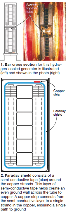
The serious problems discussed in this presentation involved a nine-year-old hydrogen-cooled generator rated 193 MVA, 13.8 kV. Its bar design is shown in Fig 1. During a routine maintenance outage, engineers found all the tube-to-copper resistance readings satisfactory, generally above 1000 ohms, with the exception of the bottom tube in the top coil, slot 22, which read 81.8 ohms. The ends of this tube were cleaned and dried and mica inserted, but the reading did not improve.
OEM guidelines were the following:
- Less than 500 ohms, investigate.
- Less than 100 ohms, change the affected bar.
Further investigations—including the removal of series blocking and groundwall insulation—did not reveal the cause of low resistance or improve the low value. The bar was removed from the winding and sent to a non-OEM laboratory for investigation. No additional understanding was found by the initial investigations. Electrical tests revealed the short likely was located from 7% to 10% of the way from the exciter end. Stripping of the groundwall revealed severe localized overheating locations.
After disconnecting the copper grounding strip shown in Fig 2, the tube-to-copper resistance value increased to more than 50 Mohms. This is a complex bar cross section, not well understood. It is clear that the low resistance values were caused by gross overheating, burning (which resulted from circulating currents caused by a short between the copper strip and a strand), and the resulting carbonization of insulation components. However, the root cause of the short remains unknown.
Leopoldo Duque Balderas has many years of powerplant O&M and engineering experience
Continuous EMI monitoring
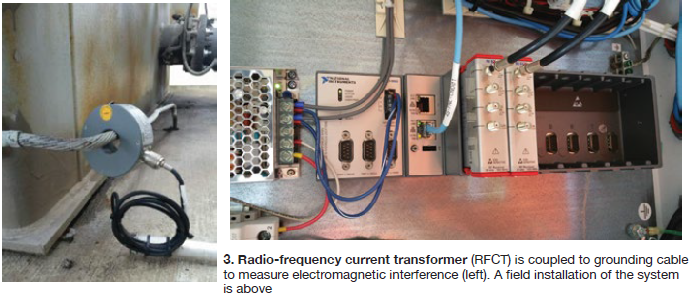
Motors, generators, transformers, and switchgears typically are monitored with hand-held instrumentation. One informal survey found about half of the nation’s powerplants use portable EMI (electromagnetic interference) monitors. EMI also can be tracked with a radio-frequency current transformer (RFCT) placed, for example, on the generator grounding cable (Fig 3).
The speaker told generator users that a new input card had been developed by National Instruments to monitor continuously the output from the RFCT. Duke Energy currently has this instrumentation on 72 transformers and 53 generators at 15 sites. Capabilities of the diagnostic equipment were said to be considerable: full-spectrum scan, live-frequency visual, live-frequency audio, historical-spectrum viewing, power-spectrum trending—five bands with remote access from anywhere on the Duke Intranet.
Fig 4 compares two full-spectrum plots of sister units. The red trace is for a unit that had significant vibration problems, with multiple plant trips from secondary CT wiring being cut. The CT wiring has been stabilized but this trace still shows significant electrical activity. The blue trace is the sister unit at the same location and reveals no signs of any major issues.
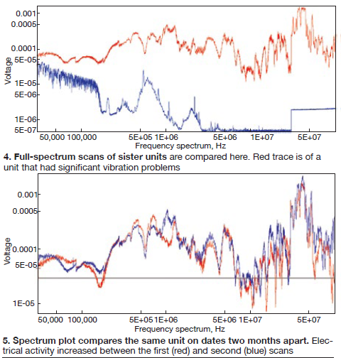
The full-spectrum plot in Fig 5 compares scans of the same unit taken approximately two months apart. It shows electrical activity increased slightly over time. The fact that there is significant activity in the high-frequency areas leads engineers to believe there’s also significant electrical activity near the isolated phase bus (IPB).
In addition to the full-spectrum scan, plant personnel took local measurements with an EMI “sniffer.” It also indicated significant electrical activity in the IPB area. Local measurements show high EMI levels in the bushing-to-bus transition area, as well as in the potential-transformer area. Plans are in place to inspect these areas during the spring 2017 outage.
The diagnostic systems discussed were said to provide plant personnel valuable equipment condition information; interpretation of this information will become better as more experience is gained.
Kent Smith, a 35-yr utility veteran, is manager of generator engineering for Duke Energy
Connection-ring vibration monitoring system
Intermountain Power Project (IPP) went online in 1986/1987 with two hydrogen-cooled generators rated 991 MVA, 26 kV. By the 1990s, leaks had started in the generator windings and both units usually failed leak tests after 1994. A global strand header repair was performed on Unit 2 in 1996 and on Unit 1 in 1997. Leaks continued even after the epoxy repair, with the leaks usually found at joints in the connection rings (Fig 6).
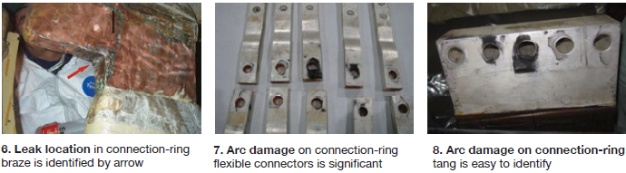
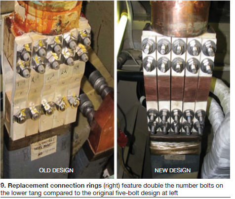
Plant management decided to rewind both generators, including replacement of the connection rings and use of the OEM’s new vertical strand header braze procedure. Unit 2 was rewound in fall 2010, Unit 1 in spring 2011. In December 2011, Unit 1 suffered a massive winding failure, attributed to a failed bolted joint in the neutral connections in the dome. (A similar joint that had not failed is shown in Fig 9.)
Immediately after Unit 1 failed, Unit 2 was taken offline. The flexible connections were examined and arc indications found after only six months of service (Figs 7, 8). The replacement connection rings included additional bolts on the lower tang (Fig 9). But the root cause of Unit-2 arc indications and of Unit 1 failure was use of improper bolting techniques for the stainless steel bolts.
IPP personnel remained concerned with whether the problem had been fixed—in particular because there was no advance warning for the failure. The OEM recommended installation of fiberoptic vibration probes and this was done in January 2012; vibration started to increase in January 2013. Analysis and interpretation of data gathered have not provided definitive results— partially because of little industry experience on connection-ring terminals; plus, weak technical support.
A second vibration probe system has been installed on Unit 1 and a second system will be installed on Unit 2. The trends of the second systems will be compared with the output from the present probes.
Mike Nuttall is assistant superintendent of technical services at IPP
Stator ground in a GE 390H generator
The subject generator is connected to the steam turbine serving a large F-class combined cycle. Plant began commercial operation in 2004 and ran reliably until 2014, accumulating nearly 45,000 operating hours and 1000 starts. During a startup in fall 2014, the unit tripped on volts/hertz and ground relays.
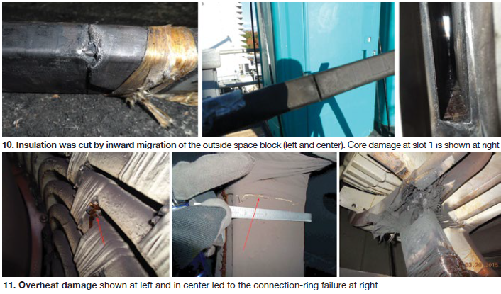
Visual inspection of the external components revealed no problems, but A phase was grounded. This is a three-circuit winding, and two of the three circuits were grounded. The OEM recommended a full rewind, and each bar was checked using a Megger™ before being removed. The bottom bar in slot 1 was found grounded, with its insulation heavily cut by outside space block (OSSB) migration inward.
Many other bars showed damage from OSSB movement (left and center photos in Fig 10). The core damage at slot 1 is shown in the right-hand photo. Burning is much greater than would be expected from the >5 amps of a single ground and probably resulted from core lamination shorting.
The repairs performed included loosening belly bands, rounding the corner of the compression ring (flange), replacing OSSBs one at a time, adding a punching with master bond coating, reinstalling the compression ring, compressing the core to a higher level (2000 ft-lb increased to 2500), retightening of the belly bands, and rewinding the generator with all-new bars.
Overheating phase-to-phase failure
The subject 300-MVA, 18-kV generator was manufactured in 2000 and installed in a combined-cycle plant. On Feb 27, 2015, the plant was removed from service to upgrade the steam turbine/generator’s DCS. The change involved converting from the steamer OEM’s DCS to one installed by a different OEM on the gas turbines.
The plant returned to service Mar 16 at 10:10 a.m. Six hours later, the steam turbine tripped on relays 27, 86-1, and 87G. Both gas turbines tripped as well. The initial walk-down of the steamer revealed smoke coming out of the exciter-end generator bearing cavity; the generator frame was too hot to touch anywhere. Data analysis revealed a peak instantaneous fault current of 74 kA.
Generator cooling-water flow was controlled with a throttle valve; the throttle-valve’s position was controlled by logic, with inputs from stator hot-gas RTDs. The hot-gas RTDs were accidentally configured as “J”-type thermocouples at the ADC signal processing card during the DCS upgrade, so the “measured” temperature never exceeded 80F, thus leaving the valve throttled “off.” Back calculated, the generator gas temperature actually had reached an estimated 415F.
The DCS malfunction caused gross overheating of the generator. Damage was severe during the four-hour operating period (Fig 11, left and center), which led to the connection-ring failure shown at the right in the photo array.
Copper splices were applied to the connection ring and phase dropper, and were reinsulated locally. The stator and coolers were thoroughly cleaned and stator endwindings were treated with wicking resin. The core was requalified by both EL CID and loop/ring testing. The rotor exterior was cleaned.
The unit returned to service May 2. A stator rewind kit, purchased as a contingency, will be installed on a planned basis at the next turbine major outage—or sooner.
Craig Spencer, director of outage services for Calpine Corp’s generator fleet, oversees maintenance for over 230 machines in 20 unique frame sizes from 13 different OEMs
Endwinding vibration
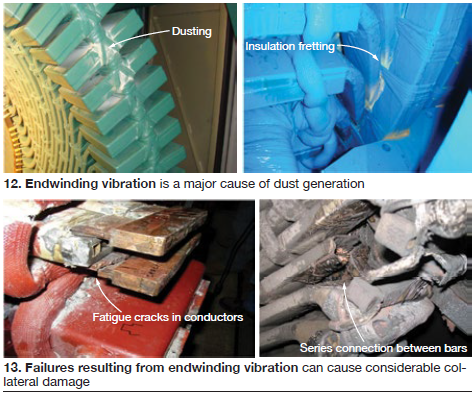
Endwinding vibrational forces and duties have increased as generator ratings have increased and as more compact designs have evolved. Simultaneously, cost reductions for less robust designs have tended toward more vibration problems. Examples of dust generation from vibration are shown in Fig 12. Note that endwinding vibration has been found to have the highest total loss mitigation value on recent common generator failures. If not detected before failure, considerable collateral damage may occur (Fig 13).
Two common ways are used to assess vibrational issues:
- Periodic visual inspection looking for evidence (dusting, fretting, greasing).
- Periodic impact (bump) testing to identify natural frequencies and ensure they are not causing resonance.
Because each of these alternatives requires an outage, there has been a trend toward installing endwinding vibration detectors (fiberoptic non-metallic accelerometers) on units with suspected or known vibration issues. Sensors are installed in locations where high vibration is most likely. Displacement values are commonly read, but velocity/acceleration values may provide better analytical information. Displacement under 5 mils is usually considered safe, with 10 mils cause for concern and 20 mils considered dangerous.
The bottom line: Endwinding vibration monitoring systems can be a valuable resource on suspect windings to provide early warning and allow optimum scheduling and planning of needed repairs.
Mladen Sasic has dedicated most of his career to instrumentation for generator condition monitoring—in particular, core lamination insulation testing and wedge-tightness assessment
Stator global VPI technology
Siemens presented an overview of its generators using global vacuum pressure impregnation (GVPI)—including operating experience and repair options. The company introduced its GVPI system in 1988 and today has more than 1650 such stator windings in service with a total capability of 239,000 MVA. Thus far, these machines have combined for more than 25-million operating hours and 320,000 start/stop cycles—in round numbers. The units employ indirect-air, indirect-hydrogen, and water cooling. Voltage ratings extend to 22 kV, outputs to 870 MVA.
Design features of the GVPI insulation system for a stator bar are highlighted in Fig 14. The insulation ground-wall materials are applied over the copper in the following sequence: inner corona protection, ground-wall insulation, inner-outer corona protection, mica splitting layer interspersed with contact tape, and outer-outer corona protection layer.
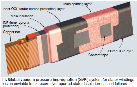
The speaker said that, to date, there has been no report of a stator-bar failure attributed to this insulation system. GVPI windings, he continued, do not require re-wedging, re-tightening of enwinding structure, or re-tightening of the laminated core—for the entire lifecycle of the generator, with a reliability factor of greater than 99.9%.
Damage to GVPI stator windings is very unlikely, and when it occurs, the cause typically is impact by a foreign object. Should such damage occur, the OEM has repair procedures to suit both the situation and customer preferences.
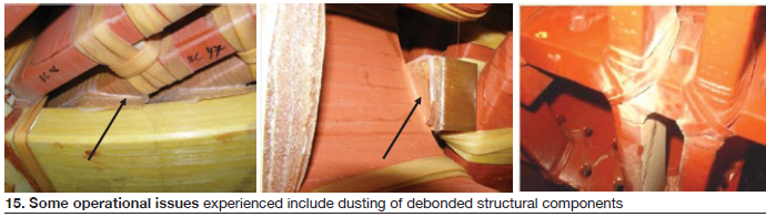
Some operational issues that have been experienced include dusting of de-bonded structural components, which may occur at any bonded interface in the end winding (Fig 15). Also, stator endwinding natural frequencies may experience a shift over time and if they approach the driving frequency, loosening will be accelerated. This condition can be addressed by adding tangential blocking between the top-layer bar ends near the series connections.
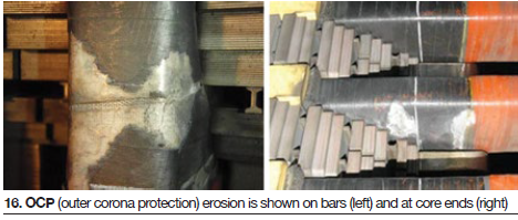
Localized erosion of outer corona protection has been found on several units at the ends of the core (Fig 16). Methods have been developed for the repair of such findings.
Scott Robinson has global responsibility for Siemens’ generator service business—including R&D, management of technical issues, product development, customer satisfaction
Rotors (fields)
Field ground indications
Grounds in two different excitation systems were discussed by John Demcko, who has an exceptionally broad and deep background in power generation equipment: those with brushless excitation systems and those with collector rings and brushes. The two case studies presented illustrated the challenging complexity of excitation-system diagnostics and maintenance. When we speak of a field ground, the speaker said, what we really mean is an excitation system ground.
The first ground considered was on a brushless system. In spring 2006, a modern brushless field ground detection system, Accumetrics Inc’s earth fault resistance monitor (EFREM), was installed on Combined Cycle Unit 4 at the company’s West Phoenix Generating Station (Fig 17). It replaced an OEM system that never worked properly.
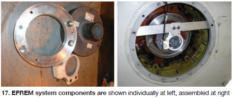
With the Accumetrics system, the field resistance to ground is monitored offline, as well as online, and is telemetered to the plant DCS. Six months after installation, the field ground alarm came in solid while the unit was offline. Since the alarm occurred during heavy rain, engineers decided to dry the system before drawing any conclusions. In 3.5 hours, resistance increased from 12 kohms to 20 Mohms. Better waterproofing and caulking of possible water ingress points thus far has been effective in mitigating the issue.
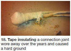 The second ground was on a collector/brush system. During a normal startup, generator voltage did not build up to nominal rated value. Investigation provided some startling information. First, the field itself had a ground. But there was a station-battery ground as well. The combination of the two grounds allowed part of the field excitation current to bypass a portion of the field turns.
While the field was being rewound, resolution of the station-battery ground was pursued. It was found at a taped connection joint left lying on the steel-deck floor (Fig 18). Over many years, the taped insulation had worn away, resulting in a hard ground.
John Demcko is a senior consulting engineer in Arizona Public Service Co’s Technical Projects Engineering Dept
Experience with Alstom air-cooled generators, Part I
System-wide, Southern Company has seven Alstom air-cooled generators rated 313 MVA, 21 kV. There have been significant maintenance and operational issues on these units, including the following:
- Stator phase-connection conductor fatigue.
- Stator endwinding voltage grading deterioration.
- Stator spring-plate fatigue.
- Stator side-filler migration.
- Stator frame plate weld failure.
- Field retaining-ring insulation deformation.
- Field slot-liner cracking risk.
- Field-winding pole-connector fatigue.
Only the last was discussed in this presentation.
Initial awareness of the problem came in April 2012 coincidental with the follow-up inspection of a phase-bar blocking modification. Prior fleet-wide inspections offered no clear evidence of pole-connector fatigue. But review of previous inspection photos with a focus on the probable crack-initiation areas showed signs of possible initiation (upset metal).
Follow-up inspections over the last four years have shown all previous “possible initiation” sites to have definitive cracks with propagation in progress. Photos shared to illustrate the problem included those here labeled Figs 19-24.
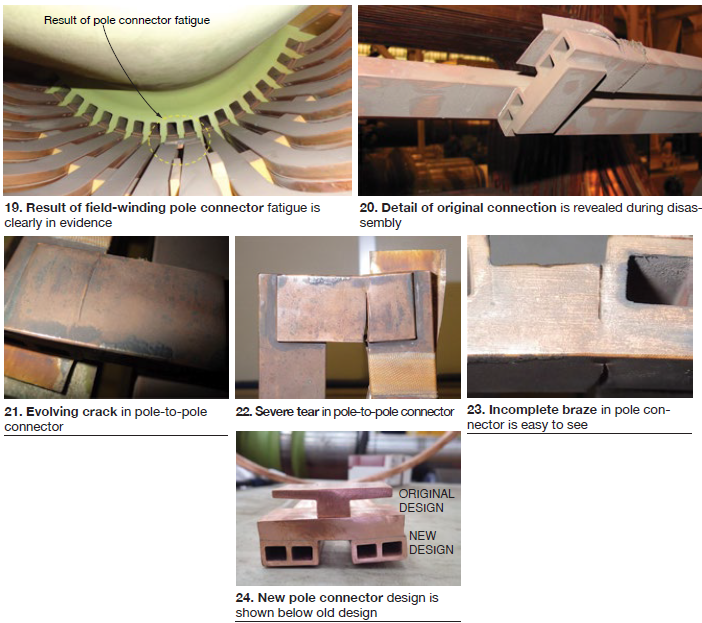
Inspections in April 2013, April 2014, and July 2014 on the unit with most advanced fatigue condition revealed continuing crack propagation on both pole (redundant) connectors. Repair was implemented in December 2014.
Engineers concluded there is a definitive correlation to start/stop cycles. Inspection data show the rate of crack propagation to have some consistency for a given pole connector but it clearly varies from one connector to another. It is expected that pole-connector replacement eventually will be required on all seven generators.
Jeff Phelps, principal engineer, supports Southern Company’s generator fleet
Alstom generators, Part II
Initial awareness of the phase-connection issue discussed by the speaker came in August 2010 following a stator-winding in-service failure. Root cause: phase-bar resonance. The failed unit was repaired and returned to service.
An aggressive plan implemented for the company’s seven air-cooled generators of the type described focused on inspection and repair of “at risk” units (see report segment immediately above). It called for repairing damaged strands (where necessary) and improving the support blocking scheme at phase bars. The blocking-scheme mod has evolved and periodic maintenance is anticipated, including periodic natural-frequency testing. A monitoring program is in place to avoid a repeat failure event.
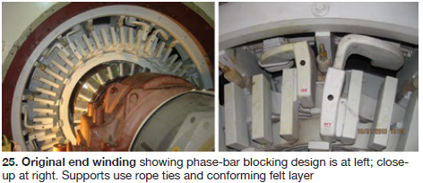
A winding in satisfactory condition is shown in Fig 25 (left). A close-up of the area is alongside. The failed joint is shown in Fig 26. The extensive burn damage resulted from the arc which continued to carry current for several seconds after ground relay trip as the field current decayed.
Fig 27 (left) revealed cracked strands (at the tip of the pen), which are shown close-up at the right. The photo in Fig 28 is of the repaired connection with additional blocking and tying.
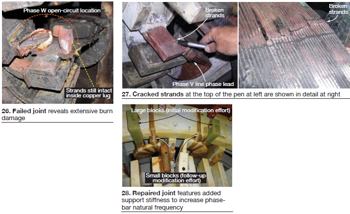
The Alstom design places a resistance temperature detector (RTD) in each of the 12 phase-lead slots. Operational data show that the RTDs in slots with many cracked strands clearly exhibited a higher temperature rise than all remaining RTDs prior to cracked-strand repair. Data mined following the repairs show the temperature rise of each RTD returned to values consistent with the overall average of all 12 stator RTDs. Thus careful attention to RTD readings offers an opportunity to remove a unit from service before winding failure.
Jeff Phelps, principal engineer, supports Southern Company’s generator fleet
Excitation failure
Unit 4 at Handley Generating Station is an Allis Chalmers hydrogen- and water-cooled generator with brushless excitation. It went into service in 1976 and is used today primarily in peaking service. The main exciter is rated at 600 V/4500 amps. Conversion to DC is accomplished through a rotating 3-phase rectifier comprised of inboard and outboard diode wheels, each with eight fuses, eight heat sinks, and 16 diodes per phase.
Handley 4 was called upon to perform a required reactive capability test which dictates unit operation at maximum megawatt output and at maximum lagging MVArs for 15 minutes. The test was to be completed under a recently developed procedure for reactive capability testing. During ramp-up from no-load, the generator briefly exceeded the published maximum excitation limit. It was quickly brought back within the machine capability curve.
The MVAr output was above historical levels, but all generator parameters were acceptable and within manufacturer limits. Approximately 12 minutes into the test, the over-excitation limiter and instantaneous limiter alarms were received and the unit tripped from service.
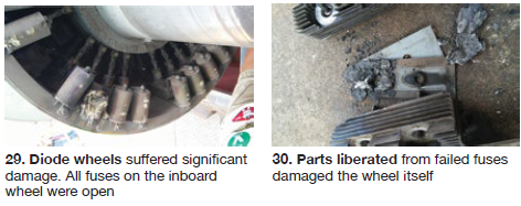
Subsequent investigations identified significant damage to the diode wheels. All fuses on the inboard wheel were found open. Severe damage was noted on two of the diodes.Both of these fuses were associated with the same phase and had completely blown apart (Fig 29).
Parts from the failed fuses were ejected, damaging remaining components in the wheel as well as the wheel itself (Fig 30). Severe heating and arcing damage was noted on two heat sinks and their associated insulation.
Repairs required complete disassembly of both the inboard and outboard diode wheels.All fuses and diodes were replaced, damage to the inboard wheel was repaired and NDE tested, and heat-sink insulation and the two damaged heat sinks were replaced.
During the repair process, components of the undamaged outboard diode wheel were electrically tested. A large number of fuses were found open-circuited—including five out of eight fuses on one phase. Although each of these fuses is equipped with a fuse-failure pop-up indicator, none of the indicators activated. (Pop-up indicators only activate if the fuse fails electrically.) The owner’s engineers concluded that fatigue failure of the fuse elements caused the open circuits. Periodic testing of fuses is necessary to ensure their integrity.
Further investigations concluded that only two of eight fuses were in service on one phase at the time of the failure. This caused overloading of the two circuits, and subsequent overheating of two heat sinks. The insulation under the heat sinks burned and allowed electrical tracking and a phase-to-phase fault in the inboard diode wheel. The surge in fault current caused the two remaining fuses to blow apart, and the unit tripped from service.
Actions to prevent future incidents include daily inspections of the diode wheel, increased testing of diode-wheel components, revision to fleet reactive capability test procedures, and improved operator training.
Joe Riebau, senior manager of electrical engineering at Exelon Power, has more than three decades of experience in the testing and maintenance of powerplant electrical equipment
Emergency field rewind
Numerous maintenance problems with generators in the Duke system were described with slides narrated by the utility’s Fred King and AGTServices Inc’s Jamie Clark (access the presentation for more excellent photography). Issues included broken J-straps (Fig 31). On another unit, a flux-probe test revealed shorted turns in a large coil. Inspection revealed the root cause as movement of turn insulation (Fig 32).
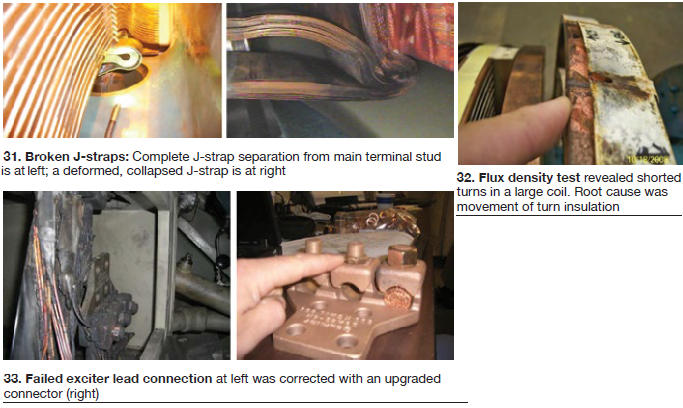
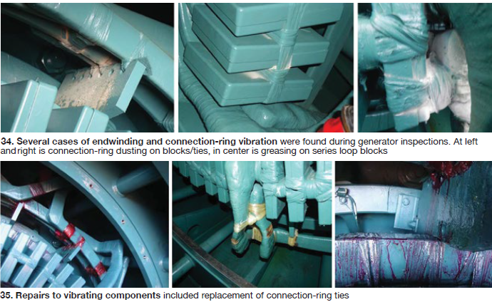
Failure of an exciter lead is shown in Fig 33 (left) with the upgraded connector to its right. Several cases of endwinding and connection-ring vibration have been experienced by Duke generators with indications as seen in Fig 34. Each of these was corrected by tie replacement and/or application of bonding resin (Fig 35).
Answers to several informal industry survey questions were provided by the presenters for everyone’s benefit. The percentages of “yes” responses follow the questions below:
- Have you experienced J-strap failures? 50%
- Do you require a pressure test on bore seals on hydrogen-cooled units? 89%
- Have you found field slot-liner problems requiring field rewind? 53%
- Have you operated a unit with one field ground? 47%
- Do you require new copper for field rewinds? 5%
- Do you require a high-speed balance after field rewind? 70%
- Do you specify stator wedge materials for rewedge/rewind projects? 53%
Fred King is a senior generator specialist with more than three decades of electrical experience at Duke; Jamie Clark is AGTServices’ sales manager
Generator end-plate indications
The Altamira II combined-cycle plant was notified in October 2014 of some findings in the generator-rotor end plates that had occurred at other Mexican plants with similar air-cooled generators. Two months later, inspections at Altamira II revealed several cracks on the rotor end plates for its two gas turbines and steam turbine (Figs 36 and 37).
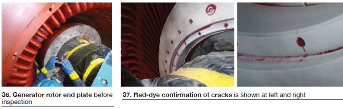
The OEM strongly recommended not running the units in this condition because of the risk of catastrophic failure. Before restart, the OEM recommended replacing the rotor end plates at both ends of all three fields. Removal of the retaining rings would be required to do this, and based on the OEM’s experience, destructive removal was likely. To avoid destructive removal of the retaining rings (spares availability was a major concern), the end plates were removed destructively, without touching the retaining ring.
Root cause of this fleet problem was stress corrosion cracking. Recommended preventive action included replacement end plates made of an improved material, application of anti-corrosive paint on the end plates, and the elimination of tapped holes for the rotor baffle assembly around the inter-pole center (the lower set of holes, most easily seen in the center photo).
Eliezer Garza Ortiz, an electrical engineer with an MBA, is the director of Altamira II
Damaged steel: Mechanisms and symptoms
Neil Kilpatrick’s presentation was an hour-long lecture/discussion tutorial covering the following topics:
- General machine construction.
- Damage mechanisms in steel, for non-metallurgists.
- Where different damage mechanisms sometimes are identified.
- Observable symptoms that might be present, with comments on symptom severity.
This tutorial focused on the generator rotor. Topics included, among others: damper current damage, electrical joint failure, fretting, deposition of decomposition products on visible rotor surfaces, overheating of retaining rings and other forgings, and stationary/rotating rub damage. Material presented on the last topic is summarized below to offer perspective on the depth of coverage and the value of participation in GUG meetings.
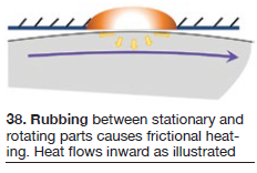
Stationary rotating rub failure sequence (refer to Fig 38):
- 1. Contact is established and maintained. Frictional heating occurs over the contact surface and heat flows into both contact elements.
- 2. A heat-source zone is established. The heat-input plane is the contact area at the interface.
- 3. Heat flows inward and along the surface.
- 4. The temperature rise depends on the amount of energy input and the time rate of input.
- 5. As temperature builds in the hot zone, the metal tries to expand, but the cold surrounding metal is much stronger and more stable and compressional yielding occurs. Increasing hot-zone peak temperature means more compressional yielding; as temperature increases, expansion increases, and strength drops.
- 6. This kind of rub can result in local metal temperatures in excess of 1300F, with metallurgical transformation to austenite.
- 7. Some hot metal will be “smeared” by adhesive interaction.
- 8. When rubbing stops, the hot zone effectively is quenched to the surrounding metal temperature. In typical magnetic rotor steel components, this means that a hardening transformation occurs. But, at the same time, a significant contraction of the former hot zone occurs, and the stress state of transformed metal zone will change to what can be a very high tensile stress.
- 9. The result is a zone of metal with high tensile stress, additive to normal operating stress, and with a ductility and toughness which tends to be very poor.
- 10. Intensity of damage tends to correlate with the local volume of damaged metal; high volume relates to more severe damage with increased cracking tendencies.
- 11. Crack initiation and propagation cannot be predicted, but, clearly, the probability of cracking must be significant.
- 12. This condition means that the part (rotor forging, blower hub, blower blade, etc) is now capable of erratic and unpredictable behavior.
Unless this is a superficial condition, repair/replacement likely will be required.
Metallurgical problems are widespread on generators and additional topics include these: braze-joint failure processes, torsional fatigue symptoms and analysis, general rotor overheating symptoms and analysis, coupling-bolt failure modes and analysis, and rub-induced bending analysis and repair.
Neil Kilpatrick recently opened his own shop—GenMet LLC—after accumulating more than 45 years of generator metallurgy experience at Westinghouse Electric Corp and Siemens Energy
Field rewinds, etc
This presentation was divided into three segments, with Keith Collins covering field rewinds and high-speed balancing, and Keith Campbell stator insulation. Collins opened the session with a general summary of cooling methods for field windings. But the focus of his presentation was on the merits of reusing copper versus rewinding with new copper (Fig 39).
The steps for a rewind with existing copper are the following:
- Visual inspection of the copper.
- Nondestructive removal and cleaning of copper fit for reuse.
- Visual inspection.
- Repairs, if any.
- Re-annealing and final inspection.
For a new-copper rewind, the steps discussed were these:
- Procure new copper and verify it meets specs, including shape.
- Remove the old winding—destructively if necessary.
- Install the new winding.
The pros and cons of using new copper versus old copper were discussed in detail, with excellent photography illustrating best practices, lessons learned, etc. Much can be learned by accessing the presentation on the user group’s website.
Key takeaways based on MD&A’s experience:
- New copper isn’t required for a field rewind; nearly all damage to existing copper can be repaired by splicing and/or brazing.
- If damage is so bad that the use of new copper is suggested, there probably is a bigger problem at hand—such as forging damage.
- Reverse-engineer coils during rewinds to gather data for future use.
- If new copper is the path taken, be sure it is procured long before the scheduled outage.
Stator insulation. Campbell took over the speaking duties from Collins and listed these five factors as contributors to insulation degradation: time, thermal, mechanical, electrical, and the introduction of contaminants. Various aspects of stator-bar groundwall insulation degradation were considered and illustrated—including mechanical vibration (Fig 40) and electrical phenomena such as partial discharge and vibration sparking.
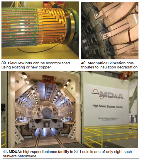
High-speed balance. Collins returned to the front of the room and began his second presentation with a backgrounder on the evolution of balance equipment. He recommended high-speed balancing of generator rotors following a rewind with new or existing copper, after the replacement of a major component, and after any machining. Remainder of the presentation offered details on MD&A’s balance facility in St. Louis (Fig 41), which can handle rotors up to about 90 tons, 13 ft in diameter, and 49 ft long. Plus, is has full high-speed thermal test capability to accommodate electrical testing of the rotor at speed.
Information disseminated at the meeting showed only seven high-speed balance facilities in the country in addition to MD&A’s, with most in the East—Schenectady, NY; Richmond, Va; Pooler, Ga; Columbus, Ohio; Charlotte, NC. The other locations: West Allis, Wisc, and Farmington, NM.
MD&A’s Keith Collins is operations manager of the high-speed balance facility; Keith Campbell is a generator specialist
Generator rotor thermal sensitivity
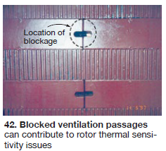
Rotor thermal sensitivity normally can be attributed to one or a combination of the following factors: insufficient or unequal clearances, asymmetrical coil expansion, bound slot wedges, blocked ventilation passages, and shorted turns. Each of the above was discussed in this presentation.
Insufficient or unequal clearances can exist from one coil to another and/or from the coil ends to the steel end plate. This condition can cause forces to be applied that may result in a bending of the rotor forging and increased vibration.
Asymmetrical coil expansion can be caused by restriction of one or more coils and result in unequal coil expansion because of the lack of an adequate slip plane between coils and forgings. This may result in unequal expansion forces on the body forging causing it to bend and vibrate.
 Bound slot wedges often result from deficient wedge design/incorrect installation, resulting in asymmetrical and restricted expansion which can place bending forces on the forging and cause vibration.
Blocked ventilation passages can occur throughout the ventilation circuits with one location mentioned in particular: radial discharge holes (Fig 42).
Shorted turns can have a variety of causes: conductor movement, incorrect blocking issues, conductor restriction leading to ratcheting or distortion, connector issues, foreign material. The location and magnitude of the shorted turns has a significant influence on the level of thermal sensitivity; specifically, the closer the coil with shorted turns is to the pole head the greater the influence of the short.
The presentation also reviewed NEC’s solutions to the thermal sensitivity problems discussed.
W Howard Moudy is National Electric Coil’s director of operations
Testing, general
Oil-intrusion events
Oil-intrusion events are a fact of life at Duke Energy, a large utility with hundreds of generators in service. To learn more about how others in the electric power industry deal with oil intrusion, GUG Chairman Smith and his Duke colleagues conducted an informal survey. More than three-quarters of those surveyed said they have oil-intrusion concerns.
Next question: “What level of oil intrusion do you consider a concern?” Responses varied:
- Less than 10 ml weekly concerned no one.
- Between 10 and 20 ml weekly concerned 26%.
- From 20 ml weekly to 10 ml daily was of concern to 37% of those surveyed.
- From 10 ml to 100 ml daily got 21% of the respondents concerned.
- The remaining 16% were not concerned until intrusion exceeded 100 ml daily.
- Smith next summarized the following recent oil-intrusion events in the Duke fleet:
- Operator error was blamed for the pumping of more than 3000 gal of oil into the generator bushing box on a large water-/hydrogen-cooled machine.
- During startup, the oil detraining tank on a hydrogen-cooled unit was overfilling and the bypass valve had to be manipulated to control tank oil level. When the unit was being removed from service for repair, tank level increased and oil was pushed into the machine.
- A large hydrogen-cooled unit consistently required oil clean-up from the machine’s belly but it had no liquid detector alarms. Although there’s no known impact to date, stator re-wedging will be needed.
- Oil intrusion investigation on a large water-/hydrogen-cooled generator is ongoing. Intrusion was noted during the last rewind; the end-bell mating surfaces were not as flat as expected.
Cleaning was required in each of the four cases cited above. It ranged from minor to extensive and given the complicated internal complexities of the generator, cleaning may never be finished in some cases. Corrective actions, sometimes ineffective or incomplete, can include the following:
- Enlarge flex-seal grooves and add additional pumping locations.
- Re-pump flex seals.
- Machine end bells to achieve better mating surfaces.
- Replace TiteSeal™ compound with Flex Seal®.
- Install drain holes in bushings to drain oil from the cooling path of the bushings.
- Replace seal-ring springs.
- Correct piping deficiencies.
Kent Smith, a 35-yr utility veteran, is manager of generator engineering for Duke Energy
SFC flashover
Mystic Station has eight generating units, six of which are arranged in two separate 2 × 1 combined-cycle blocks. The gas turbines require use of a static frequency converter (SFC) for startup. A precise start-up procedure is followed, one using multiple buses ranging from the 5-kV SFC output circuit to the 16-kV-rated generator bus.
Startup consists of operating the SFC and excitation concurrently to bring the units up to 2400 rpm. The SFC is then switched off and disconnected, and combustion takes the units up to 3600 rpm. Finally, excitation is reapplied near 3600 rpm as the units become ready for synchronization to the grid.
During a troublesome start of one gas turbine, the SFC circuit failed to disconnect from the generator bus. This led to a direct connection between the SFC and generator after 2400 rpm. Then excitation was reapplied at 3600 rpm and voltage increased to 16 kV. The application of 16 kV on the 5-kV-rated SFC circuit led to failure of the SFC and caused multiple cable failures in trays linking the SFC to the generator bus.
A subsequent investigation determined the cause of the event as failure of the SFC disconnect switch to remain open after 2400 rpm. Insufficient noise filtering in the plant DCS and absence of feedback loop between field breaker and SFC disconnect switch position were deemed contributing factors.
Corrective actions implemented consisted of protection logic modification to add interlocks between SFC disconnect switches and field breaker, as well as between the SFC disconnect switches and generator neutral ground disconnect switch. Dead-band filters also were installed in the plant DCS to improve noise filtering, and field-breaker trip logic was modified to achieve faster tripping.
Temporary conduit running from the length of the generator bus to the second plant SFC was installed to reach plant operational availability within one week, but complete repair to original condition took significantly longer and required OEM involvement.
Kapil Inamdar is an engineer on the central engineering staff responsible for providing technical support to Exelon powerplants; Joe Riebau is senior manager of electrical engineering
EMI testing
Condition-based maintenance (CBM) is an important goal in the power generation business. The focus is on preventing in-service failures by maintaining equipment only when needed and identifying where maintenance is not necessary. CBM conserves resources, reduces production costs, and minimizes the possibility of damage during maintenance (such as that caused by a rotor drop).
Electromagnetic interference (EMI) is a powerful tool for condition-based maintenance and is useful in diagnostics of both electrical and mechanical problems in the generator system. It has been used for 80 years to locate defects in power lines that cause radio and television interference. Application to powerplant equipment began in 1980.
EMI signals are collected with a split-core radio-frequency current transformer (RFCT) and radiated energy is measured with a simple hand-held instrument. These two techniques permit detailed condition and location identification. Maintenance recommendations can be given with the first test. Trending of numerous tests is not necessary to analyze data but may be helpful for long-term analysis.
There is no interference with plant operations while taking the EMI readings, which are passive and non-invasive. There is no applied signal and no risk whatsoever to equipment operation. The frequency spectrum is taken with an RFCT, typically applied to the generator neutral or a grounding cable, and the output signature can be analyzed on the screen of your personal computer.
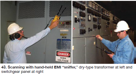
The hand-held instrument measures radiated EMI and is simple to understand and use. In Fig 43 (left), a transformer is scanned for radiated EMI. Switchgear typically can be scanned in a few moments (right). This technique can detect and identify the cubicle where there is deteriorated insulation or loose connections.
Using the RFCT approach, each system defect results in a distinctive radio-frequency spectrum unique to the physical location and type of defect present within that electrical insulation system. More than five-dozen conditions have been identified with this test. Comparison of data collected at two generator loads can determine if loose windings are developing. Substantial basic training is required to interpret the RFCT output curve, and backup interpretation can be obtained from Doble Engineering when interpretation results are uncertain.
Doble’s Paul Spracklen is a rotating-machinery systems expert
Hydrogen safety
Hydrogen is very explosive, colorless, and odorless, as well as difficult to contain. Yet it has been used widely as a coolant for generators since 1938 (today there are over 10,000 hydrogen-cooled generators in service). Hydrogen is used for several reasons:
- Windage/frictional losses are less than for air.
- The relative density of hydrogen is four times less than that of air and its heat-transfer characteristics are better.
- It is 14 times more efficient in removing heat than air.
Compounding the inherent dangers in handling hydrogen, the generator fleet is growing older, auxiliary hydrogen equipment is ageing, outage intervals are increasing, the workforce is getting younger and leaner, and training programs are not what they used to be. Thus the dangers of using hydrogen as a coolant may be increasing.
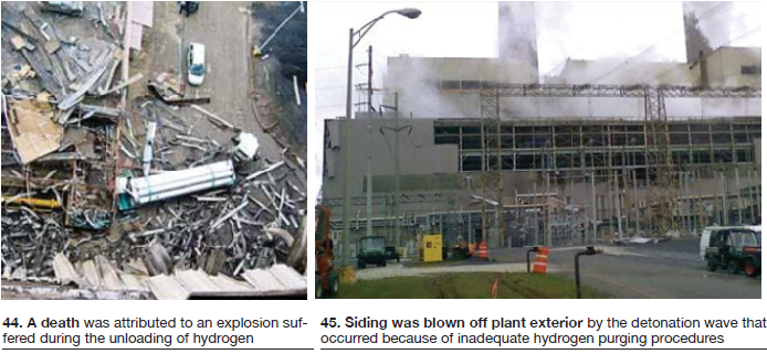
A recent newspaper headline stated: “Deadly explosion at ABS powerplant blamed on hydrogen gas.” Damage caused by recent explosions is shown in Figs 44 and 45. There was a death while unloading hydrogen at the plant in the first photo. The explosion at the second plant occurred because of inadequate hydrogen purging procedures. While there were no deaths at that facility, damage was significant.
It is essential for plant personnel to know and understand the hazards associated with hydrogen and that all equipment for handling and storing this gas be certified and maintained in first-class condition (Figs 46 and 47). Finally, because purging is inherently complicated, and can be dangerous if performed improperly, all personnel involved must be well trained, non-sparking tools (bronze) must be used, carbon dioxide must be readily available in sufficient quantity, appropriate safety signage must be in evidence in critical areas, and keyed lock-outs must be provided for “air” and “hydrogen.”
E/One’s Steve Kilmartin has more than 30 years of generator experience—including time at an OEM and a major engineering company
Generator testing, overhaul
EthosEnergy Group’s (EEG) two-hour session was divided into these three topics:
- Generator deterioration causes and corrective actions.
- Overview of the company’s generator maintenance capabilities.
- Illustration of EEG’s capabilities by review of 16 case studies.
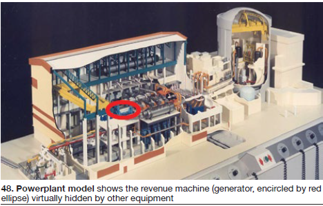
The first slide (Fig 48) illustrated the complexity of a powerplant and the “insignificance” of the generator. While comparatively small in size, the importance and complexity of the generator is hard to over-emphasize. In the figure, the generator is the tiny white object within the red ellipse.
The design life of generators is commonly considered to be about 30 years. Aging considerations include fatigue life of the forgings, stop/start cycles completed, equivalent operating hours remaining, the machine’s position on the “bathtub curve,” rate of increase of component failures, and the point at which plant’s economic feasibility becomes negative.
The four major stresses imposed on the generator were considered individually: electrical, mechanical, thermal, and environmental.
- Electrical stresses listed were core back-iron overheating caused by over-excitation operation, overheating of core ends caused by under-excitation operation, core manufacturing or repair defects, partial-discharge activity, and surface contamination and moisture.
- Mechanical stresses: core looseness, vibration and fretting, stator winding slot looseness and 60-Hz/120-Hz vibration, stator endwinding looseness and vibration, rotor component stresses caused by centrifugal forces, and abrasive material contamination.
- Thermal stresses: core insulation damage, poor ventilation, continuous operation at high temperature or overload, differential expansion between components, and thermal cycling.
- Environmental stresses: water absorption, oil contamination, acidic or alkaloid atmospheres, and carbon dust.
EthosEnergy Group has found that causes of in-service failures have been: 37% bearings, 33% stator windings, 11% unspecified, 6% shaft/coupling, 5% external devices, 5% rotor, and 3% brushes/slip-rings. By contrast, major problems found during inspection/test have been: 61% bearings, 10% unspecified, 8% stator windings, 8% shaft/coupling, 7% brushes/slip-rings, 4% external devices, and 2% rotor.
Test and inspection were discussed briefly. Tests commonly used on stators are: winding copper resistance, insulation resistance and polarization index, EL CID/loop test, partial discharge, insulation tan delta/power factor, and AC/DC hipot.
Tests commonly used on fields are winding copper resistance, insulation resistance and polarization index, repetitive surge oscillography (RSO), pole (and turn) drop, AC/DC HV hipot (on major repairs and rewinds).
Repairs (solutions) were discussed in detail. Topics covered included: stator core restacking, cleaning methods, repair of partial discharge indications, stator wedge testing and replacement, stress corrosion cracking of 18/5 retaining rings, exciter and collector issues, bearing and journal damage. Get the details by accessing the presentation via the Power Users website.
Remainder of the presentation was a detailed description of company capabilities for repairing generators, illustrated by a review of 16 case studies of work performed by EEG repair crews.
Darian Garcia is a project manager and Pawel Kwiatkowski is an applications engineer with EthosEnergy Group
GE presentations
As a major generator manufacturer and supporter of the Generator Users Group, GE had most of the third day of the 2016 user-group conference for discussion of its product line. There were many presentations, several summarized briefly below. The editors suggest following up by reviewing the various GE PowerPoints posted to the Power Users website.
- GE has three general lines of generators: air-cooled, 30-340 MW; hydrogen-cooled, 90-590 MW, and water-cooled, 530-1800 MW. For cost and quality reasons, the company has adopted a modular design philosophy using long-time proven features and components.
- The OEM’s recommendations are detailed in GEK103566, recently updated. GE is migrating towards removal of the first-year inspection requirement, and the latest GEK document focuses more directly on updated recommendations with less-intrusive inspections.
- Generator uprate. This informative presentation discussed the important and not-well-understood generator kilowatt and kilovolt-ampere output issues, and the need for generator modification or replacement to safely support a plant uprate.
- Generator fundamentals. Discussion included interesting sketches that illustrated how and why a generator can convert rotating torque energy from the turbine into electrical power for the grid. Various physical configurations of air- and hydrogen-cooled generators were described with numerous photos. Some of the major generator components were described in detail—including the stator core, stator wedging system, field winding, hydrogen seals, and excitation systems.
- Excitation systems can be challenging components, as illustrated by a listing of 12 different excitations systems for GE and nine for Alstom, which was acquired recently by GE. Brushless and static excitation systems were discussed in detail, followed by coverage of generator protection systems.
- GE Power Services. Worldwide, the OEM has more than 10,000 generators in service and about 1600 GW of installed capacity (both round numbers). With the recent purchase of Alstom, GE is now an amalgamation of 16 companies that existed 40 years ago. It was characterized as a growing and dynamic business.
- Generator vibration and torsional dynamics. Every generator has some degree of thermal sensitivity and there are many possible causes; if the root cause is identified, corrective action can be taken. Motoring and negative-sequence events generally are well understood, and they occur occasionally. Depending on the severity of conditions, corrective actions may range from none need to scrapping of the rotor.
Several additional important topics were addressed briefly: TIL 1292, “Generator Rotor Dovetail Inspection,” and turbine/generator torsional dynamics, generator vibration monitoring, generator bearing-metal temperature, and grid series compensation and SSR.
- Global repair solutions. GE has power-generator repair facilities worldwide in 55 locations and staffed, in round numbers, by 4000 employees. Many of these sites are large, high-capability facilities. In the US, high-speed balance can be done only in Schenectady, NY, and Richmond, Va.
- Generator monitoring. In support of industry trends toward condition-based maintenance, GE has increased focus on monitoring instrumentation. Some of the following devices were discussed:
-
- Upgraded stator leak monitoring system (said to eliminate the need for hydraulic integrity testing during routine maintenance outages).
- Robotics upgrade.
- Partial-discharge sensors.
- Shorted-turn flux probe.
- Endwinding vibration detectors.
- Collector health monitor.
- Rotor shaft-voltage monitor.
-
Examples of instrumentation success stories also were presented. CCJ