


TES maximizes energy send-out during periods of peak demand
Chillers traditionally have been the cooling system of choice for GT air inlets in climes where lower-cost evaporative alternatives were of marginal benefit – such as locales with prolonged periods of high humidity.
But across the broad TIC market, more than just a few owners of generating plants selling only kilowatt-hours considered the relatively high cost chillers a gamble. They would be betting there would be enough “hot” days with a sufficiently high grid price to pay off the bank note in timely fashion. The conservative business people who inhabit the executive suites of power companies typically are not the type to take unprotected bets on weather and grid price.
However, with the electric power industry in a period of significant change – fueled in large part by the low price of natural gas, climate-change concerns, and the need to integrate a rapidly increasing amount of power from intermittent renewables with conventional resources – new opportunities are emerging for chillers in locations where they would not have been considered seriously only a few years ago. Proof is in the number of chiller projects under consideration and completed recently.
The big advantage chilling has over evaporative cooling is independence from ambient conditions. A right-sized chiller assures the ability to produce nameplate output year-round. This, in turn, maximizes revenue generation for plants able to secure capacity and other ancillary services contracts from their ISOs.
Thermal energy storage (TES) adds to the value proposition of chillers. Tanks can be “charged” at night when electric demand is down and “discharged” when demand is highest – thereby maximizing power production and revenue.
The two F-class chiller-retrofit projects profiled in this section, Brazos Electric Power Cooperative Inc’s Jack County Generation Facility and San Diego Gas & Electric Co’s Palomar Energy Center, were selected for coverage because of the valuable insights they offer others contemplating changes to their inlet cooling systems or considering chillers for new projects.
Jack County illustrates how to approach the physical aspects of the project and provides details on how TES tanks are constructed. The Palomar case study is valuable for the perspective it provides on how to integrate a TES tank into plant operations for maximum flexibility and benefit.
The Palomar conversion was contracted to GE Energy, Atlanta, the Brazos project to Turbine Air Systems (TAS), Houston. Another major player in this sector of the air inlet cooling market is Stellar’s Energy Systems Div, Jacksonville. One of that company’s projects under review by the editors involves the relocation of grey-market chillers to a power project in the West and the integration of a TES tank to maximize flexibility. Another Stellar chiller project in editorial review, this one in Canada, offers know-how on how design and operate a glycol purge system to prevent freeze-up of the coils.
Finally, the section on optimizing turbine inlet cooling immediately below, offers new options for owner/operators of small GTs, which may involve chilling – or not. It illustrates the value of combining multiple heat-transfer devices into an integrated TIC system to maximize performance and return on investment.
Optimizing TIC
In the minds of most power professionals, GT inlet cooling can be accomplished in one of three ways: evap cooler, fogging system, or chiller. Selection often is made based on the lowest-cost alternative given the plant’s ambient environment and power-supply contract.
In general, not much engineering time is expended on this phase of major power projects. Example: For a given plant, fogging may be nixed at the get-go by owners worried about the potential for water-droplet impingement on compressor blades, and chillers may be thought of simply as “too expensive.” That would leave a wetted-media evaporative cooler as the “best fit” by default.
Perhaps there’s not much an owner would gain by investing in more engineering on TIC, particularly in the merchant power sector where plants are “flipped” regularly. In such situations, low capital cost is critical to return on investment. Also, off-takers and contracts change over time which can alter the value proposition of inlet cooling. Chillers may make perfect sense if your plant qualifies for capacity payments, but what if you just sell energy?
 Investment criteria are different when the GTs are installed to serve onsite load, such as at process plants and institutions. Low life-cycle cost, achieved through top performance and high capacity factor, typically is the goal in this segment of the generation business. Gas turbines for all but the largest refineries, chemical plants, and paper mills typically are rated less than about 25 MW, which opens up another option for TIC: Everest Sciences Corp’s (Tulsa, Okla) highly engineered air inlet systems.
The company’s factory-assembled and -tested modules incorporate filtration, cooling, and inlet noise control elements configured for specific site conditions. They can be installed over a weekend, or in less time, depending on the degree of preparation – for example, having electrical, water, and sewer connections available.
Two packaged TIC systems supplied by Everest have been operating successfully since early 2007, two more are scheduled for operation by early fall. The gas turbines at these installations all are A501K engines (manufactured by Allison and now part of the Rolls-Royce GT portfolio). The company’s first LM2500 application is planned for early 2011.
You can look under the hood of an Everest TIC solution but you can’t see the guts of the company’s proprietary heat-transfer equipment. There’s no smoke and mirrors here, the thermodynamics is “textbook.” The company’s engineers have integrated several components in a manner that significantly improves turbine performance through more effective heat transfer while reducing the amount of power required for TIC.
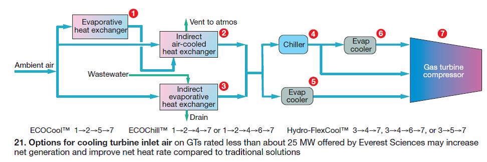
To understand what Everest has done in principle, follow the processes described in Fig 21. The company offers three general solutions: ECOCool™, ECOChill™, and Hydro-FlexCool™. Each begins with ambient air and ends with conditioned air being injected into the GT compressor.
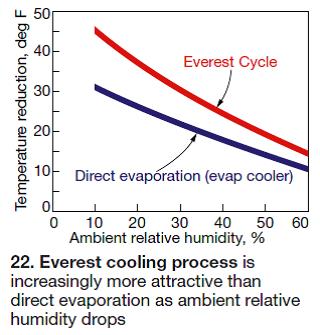
In the ECOCool process, ambient air is cooled by evaporation in a high-tech crossflow heat exchanger (1 in the flow chart) – an entirely different device than the wetted-media evap coolers you are most familiar with (Fig 22). Air from (1) is used to cool ambient air for combustion in an air-cooled heat exchanger (2).
Key point: Combustion air flowing through (2) is cooled, and its density is increased, without adding moisture. Thus, for a given temperature reduction, mass flow is higher. More specifically, ECOCool reduces the enthalpy of the combustion air (removes heat energy), unlike conventional evaporative methods which cool air, but cannot change its enthalpy. This sensible cooling process resembles a chilling cycle but it uses fans and pumps rather than large compressors.
Cool air leaving (2) next passes through a wetted-media evap cooler (5) before entering the compressor (7). Important to keep in mind when you dig into the company’s literature at www.everestsciences.com is that the two-stage hybrid cooling process incorporating steps (1) and (2) is referred to as the Everest Cycle™. ECOCool is the name for the Everest Cycle coupled with the air-wash cooling step in (5).
Everest’s Marcus Bastianen, PE/SE, sums up the benefits of ECOCool this way: “The hybrid process supplies air to the compressor at less than the ambient wet bulb using about the same amount of power required for conventional evaporative methods. It provides turbine inlet air at higher density than any competing evaporative technique.”
ECOChill flow path is (1), (2), and (4), where the last is the chiller package. A final evap cooling step (5) may be added to optimize the offering for certain ambient conditions. ECOChill reaches target turbine inlet air temperatures with a chiller that is substantially smaller than one for a conventional refrigeration package because former is less directly affected by ambient conditions. Air entering the chiller (4) is at a temperature significantly lower than ambient, some cooling already having been done by the Everest Cycle.
The benefits, says Bastianen, are “lower chiller capital and operating costs, more net turbine power output, and higher net engine efficiency. ECOChill also offers users the flexibility to optimize their cooling processes as ambient and operating requirements change.”
Once again, understanding the Everest lingo is important before dialing up the company’s website: h3 is the name Everest uses for its supplemental mechanical chilling process. ECOChill incorporates both the Everest Cycle and h3.
Note that a separate cooling tower is not required to support chiller operation. Air discharged to atmosphere from the indirect heat exchanger (2) is sufficiently cool to condense the refrigerant. An induced-draft fan is integrated into the Everest package to drive the condensing process.
Hydro-FlexCool is a variant of the Everest Cycle. Its indirect evaporative heat exchanger (3) uses brackish or reclaimed water and air as the first step in TIC. A similar heat-transfer device has been used on large chiller-equipped frame GTs for condensing refrigerant rather than for cooling combustion air.
The Hydro-FlexCool option is ideally suited for gas turbines in arid, remote areas. Units in pipeline service come to mind because locally available brackish well water can be used as the cooling medium.
Advantages of water-to-air heat transfer over air-to-air include the following: simpler TIC system; less heat-transfer surface for a given duty; and evaporation of some plant wastewater (if this is the water source), thereby reducing the amount of wastewater that may have to be treated prior to discharge or stored in onsite evaporation ponds.
The density of combustion air leaving (3) can be increased by using a chiller (4), with or without the final evaporative cooling step, or by simply following the evap cooler route through heat exchanger (5).
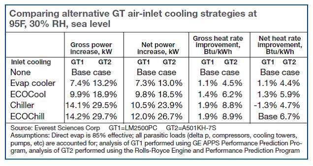
Performance improvement offered by ECOChill (Everest Cycle + h3) for LM2500 and A501KH-7S GTs is compared in the table to a conventional chiller, ECOCool, evap cooler, and base case with no TIC. Data show the significant improvement in net power and net heat rate offered by the Everest Sciences solution over a standard chiller for both engine types.
Reason is that the reduction in ambient air temperature achieved by the Everest Cycle becomes the starting point for the h3 cycle. This means substantially less refrigeration is required to reach a target turbine air inlet temperature than for the chiller-only case. The Everest solution’s much lower parasitic load means added revenue at lower cost for the plant owner.
If you want to see the results graphically, visit the Everest website and review the psychrometric charts. If your thermodynamics has gotten rusty over the years, you might want to review how to use psych charts before logging on. The bottom line, as the two case histories that follow attest, is that the Everest solutions deliver on their promise. All you really have to figure out is if the economics work for your plant.
The electrical generator is capable of 6 MW, but even with a Cheng Cycle upgrade, which uses steam injection for NOx control and power boost, the GT wasn’t capable of doing more than about 5.7 MW on a typical day. On hot days, when summertime temperatures often hit 110F-115F, the engine couldn’t do better than about 5.2-5.3 MW.Case history 1. The utilities manager for a food processing plant located in the California desert told the editors the facility’s A501K was installed in 1986 and provided all the power required onsite. Engine operation is controlled to match plant demand. The unit operates in parallel with the grid, so if it is forced out of service, continuity of electrical supply is preserved. The cogeneration facility also has a single-pressure heat-recovery steam generator (HRSG).
The utilities manager the editors spoke with hired on nearly seven years ago. It didn’t take him long to tire of the poor performance from the single-stage conventional evap cooler. By then, the cooler had been operating for almost 20 years and had seen better days; the plant runs about 8500 hours annually. Further deterioration in swamp-cooler performance and the GT might not be able to meet in-house demand on some days.
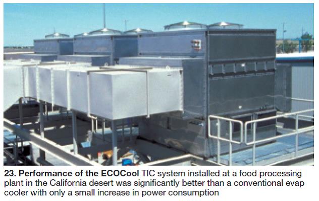
He investigated the conventional alternatives – new evap cooler, fogging, chiller – and what would later become Everest’s ECOCool offering. Performance of the Everest TIC system installed was significantly better than the single-stage cooler with only a marginal increase in power consumption (Fig 23).
With the Everest upgrade, the engine can produce 5.6 MW on very hot days, an increase of 300 to 400 KW over that possible with the old evap cooler. Thus less steam is needed for power-boost service, saving on the cost of high-quality makeup water. Addition of the h3 package wasn’t considered because this plant already is producing all the power it needs with just the Everest Cycle front end.
Well water high in calcium and magnesium is used in the evaporative heat exchanger module (component 1 in Fig 21). The design is tolerant of bad water, the utilities manager said. Cycles of concentration are controlled by automatic blowdown based on water conductivity. Only real maintenance is to clean and flush the sump at the bottom of the TIC package quarterly.
The utilities manager told the editors that the Everest equipment has met expectations and that the company always has shared improvements it has made to the equipment installed.
Case history 2. Chief Engineer Tom Peltsch, Sonoco Canada, Brantford, Ont, also shared his experience with the Everest Sciences equipment: Different climate and different operating paradigm, but the same positive results. Peltsch’s powerplant provides all utilities to an ageless mill which now blends a variety of recycled cardboards to make the spiral wound paper used in the manufacture of containers for potato chips and other products.
A new generating plant installed in 1993 is powered by a gas-only Allison KB501 GT capable of producing 4 MW; mill requires 3 MW. Facility has a single-pressure, supplementary-fired HRSG and a gas/oil-fired 40,000-lb/hr packaged boiler to assure continuity of steam supply. Peltsch stressed the need for high reliability to satisfy mill commitments and to export power to the grid when financially viable.
The gas turbine was installed with only media filters on the front end. No cooling of inlet air would be required in Canada, or so engitemperatures and humidity in the 90s the plant retrofitted an Everest Cycle + h3 solution. Peltsch, who was not at the plant when the purchase decision was made, said there was little institutional knowledge on the matter.
The way the plant operates today testifies to the operational flexibility of the TIC system. The chief engineer said the Everest Cycle is turned on about May 1 and off by the end of October. Plant personnel continuously monitor ambient and turbine inlet conditions and bid into the hour-ahead market when there’s money to be made.
Grid and gas prices are displayed in the control room, and with the aid of a weather station installed on the plant site and software to run revenue calculations, plant personnel can exploit an opportunity simply by turning on the h3 (chiller) portion of the Everest TIC system.
Peltsch said the plant can dispatch to the grid 24/7, but the actual time it does depends on price. Operators minimize export and burn less gas when the grid price is low. He thought the chiller ran about 30% of the time during the May to October period.
Operators are continually fine-tuning operations to squeeze top performance from the plant, Peltsch continued. There are times a fan may be turned off because it’s not needed and a few more pennies drop into the revenue basket. The GT compressor is online washed weekly to assure maximum efficiency.
Water used in the Everest Cycle comes from the city main. It is monitored for conductivity and bacteria to guide the continuous blowdown system. Peltsch said that the system requires very little maintenance but because a lot of dust is generated in the handling of bales of cardboard, the sump must be washed out on a weekly basis.
Texas chill
Brazos Electric Power Cooperative Inc is not a household name outside of Texas, but the company’s Jack County Generation Facility is well known to industry insiders for its operations and maintenance know-how. In fact, Operations Superintendent Troy Cannon and Water Plant Supervisor Ronnie Johnson recently accepted one Best of the Best and two Best Practices Awards for the plant’s innovative work in improving the performance of zero-liquid-discharge systems (see awards article elsewhere in this issue).
Readers may recall that the first 7FA-powered 2 × 1 combined cycle the cooperative installed at its Bridgeport site in 2005 was built in 17 months and for much less than the market price by judicious purchase of secondary-market equipment, which included evap coolers in the air inlet house.
Jack County rarely is offline. Brazos supplies power to its 16 member co-ops (primarily residential load) and one municipal system, and sells into the spot market when profitable and excess capacity is available (sidebar). Thus the ability to maximize generation is important—as are plant reliability and efficiency. Also important to Brazos: Minimize the risk of having to buy power at the market price to meet its commitments.
When Brazos began design of a second 2 × 1 for the Jack County site (now about 70% complete), it investigated an inlet-air chilling option to maximize output. The combined cycle was capable of producing 560 MW on a hot summer day (95F dry bulb, 75F wet bulb, 41% RH) with evap coolers; 605 MW was possible with a chiller capable of delivering 50F air to the compressor.
Further studies revealed that retrofitting a chiller on Unit 1 made economic sense and Brazos moved forward immediately. Turbine Air Systems (TAS), Houston, was selected to design and install the system (Fig 24). The project began Dec 1, 2008 and was complete by July 4 (Figs 25, 26).
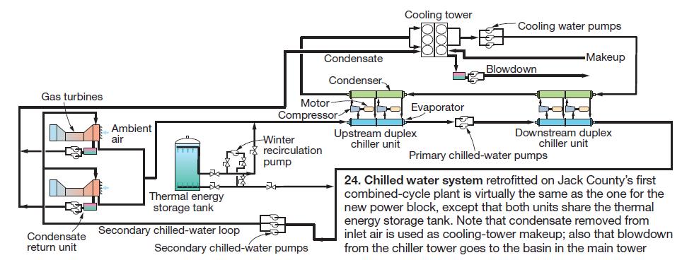
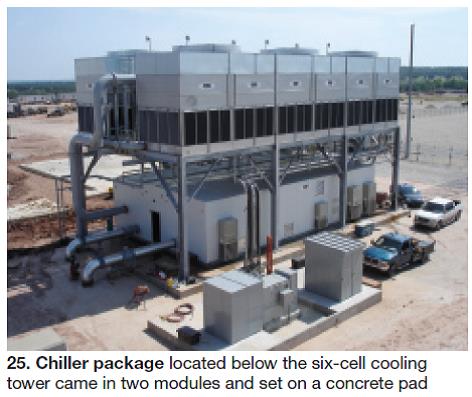
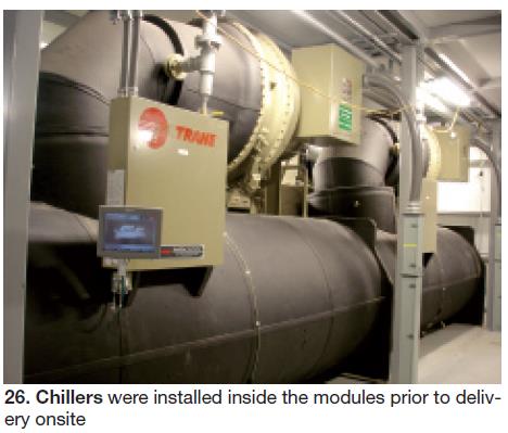
The system described in Fig 24 provides a total of 9100 gpm—a nominal 5900 gpm from the chiller, 3200 from storage—to the air-inlet coils on both gas turbines. Cannon, who was on the phone with the editors along with colleagues Carl Raines, operations supervisor, and Greg Peterson, shift supervisor, said the chilled water system was purposely undersized to minimize auxiliary power demand. The auxiliary power requirement is 5 MW.A 6.1-million-gal thermal energy storage (TES) tank was installed later that summer and integrated into the chilled water system. The chiller package (two nominal 7300-ton duplex modules) is designed to operate independently or in tandem with the storage tank. The TES tank is designed to receive cold water from the chiller package during off-peak hours (charge cycle) and to supplement chiller output during peak hours (discharge cycle).
On most summer days, the chiller runs around the clock although turbine inlet cooling is required for only 14 or 15 on-peak hours; remainder of the time is spent charging the TES tank, which can store up to 111,000 ton-hr of chilling capability. The chilled water systems for combined-cycle Block 1 and Block 2 are identical and share the TES tank.
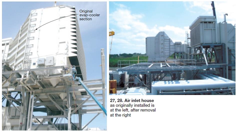
Cannon said changing from an evap cooler to chiller was relativelyplished in three weeks during a scheduled outage in April 2009. The original air inlet house (Fig 27), supplied by Donaldson Company Inc, Minneapolis, was removed on the far side of the transition duct just ahead of the inlet-bleed-heat section and where the duct leading to the compressor inlet on a standard 7FA installation turns downward (Fig 28).
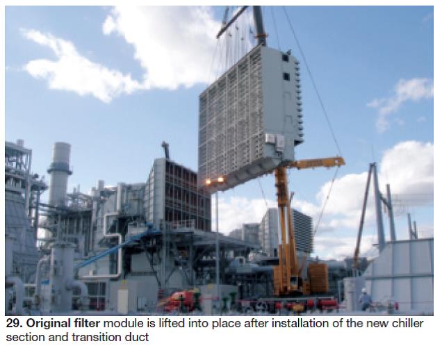
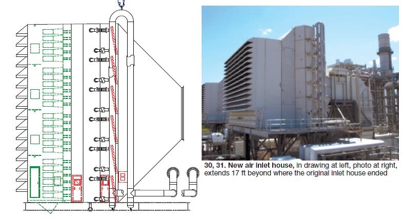
The piping manifolds at the air-inlet chilling coils are reverse-return for self-balancing, uniform flow distribution to all 14 coils serving each gas turbine under all operating conditions. Temperature control is via a modulating pneumatic butterfly valve in the return line from each coil.After the new chiller section and transition duct were installed, the original filter house—minus the evap cooler—was reinstalled (Fig 29). The mod extended the air inlet house by 17 ft over the generator. TAS subbed out modification of the inlet house to Braden Manufacturing LLC, Tulsa (Figs 30, 31). This work included construction of the chiller section using coils supplied by Aerofin Corp, Lynchburg, Va. Williams Industrial Service Group, Atlanta, a sister company of Braden’s, performed the field work.
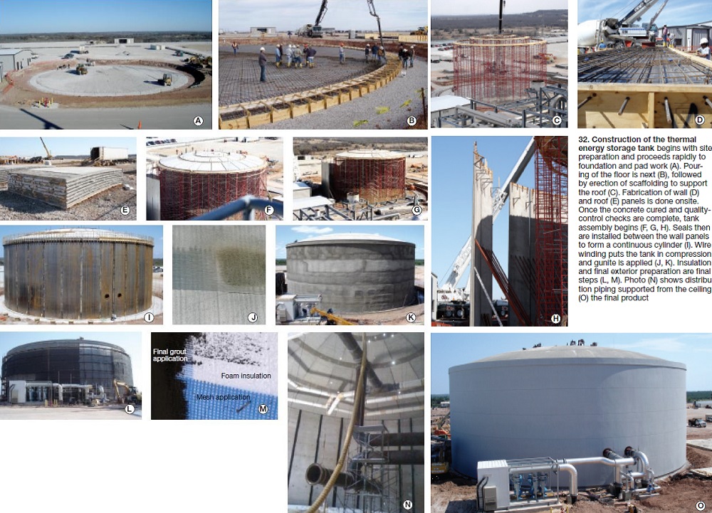
TAS subcontracted the thermal energy storage tank to Natgun Corp, Wakefield, Mass. The company specializes in wire-wound concrete tanks (Fig 32).
Project began by clearing an access roadway around the tank perimeter and leveling the ground for the casting beds used to make wall and dome panels. Casting beds are placed around the tank to facilitate the lifting and placement of panels. Precasting panels onsite combines manufacturing plant quality with convenience. Each panel must pass compressive-strength tests before it is qualified for use.
Natgun’s monolithically cast membrane floor is designed to flex in response to minor settlements. The entire tank floor is cast, vibrated, screeded, and final-finished in one continuous operation.
The company says an important feature of its tanks is the use of a watertight steel liner, or diaphragm, embedded in the tank wall. The vertically ribbed diaphragm is equipped to provide a mechanical lock within the concrete.
The construction process seals all spaces between adjacent panels, making the tank a continuous cylinder with an exterior steel shell and corrosion-resistant concrete interior wall. A water-stop encased in shotcrete creates a watertight connection between the wall and floor.
Natgun tanks are placed in permanent compression using a wire pretressing method in compliance with standards of the American Water Works Assn. Here’s how this is done: A half inch coating of shotcrete is applied to the steel diaphragm and multiple layers of continuous wire are individually encased and bonded in the concrete.
After the wire winding is complete, vertical screed wires are placed on 2-ft centers around the tank circumference to assure that the final coat is applied in uniform thickness. The shotcrete is screeded and given a final finish. A 3-in. layer of Styrofoam™ insulation is applied between the winding wire and the final exterior shotcrete application. The wall and dome receive a two-coat architectural treatment to provide a uniform color and to seal the tank surface.
Winterization. Cannon and his operations colleagues said the biggest challenge posed by the chiller is winterization. Weather patterns in this area are such that you can have a serious cold snap (lower than 30F) and then rebound in a matter of hours to temperatures in the 70s or higher. Brazos can use the chillers during warm days to optimize its operation.
Plant personnel need a method to protect the coils in cold weather while allowing their operation within a few hours. Cannon thinks they’ll use the chiller 40 to 50 days between November 1 and April 1, and that temperatures will be 80F or higher a third of that time.
Cannon, Raines, and Peterson figure glycol is probably part of the solution, but no definitive solution has been implemented. Currently, plant personnel winterize the chilled water system by draining the air-inlet chilling systems and cooling-tower basins of water and flushing a glycol/water mixture through the coils before sealing up the system until spring.
Long term, one option is to drain water from the chiller coils and chilled water circuit and fill that portion of the system with a mixture 25% glycol/75% water to provide freeze protection down to 15F; also, to add cooling-tower basin heaters. The glycol and basin heaters would permit wintertime operation of the chiller packages and the coils with the TES tank isolated from the system.
When the chilled water system is brought out of winter layup, the TES tank would be reconnected. Its water would push the glycol/water mixture out of the coils and chilled water piping and the fluids would mix in the TES tank.
A downside of this approach is that annual glycol costs could run as much as $100,000. Remember, too, that glycol in high concentrations inhibits heat transfer. However, it could take 30 years or so to build up the concentration of glycol in the TES tank to 30%, where it would be prudent to drain and flush the entire system.
Other options include these: (1) Heat water in the chilled water circuit using steam from an auxiliary boiler, and (2) Replace the water with glycol for the winter months and, in spring, drain the glycol to a storage tank for reuse.
The last option seems most effective, but it would require a one-time investment of approximately $200,000 to implement. Meanwhile, protecting the cooling tower and other small piping systems also presents winterization challenges that could prevent a quick return to service.
Brazos is Texas’ largest G&T co-op
Brazos Electric Power Cooperative Inc, Waco, organized in 1941, was the first generation and transmission (G&T) co-op formed in Texas. It continues to be the largest G&T in the state with a service territory extending across 68 counties from the Texas Panhandle to Houston and a peak demand of about 2900 MW.
Brazos is the wholesale power supplier for 16 member/owner distribution co-ops and one municipal system. Each cooperative member is represented on the company’s board of directors. Brazos’ mission is simple: Generate, procure, and transmit power at the lowest possible cost.
The company owns four generating facilities: Jack County, described in the main text; Johnson County, a 270-MW 1 × 1 combined cycle also being upgraded with a mechanical chiller system; North Texas Plant, a 71-MW steam/electric station; and the R W Miller Generating Station, which can produce about 600 MW from its conventional steam and gas-turbine-based generating resources.
Fine-tuning chiller operation to assure top performance
Palomar Energy Center, a 7FA-powered 2 × 1 combined cycle, owned and operated by San Diego Gas & Electric, a Sempra Energy utility, began commercial operation April 1, 2006 with evap coolers in the plant’s air inlet houses. But they were not ideally suited for the Escondido (Calif) location or conducive to a strong balance sheet. For a backgrounder on Palomar, access www.combinedcyclejournal.com/archives.html, click 4Q/2006, click the plant name on the issue cover.
Simply put, with evap coolers, the full capacity of the plant was limited by ambient conditions. Palomar was capable of 565 MW, but on a hot, humid day could only produce 505 MW. GT capability changed day to day, hour to hour. The inability to accurately forecast capacity limited the plant’s revenue, according to Dan Baerman, director of electric generation.
Plant Engineer Brian J Martin, PE, hired on at Palomar shortly after COD and he recalled that internal discussions on the value of a chiller retrofit already were under way. Martin added value to the dialog because he was party to a successful evap cooler-to-chiller conversion a couple of years earlier at a major California cogeneration plant.
The decision to retrofit chillers at Palomar was a big one for SDG&E because the plant was new and the company had just re-entered the generation business. Recall that California’s major investor-owned utilities had been ordered by the state to divest of their generation assets several years earlier.
But economic analyses conducted collaboratively among engineering, marketing, and other stakeholders in the company made a compelling case for the conversion and the decision to move forward was made at the end of 2006. The utility wanted a system that would deliver 50F air to the GT.
GE Energy was selected as the turnkey supplier in competitive bidding. The utility already had a relationship with the OEM via a long-term service agreement and viewed the vendor as a company that understood what its customer needed. Another plus: The utility team favored GE’s control system for its functionality.
The plant DCS has overall control of the chiller facility. For example, it decides on the number of chillers to operate and when to turn them on and off. The PLC controls provided for the chiller plant optimize operation of the centrifugal refrigeration machines. Automated operation, combined with highly flexible system design, assures the most efficient operating mode without excessive operator intervention.
Signing a contract early in 2007 and looking ahead to project completion was quick and easy. Interfacing with multiple state regulatory agencies and addressing the concerns of neighbors was time-consuming and challenging at times.
Annual emissions essentially “zeroed out,” Martin said, but SDG&E still had to walk regulatory personnel through the project and the reasons for doing it. Conversion to chilling was considered a new source review because the plant would be producing power that it couldn’t produce previously under certain ambient conditions. The air-quality review took a few months, but it went fairly smoothly, he added.
Review by the California Energy Commission was more involved, Martin continued. The CEC verified all the air emissions data with the San Diego County Air Quality Control District and also evaluated noise, visual impacts, water usage, etc. Then there was a public notice period.
To prevent noise from becoming an issue, the chillers were installed in a sound-attenuated building. Designers also took special care to insure that the chiller building, thermal energy storage (TES) tank, and piping would not be viewed a “visual impairment.”
Water concerns were significant, and neighbors worried about the potential for a cooling tower plume. Interveners surfaced and fussed over this. Note that the existing cooling tower, which was slightly over-designed, could accommodate the refrigeration condensers as well as the main steam condenser.
SDG&E talked over neighbor concerns with the tower manufacturer, SPX Cooling Technologies Inc, Overland Park, Kans, and the vendor produced what Martin called, “an elegant solution.” Inlet heating of GT inlet air under certain ambient conditions reduces the tower’s cooling load with no increase in water consumption. In fact, judicious use of inlet heating may reduce annual water consumption somewhat.
In addition, charging of the TES tank typically would be done at night when the heat load on the tower typically is close to or at the daily minimum (cooler ambient, off peak electric production) and there would be no visible plume. Another benefit of having a TES tank is that nighttime charging enables GT operation at a higher efficiency point than would be possible without it.
The CEC approved the project early in 2008, about a year after SGD&E and GE had signed the contract. Commissioning of the chilled water system was done in fall 2008 and the project was declared commercial by yearend. Martin said the primary operational impact—installation of the coils in the air inlet house—was completed during the spring outage. Two other operational impacts—the chiller condenser circulating-water connection to the cooling tower, and medium-voltage electrical work (compressors and circ-water pumps are powered from the 4.16-kV bus)—were completed during later minor outages.
The central chiller plant, which has one supply and one return header, was designed “full-size” so to speak. It met system requirements without taking any credit for having a TES tank rated at 39,000 ton-hours. Four compressors, arranged in two redundant pairs, are capable of delivering the 9000 tons of refrigeration needed to assure 50F air to the GTs on a 97F day with 30% relative humidity.
Think of the chillers as an alternative to adding an LM6000 in terms of capacity, at a much lower heat rate—7000 Btu/kWh versus 10,000 for the peaker—and with no increase in emissions. Plus, they can reach maximum capability in about 10 minutes—table stakes in the grid world for fast-start capacity.
System arrangement. The chilled water system as it appears on the operator’s screen with critical pressures, temperatures, flow rates, and equipment on/off indication is at the left in Fig 33, a simplified flow diagram to the right.
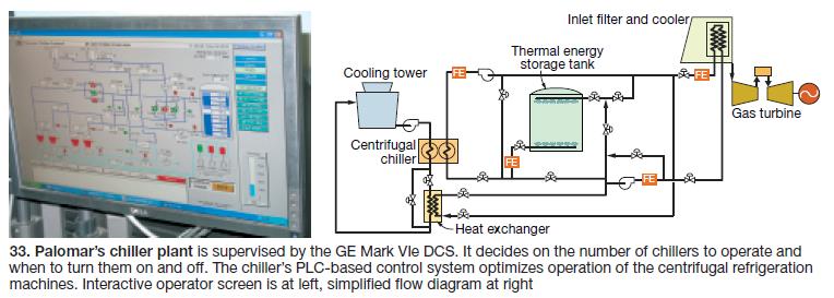
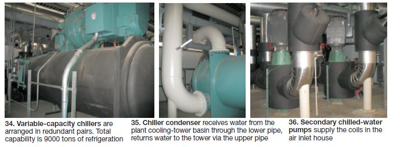
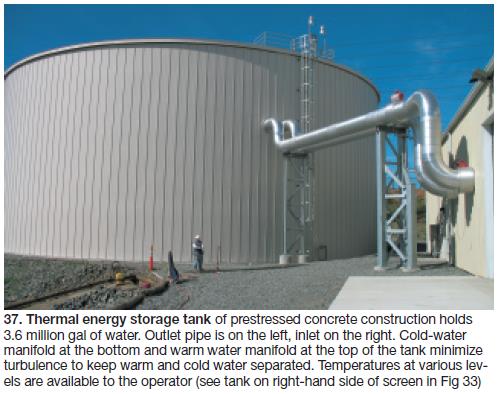
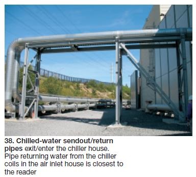
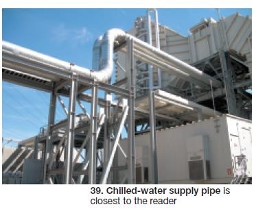
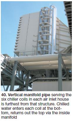
Three 50% auxiliary circulating pumps, installed in a small basin connected to the cooling-tower basin, deliver water to the chiller condensers. The small basin, protected from direct sunlight to prevent algae growth, was installed as part of the chiller-building construction project.Three 50% primary pumps deliver chilled-water returning from the air inlet houses, or warm water from the top of the TES tank, to the centrifugal chillers. Cold water leaving the chillers is routed to the bottom of the TES tank or via the secondary pumps (also 3 x 50%) to the coils in the air inlet houses. The secondary chilled-water pumps also can take water from the top or bottom of the TES tank to supply the coils (Figs 34-40).
A plate-and-frame heat exchanger is installed in the circulating-water return line to the cooling tower. It recovers heat for warming compressor inlet air as a means for improving GT performance at low loads and in cool weather. Capturing heat from the circ-water return water reduces the thermal load on the cooling tower and conserves water.
Operating flexibility
Baerman and his team drew on past experience of personnel and conducted an economic analysis with all viable options. Ultimately, station staff decided on eight modes of operation depending on ambient and other conditions. The details:
Mode 1. Turbine inlet cooling (TIC) using only the chiller. Electric chillers cool the water that absorbs heat from incoming combustion air. This mode of operation is used only when the thermal energy storage (TES) tank is out of service.
2. TIC using only water discharged from the TES tank. The centrifugal chillers are not operated, to conserve parasitic load. Chilled water stored in the TES tank is pumped directly to the GTs for inlet cooling. This is the most common daytime operating mode and the one that offers the best heat rate.
3. TIC with simultaneous chiller operation and TES tank discharge. This mode achieves maximum turbine inlet cooling capability and meets plant requirements on an extremely hot and humid day. It typically is used on the morning of an expected warm day to “save the tank.”
4. TES tank charging. The centrifugal chillers charge the TES tank; gas-turbine inlets are neither cooled nor heated in this mode. Note that the tank can be charged without operating the GTs. This is, perhaps, the second most widely used option; it assures a “full” tank in terms of cooling capability.
5. Inlet heating/freeze protection. A heat exchanger is used to transfer heat from the circulating water system to the chilled-water loop. The warm water flows to the GT for inlet heating. This mode is used when (a) ambient temperatures approach freezing, regardless of GT operating status or load, and when (b) GTs are operating at part load with ambient temperature less than the circ water/cooling tower temperature. Inlet heating at part load (with IGVs at less than fully open) increases GT efficiency.
6. Inlet heating while TES charging. While charging the TES tank with the chillers, the chiller waste heat is transferred to the chilled water loop via a plate-and-frame heat exchanger. This takes the chiller load off the cooling tower (conserving water and fan power) while simultaneously providing extra warm inlet heating to the part-loaded GTs to improve turbine efficiency. This mode is not used as frequently as Mode 5.
7. Free heating and free TES charging. This mode takes advantage of warm days and cool nights. At night, warm TES tank water is circulated through the gas turbine to provide inlet heating while cooling the TES water. During the day, the cooled water is circulated to the gas turbine for inlet cooling, which heats the TES water. Ambient conditions conducive to this option do not occur frequently. However, on a really cool evening (35F-40F) you can extract the warmer water from the top of the tank and return it at a temperature consistent with that at the bottom of the tank.
8. Efficient TES charging. This mode is preferred when the ambient temperature is lower than the TES water temperature, but not cool enough for free TES charging. The warm water from the top of the TES tank is pumped through the turbine inlet coils for initial cooling. It is then pumped through the second chiller stage for final cooling before being returned to the bottom of the TES tank. The centrifugal chillers can be run at greatly reduced capacity in this mode. ccj