


Effingham County Power
Owned by The Carlyle Group
Operated by Cogentrix
525-MW, gas-fired, 2 x 1 combined cycle located in Rincon, Ga
Plant manager: Nick Bohl
Auxiliary-boiler blowdown relocation
 Challenge. The auxiliary boiler’s superheater had been a continuous problem. It is an electric superheater containing several 480-V heating elements. Over time, a significant reduction in current to the unit was occurring, and damage to the heater element terminals also was apparent.
Initially it was thought that this damage was caused by steam leaks through the gasket of the heater-element head. However, while inspecting the superheater, personnel found most of the damage was occurring at the lower right-hand section.
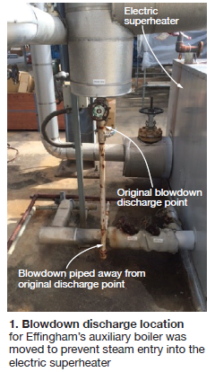
Monitoring of the next startup revealed that when the aux boiler was being blown down, the steam was being discharged directly into the electric superheater.
Solution. The steam was going directly into the air vents of the casing, filling the entire electrical enclosure. These vents could not be obstructed to prevent steam entry because this would not allow the hot air in the superheater to escape.
To protect the electric superheater from the steam, O&M personnel decided to redirect the blowdown line. The discharge of the blowdown line is now well clear of the electric superheater and steam entry into the enclosure is no longer an issue (Fig 1).
Results. Since redirecting the blowdown path of the auxiliary boiler, the condition of the electric superheater has greatly improved. The total amount of amperage has increased, meaning it is operating more efficiently and at higher capacity. In the past, the amperage would trail off over time, markedly. Now the current is stable for a much longer amount of time eliminating the need to shut down for repairs.
Project participant: Chris Hofer
Freeze protection system enhancements
Challenge. The January 2014 record-breaking cold spell shut down the plant because the freeze protection system was not working properly. Process lines and transmitters were freezing. Several transmitters had to be replaced. Insulation, lights, and temporary heat trace were installed to make it through the cold spell.
Some of the damaged instrumentation was not found until months later because of erratic operation. The drawings that were furnished for heat tracing were not thorough or accurate. Example: The heat-trace junction boxes were not marked with circuit numbers making it difficult to trace down the correct circuits.
Every issue had to be investigated and walked down to verify circuitry, making it very difficult and time-consuming to troubleshoot. The plant has seven electrical heat-trace panels with over 60 different circuits. Some circuits have as many as 13 runs that branch out to heat trace, heaters, and/or indicating lights.
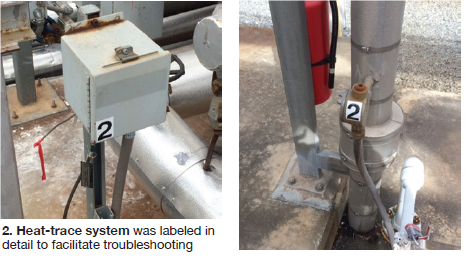
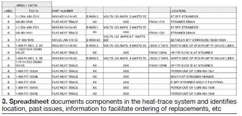
Solution. The complete heat-trace system was walked down, verified, repaired, and labeled (Fig 2). A spreadsheet was created to document the mapping of the heat-trace system and any issues that arise (Fig 3). It contains all pertinent information needed if a repair or replacement is necessary. All circuits have been clearly marked and recorded on the spreadsheet, which is kept on the shared drive for all staff to access.
Results. With the heat-trace system labeled and documented, the plant is now able to troubleshoot and repair the circuits without wasting man-hours. Plant instrumentation has better freeze protection, resulting in fewer costs for replacing it. Most importantly, the reliability of the plant is no longer affected by freeze issues.
Project participant: Cheryl Hamilton
Increasing lube-oil-pump bearing life
Challenge. The original design of the Buffalo Model VCRE pumps that provide lube oil and seal oil to the gas turbine were equipped with a grease-lubricated upper thrust bearing, fitted with a pressure-cup type automatic greaser. To grease the bearings, you tightened the pressure cap on the greaser and the bearing is lubricated.
This original application would have worked, but because the bearing cover was not fitted with grease relief, over a period of time the grease compacted within the bearing cover and eventually blew out the bottom seal. Once the bottom seal was compromised, the grease would leak out of the bearing cover, and bearing, and cause the upper thrust bearing to fail.
A failure occurred about every 7500 to 8000 run-hours. The installation arrangement with tandem pumps piped to a common header made it impossible to remove one pump at a time. In addition, to repair the failed pump bearing, the entire unit had to be shut down and allowed to cool down.
Next, the lube-oil header piping above the pumps would be removed and lastly, the failed pump removed for repairs. Repair costs associated with the foregoing is minimal compared to the costs of missing a full day of power production.
Solution. To extend the run time of the upper thrust bearings and improve unit dependability and reliability, the O&M team decided to retrofit the upper thrust bearings with a forced feed of lube oil.
The forced oil feed to the bearing was obtained from two sources, the first being the lube-oil header just downstream of the pressure regulator. This would provide lube oil, when the unit was running or on turning gear. If the unit was down or off turning gear, the lube-oil feed was provided from the discharge flange of the seal-oil system. These two sources ensured that the lube-oil pumps would have a continuous supply of oil to the upper thrust bearing.
Next, a stainless-steel fitting was installed into the lube-oil header in the same proximity as the lube-oil header temperature switches, along with a lockable-handle ball valve to provide the first source of forced oil feed to the upper thrust bearing.
The second source of forced oil feed was obtained from an existing ¼ in. pipe fitting on the discharge piping of the seal-oil pump. Oil then is pumped through in-line filters, regulating valves, check valves, and individual isolation valves. Finally, the oil is pumped through a 0.040 in. orifice to provide the correct amount of forced oil feed to the two auxiliary lube-oil pumps and the seal-oil pump.
Because of the lower run times of the DC lube-oil pump, the forced oil feed mod was not implemented on this pump at the time of installation. However, provisions were made in the original installation of the forced oil feed tubing to allow for this at a later date, if required.
Results. Prior to installation of the forced oil feed system, the plant was experiencing a pump bearing failure every two years, or less. Since installation in 2005, the plant has not experienced a failed bearing. The replacement of one or two top-bearing cover seals was needed but this can be done without removing the pump and related piping. This means personnel can make these repairs with the units running.
The associated cost of the seals and bearings is minimal compared to the cost of lost production, not to mention the vast improvement in reliability of the facility without a single bearing failure.
Project participant: Alan Sparks
Sensing lines for fuel-gas-train control valves
Challenge. Effingham experienced below-normal temperatures in recent winters causing multiple freezing issues throughout the plant. Among the components affected were the fuel-gas-train monitor and worker control valves. The upstream and downstream sensing lines to these valves accumulated moisture from continuous operation at ambient temperatures below normal.
When moisture blocked the upstream sensing line, the control valve would sense lower inlet pressure and would open more to maintain downstream pressure. This would raise downstream pressure above the design value, causing safety valves on the fuel-gas filter/separators to lift.
Once the water cleared the line, then the valve would sense a higher inlet pressure, causing the valve to close. As long as moisture was present in the sensing lines, the valve would continue to cycle.
If moisture was present in the downstream sensing line, the control valve would see a lower system pressure, causing it to open to increase downstream pressure. Once the moisture cleared the line, the valve would respond by closing, resulting in rapid cycling of the control valves.
This cycling of the control valves resulted in low inlet pressure at the gas turbines. A load runback was initiated to protect the turbine from low pressure in the fuel-gas system.
The relief valves that lifted to protect the fuel-gas system are only designed for one cycle. Typically, the relief valve would not seat properly and result in fuel gas leaking into the environment. Since the plant doesn’t maintain spare relief valves in inventory, Effingham would have to shut down to replace the relief valves.
Both the GT runback and relief-valve maintenance prevented the facility from meeting the day’s scheduled dispatch and the plant would be unavailable until the relief valves could be replaced or rebuilt. This happened on several occasions and each time the plant would have to shut down, if running, and the relief valves rebuilt.
During the winter, the plant lost approximately $42,000 because of sensing-line freeze-up.
Solution. Low-point drains with a double-block configuration were installed in the sensing lines (Fig 4). With them installed, plant personnel can easily drain the accumulated moisture.
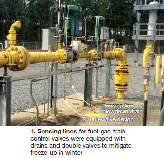
The fuel-gas trains are isolated and moisture is drained prior to the onset of low ambient temperatures. Also, during the winter, plant personnel drain moisture from the sensing lines monthly to prevent freezing issues.
It took approximately two days to install the additional drain legs to the sensing lines in early 2010, during plant downtime. There was no cost associated with the installation other than the tubing, valves and labor. The tab was approximately $1,000.
Results. After installing the low-point drains for the fuel-gas-train control valves in 2010, the plant’s freeze protection procedure has plant personnel drain moisture from the sensing line monthly during the winter. The facility has had no further issues with freeze-up of these sensing lines and there has been no loss generation or revenue since installation.
Project participants: Howard Beebe and Michael Gilbert