


By Mitch Cohen, Turbine Technology Services
(www.turbinetech.com)
Fuel options available to most owner/operators of gas-turbine-based powerplants include natural gas and distillate oil, as well as medium- and low-Btu gases from a variety of sources. Recent fuel-price increases suggest that the ability to switch to more economical fuels in response to price fluctuations is particularly critical in deregulated power markets. In other instances, the ability to burn an alternative fuel may be necessary to prevent shutdowns caused by supply constraints. In both cases, fuel-system modifications often are needed to permit fuel switching.
Besides the cost and availability of fuel, mods to existing fuel systems also are driven by the need to achieve reductions in non-fuel O&M costs and/or to increase gas turbine (GT) reliability. This often is true for dual-fuel systems that operate primarily on natural gas and rarely, if ever, burn distillate.
Retaining distillate capability when not wanted or necessary has a negative impact on both maintenance cost and unit reliability. Reason is that dual-fuel systems are more complicated and prone to mechanical or control- system malfunctions than either gas- or liquid-only fuel systems. In addition, the greater complexity of dual-fuel systems adds to the time and labor cost of assembling and disassembling the combustor during maintenance outages and to the cost of refurbishing/replacing dual-fuel hardware—even when distillate is not burned.
The self-contained sections that follow outline some of the important design considerations and general steps involved in making various fuel-system modifications.
1. Single- to dual-fuel conversion
The most common type of fuel system modification involves converting from single- to dual-fuel capability by enabling use of both distillate oil and natural gas. This mod offers the flexibility to switch to a less-costly fuel in response to price fluctuations or to a backup fuel if the primary fuel supply is interrupted.
Liquid-only to dual-fuel conversion
In considering conversion from a liquid-only to a dual-fuel system, it is assumed that the existing combustor is a standard, diffusion model that uses either water or steam injection for NOx reduction. (No OEM is currently known to offer a liquid-only dry low-NOx (DLN) system.) This same diluent would be used for NOx reduction after conversion to a dual-fuel diffusion combustor. Conversion to a dual-fuel DLN combustor has the added requirement of an entirely new combustion system.
A liquid-only to dual-fuel conversion typically involves the addition of the following systems and components:
1. Gas pressure regulator.
2. Gas fuel treatment system— including filters and liquid separators. For DLN systems, fuel heating also may be necessary.
3. Flow-control hardware, including stop/speed ratio valve, gas control valve(s), and associated servo valves and other controls instrumentation. Note that for diffusion combustors a single gas control valve is needed. DLN systems require multiple gas control valves which generally will be located on an off-base fuel skid with the stop valve.
4. Gas piping and turbine-compartment fuel manifolds.
5. Nozzle/combustor mods: For conversions that maintain the diffusion combustor, dual-fuel nozzles replace the gas-only nozzles; for conversion to a DLN combustor, the entire diffusion combustion system must be replaced.
6. Air purge systems (valves, piping, and instrumentation) for gas, liquid fuel, and water injection (if present) supply circuits. The purge system prevents the backflow of hot combustion products into the fuel-nozzle circuits not in use.
7. Control system software and I/O mods.
Gas-only to dual-fuel conversion
Conversion from either a gas-only diffusion or DLN combustion system to dual-fuel operation requires the addition of the following systems and components (exceptions are noted):
- Liquid-fuel forwarding system from the main supply tank.
- Distillate filtration system.
- Flow control hardware— including high-pressure fuel pump, flow divider, stop valve, bypass valve, and associated servo valves and other control instrumentation.
- Atomizing air (A/A) system (depends on turbine model). Options are an accessory-gear-driven main A/A compressor and a motor-driven booster air compressor for startup, or one or two (main and backup) motor-driven A/A compressors mounted external to the engine base.
- Dual-fuel nozzles to replace the gas-only nozzles.
- Air purge systems (valves, piping, and instrumentation) for gas, liquid fuel, and water injection (if installed) supply circuits.
- Diluent injection system for NOx reduction. If the gas-only combustor is a DLN system, then a water injection system must be added for NOx reduction when operating on liquid fuel. If the gas-only combustor is of the diffusion type, it probably has an existing water or steam injection that can be used when burning distillate.
- Control system software and I/O mods.
Comparing gas-only and dual-fuel systems
Figs 1 and 2—typical piping schematics for DLN gas-only and dual-fuel systems, respectively, for a large frame machine—illustrate the dramatic increase in the number of mechanical components, and complexity, of the dual-fuel system relative to gas only. And these diagrams do not show the many I&C components required—including pressure, temperature, and valve-position switches, pressure transducers, solenoids, servos, etc.

One reason for the increased complexity of dual-fuel arrangements is the need to use purge-air systems to prevent backflow of combustion products into the fluid systems not in use (gas, liquid fuel, and/or water). Contributing factors include the need for diluent injection for NOx reduction on liquid fuel. And for DLN systems, there is the complexity of having gas and liquid fuel systems with multiple fuel streams (that is, primary fuel, secondary fuel, etc). Each of these streams, in turn, has its own control valve, manifold, purge system, and control instrumentation.

2. DLN dual-fuel to gas-only conversion
The system complexity required for dual-fuel capability negatively impacts both the reliability and O&M cost of DLN systems. These disadvantages must be accepted by operators requiring such flexibility. However, for sites with a dual-fuel DLN configuration that never operates on liquid fuel, conversion to a gas-only system can simplify operation and reduce cost. Here are some of the headaches you can avoid by converting to gas-only operation:
Valve maintenance. Check valves in dual-fuel DLN systems are a major source of O&M problems. Note that the system in Fig 2 has 60 check valves installed on the liquid-fuel, liquid- fuel purge, and water-injection purge lines. Check valves are notoriously unreliable for either failing to open at the correct pressure or for failing to seal when pressurized in the reverse direction—unless extreme care is taken to maintain scrupulously clean piping.
Thermal damage. A common occurrence on dual-fuel DLN engines that rarely operate on liquid fuel, is for the distillate and/or water nozzle passages to overheat or burn up because of inadequate purge flow during gas operation. This means that a liquid fuel nozzle that is hardly, if ever, used must either be repaired or replaced. Insufficient purge air is usually the result of a stuck check valve or a plugged liquid fuel/water nozzle discharge orifice. These events can be caused by particulate matter that is not filtered from the purge air.
Combustion dynamics. For some dual-fuel DLN combustors operating on gas at low NOx levels, the mere presence of liquid-fuel and water purge-air flows can increase combustor dynamics. A continuous purge is necessary to prevent backflow of combustion gases into the liquid-fuel and water nozzles. But because relatively cold purge air is being injected into the combustion zone in a non-optimal way, instabilities that increase dynamics can occur. Dynamic pressure increases of 2 psi or more have been attributed to purge flows. The increased dynamics impact maintenance costs by both shortening the lives of critical components and increasing repair cost.
Failure of control components and auxiliaries. Dual-fuel systems have many more control components (such as temperature and pressure switches) and auxiliaries (such as an atomizing air compressor) than gas-only systems. Thus they are more prone to failures that initiate runback, shutdown, or tripping of the unit.
Increased outage time. Dual-fuel DLN units require an extensive amount of piping, tubing, and fittings to support liquid-fuel operation. Disassembly and reassembly of this combustion system during an outage typically adds up to two days to the typical schedule for a gas-only arrangement. Result is higher labor cost and lower availability.
If you are considering conversion to a gas-only configuration, keep in mind that if operating conditions change you can reinstall the equipment removed and revert back to the dual-fuel configuration. Main steps involved in converting to gas-only operation include these:
- Disconnecting, and blanking off, liquid-fuel, water-injection, atomizing air, and purge lines.
- Modifying the fuel nozzle from dual-fuel to gas-only configuration.
- Modifying the control program to disable systems related to liquid-fuel operation and their associated alarms and trips.
3. Cofiring natural and medium-Btu gases
Today’s high natural-gas prices make alternative gaseous fuels viable options for GTs.
The alternatives include an array of medium-Btu byproduct fuels from chemical plants and refineries. In addition, low-Btu gas from the gasification of coal and petroleum-coke is gaining interest as a replacement for natural gas in existing combined-cycle plants.
Many factors must be evaluated when considering alternative fuels. These include fuel quantity and availability, physical and chemical properties, combustor type (DLN or diffusion), emissions requirements, and capital available for the conversion. Keep in mind that almost every application for alternative fuels is unique and requires a detailed engineering assessment.
Depending on the quantity and reliability of the alternative fuel supply, it can either be blended with natural gas to achieve an incremental fuel-cost reduction, or used to replace natural gas completely as the primary fuel.
In a refinery or chemical plant, the processes that generate the fuel may not always provide a consistent quantity (or quality), so the fuel is used as is and when available. By contrast, if a plant is converted to burn coal gas, the significant capital investment dictates that it be burned as the primary fuel.
The variation in fuel properties— heating value, specific gravity, composition, temperature— relative to natural gas is of prime importance for determining what modifications to the turbine, combustor, and auxiliary systems are required to burn a given alternative gas.
A key parameter in analyzing the impacts of fuel-property variations on turbine operation is the Modified Wobbe Index (MWI). It is a measure of the interchangeability of different gaseous fuels and is defined as follows:

In more simple terms, MWI is the ratio of energy density to the relative density of the fuel. Because control of a GT depends on regulating energy input to the turbine, a variation in the MWI will dictate a change in the volumetric fuel flow to the machine. To illustrate: When MWI increases, volumetric flow decreases; when MWI decreases, as it does when natural gas is blended with or replaced by a fuel of lower heating value, fuel flow must increase.
Operational issues may arise if the alternative fuel has a lower MWI and higher volumetric flow rate than the natural gas replaced. The more the MWI varies from the nominal value for natural gas, the greater the degree of modification required. Reason: As volumetric flow increases in an existing combustion system, the velocity and pressure drop through piping, valves, and fuel-nozzle orifices also increase. Absent any system mods, the most obvious consequence would be an increase in the unit fuel supply pressure. Fuel distribution around the machine also would skew as velocities in the supply manifolds increase and combustors receive an unequal amount of gas.
Combustion also can be impacted by changes in MWI. Higher velocities through fuel-nozzle discharge orifices can initiate flame-stability problems. And for DLN systems, which have limited capability for fuel blending, changes to the design fuel-nozzle pressure ratio can cause a sharp increase in dynamic pressure levels.
Most existing combustion systems can accommodate changes in MWI that extend from 95% to 105% of the design value before hardware or operational changes are required. For moderate increases beyond the 5% limit, such as might occur when blending fuels with natural gas, at least two options exist.
First is to modify the fuel nozzles by enlarging the orifices to maintain the pre-existing nozzle pressure ratio and discharge velocity profile. In some instances, control-valve mods, such as changing valve trim, may be required. A second option, applicable on units that employ fuel heating, is to use the ability to vary the fuel temperature as a knob to limit the change in MWI. In some instances, both options can be combined to handle greater variability in the MWI.
Table presents examples of various fuels and fuel mixtures, showing the effect of temperature and composition on MWI relative to natural gas. Fuel 1 is natural gas with an MWI of 50.9 calculated from the gas temperature, specific gravity, and LHV listed. Fuel 2 is an example of a typical medium-Btu process gas being evaluated for its ability to be blended with fuel 1. Its MWI is 29.4.

Fuel 3, a blend of the first two, shows that up to 11% by volume of the medium-Btu fuel can be blended with natural gas without exceeding a 5% variation in the MWI. Fuel 4 illustrates that when the process gas is increased to 22% in the mixture, MWI drops by 10% relative to natural gas. An MWI change of this magnitude generally can be accommodated by modifying or changing out the fuel nozzles to ones with larger orifices.
Fuels 5 and 6 reveal that if fuel heating is used in a natural- gas combustion system, the percentage of process gas in the mixture can be increased without exceeding the 5% MWI variation. Compare fuels 1 and 5. Observe that when natural gas is heated from 100F to 350F (a typical maximum temperature), MWI drops from 50.9 to 42.3.
Fuel 6 shows that if natural gas is blended with medium-Btu gas—but without heating the mixture—then up to 46% of the alternative fuel can be blended without exceeding the 5% MWI variation relative to 100% natural gas at 350F. When the medium- Btu fuel is increased to 56% of the mixture by volume, MWI drops by 10%. As described earlier for fuel 4, an MWI change of this magnitude generally can be handled by modifying or changing out the fuel nozzles to ones with larger orifices.
In addition to operational effects related to MWI variation, the impact of fuel composition— particularly the amount of hydrogen—is of great importance when blending alternative fuels with natural gas. Because of its extremely high flammability, hydrogen has relevance from the standpoints of both safety and combustion performance.
If the blended fuel contains more than 5% hydrogen by volume, fuel piping should be purged with nitrogen or inert-gas after unit shutdown. For higher concentrations of hydrogen, hazardous gas detection or enhanced fire-protection precautions may be warranted.
Where fuel blending is being considered on an existing DLN unit, be aware that there are tight limits on the amount of hydrogen in the fuel because its high flame speed can initiate flashbacks. On standard combustors, changes in flammability resulting from elevated hydrogen concentrations can impact ignition and shutdown, and natural gas typically is used for these operations.
Procedural changes, mods boost reliability of dual-fuel systems
Section 2 of the main text discusses reliability and O&M issues that impact dual-fuel systems operating on gas only. Plants that run on liquid fuel intermittently face additional challenges. Many problems surface only when the turbine is called on to burn distillate and then is unsuccessful.
Typical of the problems encountered when running on liquid fuel is unequal distribution of the liquid fuel to each combustion can, which is caused either by plugging of fuel lines or nozzles, or by system leaks. Plugging or reduced flow to nozzles (Fig A) often is attributed to coking (Fig B). It occurs when fuel remaining in piping and other components on shutdown or transfer to gas is solidified by elevated temperatures in the turbine compartment.

Check-valve malfunctions cited in Section 2 also contribute to improper fuel distribution. Plugging of the orifices in the liquid fuel nozzle by debris or particulates generally results from (1) inadequate fuel filtration, (2) poorly filtered purge air during gas operation, or (3) inadequate attention to keeping debris out of fuel and purge lines during assembly and disassembly.
Procedures and modifications that plant owner/operators can implement to help improve the reliability of dual-fuel systems are outlined below. As a first step, before making any changes, conduct a detailed audit of current O&M practices.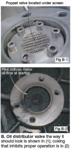
Embrace these procedures
Run on oil periodically. A key to firing oil reliability when it is needed: Operate on liquid fuel regularly—as often as weekly perhaps—if the OEM (original equipment manufacturer) suggests that frequency. For units in cycling service, consider transferring to liquid fuel on unit shutdown—either at low load or full-speed no load.
Operators of engines in continuous service, have to weigh the risks of attempting transfers to liquid fuel. Verify check valve operation.
Improve reliability by implementing a check-valve test procedure that verifies, before installation of every valve, both the proper cracking pressure in the forward flow direction and the absence of leakage flow in the reverse flow direction. Repeat this procedure regularly during the off-peak season and prior to winter operation.
Modifications to consider
Several mods are available to reduce coking after unit shutdown. These include:
- Implement a high-pressure nitrogen purge of the liquid fuel lines after the machine shuts down to eliminate residual fuel as a source of coke formation. A simple purge system can be installed and operated manually, or it can be automated with some integration into the control system.
- Change controls logic to allow operation of the A/A compressor after unit shutdown to help cool the fuel-nozzle components and reduce the probability of coking. Air flow can continue for a fixed time period or until the nozzle cools to some predetermined temperature. Another way to reduce component temperature is to increase ventilation air flow in the turbine compartment. This helps prevent coking in the uppermost cans, where it is most likely to occur. Measurement of air and component surface temperatures in the compartment will reveal where inadequate cooling exists and where additional cooling air must be directed.
- Two more ideas to improve cooling: Some operators have had success keeping fuel lines cool by wrapping them with cooling water coils and then covering the coils with insulation. Others are testing recently introduced water-cooled check valves.
- Early identification of nozzle plugging. A modification to the liquid fuel system that promises early indication of nozzle plugging is active monitoring of distillate pressure to each combustion can. When coke or unfiltered debris plugs liquid nozzles, pressure increases in the fuel line. If a significant reduction in oil flow to a particular can occurs, it quickly creates a pressure imbalance between adjacent combustion chambers.
In some cases, the continuous flow of combustion products through the cross-fire tubes can occur. Once cross-firing begins, it often is too late to prevent burning or melting of the cross-fire tube and liner, as well as the deposition of molten metal on hot-gas-path components. Such an event can be identified by a high exhaust-temperature spread, but it can be detected faster by continuous monitoring of fuel pressures to each combustion chamber. By establishing a suitable threshold for the allowable pressure differential on adjacent cans, hardware damage can be prevented.

Another important consideration when evaluating the use of alternative fuels is the presence of contaminants.
The processes and raw materials used to produce various alternative fuels can result in undesirable constituents in the fuel gas—including particulates, liquids, trace metals, and sulfur. In all cases, the turbine OEM’s fuel specification is your bible.
Particulates, which can erode components or plug fuel nozzles, usually are captured by standard filters (Fig 3). Liquid removal is handled by liquid separators and heaters commonly found on natural gas systems. Depending on fuel characteristics, either or both may be required on alternative gas applications.
Trace metals can cause major problems—specifically high-temperature corrosion of hot-gas-path components—and must be removed upstream of the GT. It also is important to remove sulfur— especially if a heat-recovery steam generator is installed behind the GT. It can cause corrosion at the rear of the HRSG if temperatures drop below the sulfuric acid dew point. On units with selective catalytic reduction systems, sulfur can react with free ammonia to form corrosive deposits and compromise the effectiveness of finned tube bundles.
Fig 4 illustrates a system suitable for fuel blending when the changes in MWI are moderate— that is, when the existing piping and manifolds can accommodate the blended gas flow. It describes a standard diffusion combustor system using steam injection for NOx control. The two fuel streams are blended using one or more mixing valves upstream of the existing gas conditioning equipment. Latter includes a knock-out drum for liquid removal, fuel heater, and particulate filter. Other contaminants must be removed upstream of this location.

The existing stop and control valves are used for regulating the flow of the mixture. As noted earlier, the degree of MWI variation determines what modifications to valve trim and/or fuel-nozzle orifices are required. Additionally, the fuel temperature setpoint also may be adjusted to achieve the desired range of MWI or to tune the MWI for varying heating value during operation. An inert purge system is shown, the use of which would depend on the specific composition of the fuel blend.
4. Conversion to low-Btu gas
Discussion to this point has focused on blending of alternative fuels with natural gas that can be accommodated with minor, if any, modifications to existing fuel and combustion systems. At the far end of the alternative-fuel spectrum is the use of low-Btu fuels produced from the gasification of coal or petroleum coke. The economics of converting a combined-cycle plant from pipeline natural gas to one with an integral coal-gasification system were presented in “Time to reconsider the gasification option” COMBINED CYCLE Journal, Spring 2004.
Low-Btu fuels typically contain high percentages of both hydrogen and carbon monoxide and relatively little methane, the primary constituent of natural gas (fuel 8 in the table).
Extensive modifications are required to convert from natural to low-Btu gas as the primary fuel. The volumetric flow rate can be as much as four to five times that for a natural-gas combustion system. In addition, diluent injection for NOx reduction typically is equal to or greater than the fuel flow. The increase in total turbine flow resulting from these two factors requires virtually all systems from the gas stop valve through the first-stage nozzle to be redesigned and replaced.
The new first-stage nozzle requires a sufficiently large flow area to keep the compressor discharge pressure from exceeding design limits. Likewise, to maintain acceptable pressure drop through the combustion system, the increased fuel and diluent flows require larger fuel nozzles and new combustors of larger diameter. Low-Btu fuels dictate diffusion-type combustion systems primarily because of their high hydrogen content. If the combustor is being changed from a DLN system, emissions requirements may dictate the installation of an SCR in the exhaust system to achieve permitted NOx levels.
Low-Btu fuel is not suitable for startup or shutdown operations, so a conventional fuel—either natural gas or distillate— is required as a startup/ backup fuel. If natural gas is used, then dual-gas fuel nozzles are required. Fig 5 shows a schematic of one such system that might be used with low-Btu fuel.

Dual-gas fuel nozzles have two sets of fuel passages and discharge orifices. Two separate and parallel fuel control systems also are required, one for each fuel stream. The existing fuel piping, valves, and manifolds would serve the natural-gas circuit, while new and larger-diameter piping, valve skid, and manifolds are needed for the low-Btu fuel.
Both an air purge and inert purge system are required as well. During operation, the air purge, supplied from the compressor discharge, flows through the fuel system not in use. The inert purge is for sweeping the low-Btu fuel from the system after shutdown. Lastly, turbineenclosure modifications probably are necessary, both to enlarge the space to accommodate the larger fuel manifolds, as well as for upgraded fire and hazardous-gas detection systems. CCJ OH