

Supply chain woes converge with lingering and emergent issues
If you have an HA (7HA or 9HA) machine in your future–close to 70 worldwide are in the pre-COD (commercial operating date) phase–and you haven’t already, now’s the time to get engaged with the folks who have been operating 110 of those units globally. And the best, and only, place to do that is by attending the HA Users Group Annual Conference, where over 100 users collaborate among themselves (and through membership in www.powerusers.org), vendors actively supporting the fleet, and with GE Vernova (GEV) to solve problems.
Why now? Because you are likely to experience many of the same issues associated with these machines since they were first introduced to the industry in 2016. As both the user and vendor material from last year’s conference reveals, despite progress being made on many fronts, several of the major, and original, issues still lack consensus on a root cause and what could be labeled a “permanent” or long-term solution.
Compounding the situation is that the advanced-class GT industry in the aggregate has been facing global supply chain disruptions; deficiencies in skilled and trained labor for shop and site work; constraints on sharing information because of confidentiality agreements between user and vendor; and general frustrations among vendors, users and insurers.
Easiest way to access the material you’re going to need on your HA unit journey is to become a member of the Power Users Group (www.powerusers.org), all of whom have access to HA User Group conference content posted at the site. GEV-related material is only accessible through the customer portal platform.
However, the most valuable information you’ll access is through the private conversations and user-only discussions following the slide presentations at the conference. The rule of thumb these days is the value of content is inversely proportional to the number of people who might see it. The 2025 edition will take place in Greenville, SC, from August 4-8 and you can register at this link.
2025 HA Users Group Steering Committee
Chair: Jennifer Scharfe, Florida Power & Light
Javier Badillo, NAES
Chris Bates, NAES
Mike Cashon, TVA
Jeff Klier, Constellation Energy
Rama Krishna, Sharjah Hamriyah O&M Co
Meredith Neal, TVA
Anner Reyes, CAMS
In abiding by today’s confidentiality restrictions, what follows here are only highlights of what went down at the conference.
HA evolution
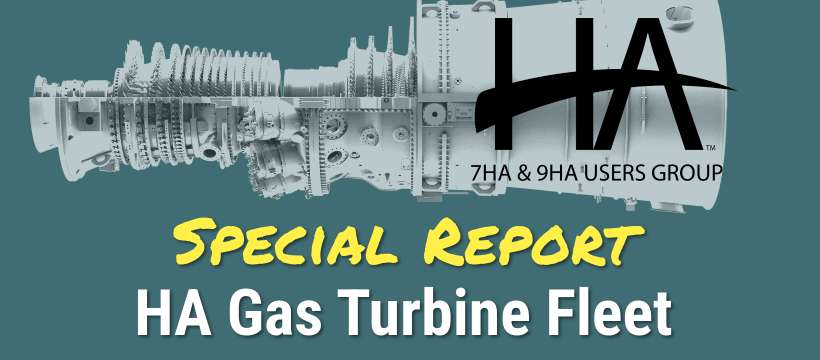
A late-1970s hit song by Talking Heads repeatedly asks the question, “how did I get here?” In a context-setting slide deck, one user representative and GE specialists reconstruct the evolution of the HA fleet from the 7FA.05 compressor, said to be the foundation of the HA design, to the latest models 9HA.02 and 7HA.03. Most of the machines operating or on order are of the 7HA.02 variety, but each of the units is related to the previous model.
For example, the newest 7HA.03 machine has more in common with the 9HA.02 version of the HAs than the 7HA.02, meaning the international user community has more to learn from each other than with the 7F and 9F users. One critical table in the slide deck compares the relevant design/performance data from the 7FA.04 and 9FA.03 through the 7HA.03 and 9HA.02 (Fig 1).
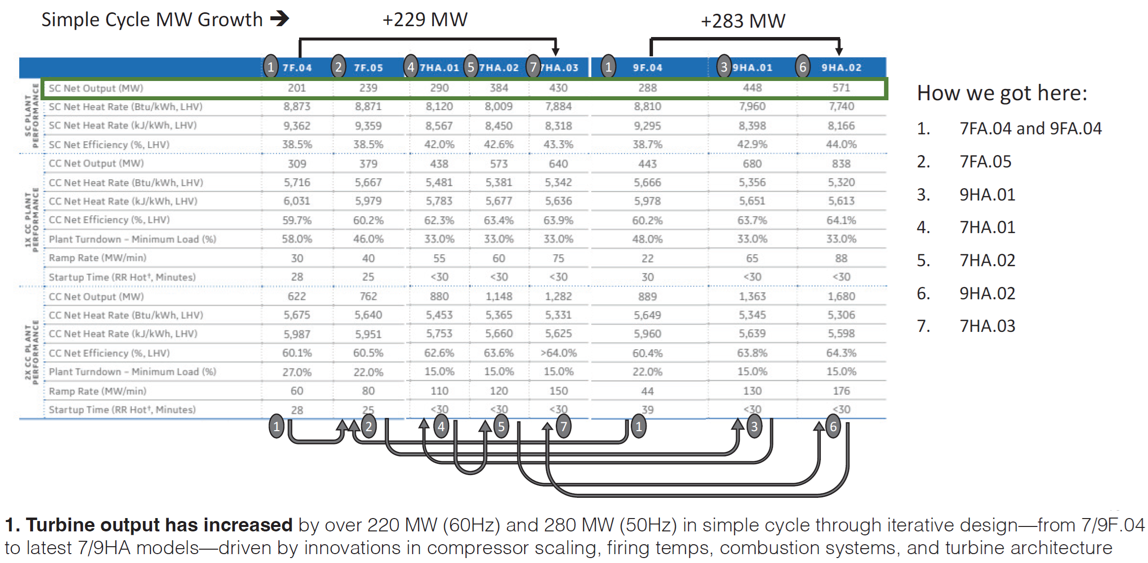
One fascinating tidbit from these slides is that 100 HA units were on order only four years after the first 9HA was shipped, and less than two years after the fleet leader 7HA unit began operating (Fig 2). Clearly, owner/operators were not taking a “wait and see” attitude before ordering. At the time of the conference, the HA product line had amassed 2.5-million operating hours.
One important distinction made here is between the 7HA.02 (FL16) and the 7HA.02 (FL18), the latter having a double-wall compressor, provisions for stage 4 blade cooling, higher firing temperature, and tighter HGP clearances, among other differences.
Flex hose failures
One of the most significant learnings at the conference was that two 7HA.02 machines at different customer sites had experienced premature failures of inlet bleed heat (IBH) flex pipe/hoses. These failures occurred on the “dog legged” style design that was made available in 2022 after an “angular hose” design failed in the field the prior year. One user reported that the failure occurred after only 10,169 fired hours in July 2023 while the machine was running baseload. It took seven days to return the unit to service using on-site spares, available because of operating history with leaks. This site now plans to replace these hoses every 10k hours.
Ten months later, the second user experienced an IBH flex pipe failure (also at baseload) after approximately 16,000 fired hours and 52 starts. Both sites have expanded the safety perimeter around the machine to protect workers. After the second customer failure, GE revised the safety related recommendations in TIL 2299 based on the debris range and by urging from the customers impacted. Both customers urged the community to take a hard stance on an employee exclusion zone to protect employees.
GE’s diagnosis is that the failure likely occurred from stress corrosion cracking initiated by sulfur attack (at a point experiencing higher stress than the rest of the hose), noting that one site was adjacent to a wastewater treatment plant where sulfur compounds could be present. However, the slide notes that, while the other site was not near a wastewater plant, corrosive compounds are “in the air.”
GE continues to investigate the IBH hose failure root cause with customer hardware cut ups and data collected on an operating unit at one of the failed hose sites. GE found higher temperatures and believes this also contributed to the problem. TILs related to this problem are different for different models of HA. Users should watch for revisions to TILs 2299, 2354 and 2341 in 2025.
Common fleet issues
Conference goers were also treated to the results of an attendee survey, which will help those just embarking on the HA journey understand what they should be looking for and asking questions about. The HA user group steering committee uses this real time survey tool to prompt conversation and collaboration throughout the conference duration. This creates an engagement among the users and impromptu sharing of “war story” as well as opportunities to learn from the most veteran operators of these newest technology machines.
The results, reported here as general HA user experiences, must be understood with respect to the HA design evolution described above. Machine design characteristics vary, each site has responded to the various TILs in its own way, and the condition of every unit (following COD) depends on the operating modes (e.g., fired operating hours, starts, ramp rates, etc.) and O&M practices at each site.
Of the respondents, 44 were attending for the first time, while 39 are veterans of the conference. Five represent HA.01 machines, 62 HA.02, 11 HA.03, nine 9HA.01 and one 9HA.02. 66% are units in multi-shaft CCs, 25% in single-shaft CCs, and 9% simple cycle. When asked what their major concerns are, the attendees listed parts, HGP, rotor, and vibration most often.
Other relevant survey results:
- 16% of respondents have experienced a rotor swap, nine have access to a spare rotor, and twenty-five wish they did
- 34% have experienced a forced outage (FO) of some sort, and 16% have experienced an outage resulting from foreign (or domestic) object damage
- 19 respondents have experienced stator vane rubbing, though 47 have not
- 34 have found loose or missing hardware in combustion assemblies, 33 have not
- Nine have swapped load frequency control (LFC) modules and the units are now load-limited
- 30 have observed the thermal barrier coating (TBC) eroding away on the GT blades (buckets)
- Nine have installed filters attached to the S1N cooling circuit and 32 others want them or need them
- 33 have experienced unibody spallation and have had to replace hardware early
- Six have experienced combustor inner diffuser cone (IDC) creep and 33 believe they will soon
- 52 have applied the TIL for the spacer 0 issue, six have a cracked spacer 0, fifteen have installed the rim seal (shim), and six are not happy with the shim
- Four have applied the phase 1 HPPS (high pressure packing seal) modification of the mid-shaft seal, 16 have applied the phase 2B HPPS and AIS (aft inducer seal) modification, and nine have noticed a reduction in MW output with the new seals
- 23 have measured excessive T2 vibration and 12 see it elevated past the first critical, 30 experience excessive T2 vibration run-to-run variation, 18 have generator frame resonance, eight require frequent re-alignment, and three experience large mid-shaft runouts
- Many have experienced numerous problems with journal bearings and thrust bearings
Attendees were also asked about GEV’s collaboration with the users during the conference and they did not grade on the curve. Forty gave the vendor a grade of C or below, 23 three gave a B, and one gave an A. While numerous specific short, often pithy and witty, comments were also offered, common themes appeared to be more transparency, desperation for spare parts, and slow response times to issues.
7HA.02 fleet leader outage observations
Staff affiliated with an early 7HA.02 site, along with a life assessment consultant, reported observations on one unit there following a spring 2024 major inspection (MI) outage. Unit had over 48K hours and 162 starts. Worth noting is that the unit’s original rotor was exchanged in 2021 for a refurbished rotor with 9K fired hours and 90 fired starts.
The slides offer a detailed account of findings, especially as each relates to respective TILs and GEKs, while noting that there are approximately 75 TILs associated with the GT, generator, and controls.
The high-level summary of the experience notes a lack of spare parts, variations in the engineering and technical dispositions from GEV, lack of rotor inspection accuracy relative to the TILs and GEKs, lack of skilled labor force expertise and planning, and gaps in tooling delivery and schedule integration. One slide notes that in some instances, the site had to settle for the “best of the worst” refurbished used parts available, likening it to having to maintain an HA junkyard for spares.
In addition, site staff posed significant challenges to GEV’s interpretation of findings, observations, and remedies. Generally, it was noted that engineering responses are based on fleet data/knowledge and/or a perception of the customer’s risk profile, parts availability, contract budget, liquidated damages, or access to available resources for remedies.
Specific machine observations listed are:
- Pitting on the inlet guide vanes (IGVs), variable guide vanes (VGVs), stator vanes, and rotor blades
- Deformed stator vane ring horizontal joint keys (TIL2135)
- Stator vane ring segment tab wear (TIL2333-R1)
- S1S TBC rubs and flaking (TIL2141)
- Stage 1 buckets TBC spallation and airfoil leading-edge region through-wall holes
- No cracks in the spacer 0 rim (shim install)
- Generator stator greasing, loose laminations
- GT and generator rotor and GT stator casing magnetism
9HA.01 fleet leader MI results
A user representing an early 9HA.01 site reported findings at the 2024 major MI point. Short history of the unit includes an unplanned outage for an S1B replacement (2018), HGP major with a 72-day outage to rectify the shaft line vibration issue (2020), T fairing and spacer 0 correction and a 23-day outage extension (2023), and an MI following an forced outage (FO) beginning in May 2024 and scheduled through January 2025.
Spacer 0 crack migration was observed on the GT rotor, reminiscent of 2023 spacer 0 findings. As there was no new spacer 0 replacement available, the site opted for installing the shim to close the gap between the spacer 0 and wheel 1.
Site also plans to migrate from the FL15 to the FL21 rotor design which reportedly addresses concerns enumerated in TILs 2244-R1 (T fairing distress), 2277 (compressor blade retention ring), 2330 (phase 2B seal package), 2147 (rotor life limit), 2445 (turbine rotor space 0 inspection), and 2333 (turbine cover plate inspection). Slides note that the compressor discharge casing (CDC) requires trimming for the FL21 rotor assembly.
Combustor hardware impacts include hula seals burned or missing on seven of 16 nozzles in the fuel nozzle and cap assemblies, large cracks in the fuel nozzle casing, fretting of the flow sleeve piston ring grooves with loss of material (in the context of combustion dynamics), degraded combustor parts on junction links and cracks on some casings, large internal crack on a transition piece (TP) replaced in 2019, and TP side seal missing one year after an MI.
Finally, distress was noted on the compressor stator vane (TIL2322), resulting in a stage 9 upgrade to the exit guide vanes (EGV), which, the slide emphasizes, is still the “former” design, not the rings necessitated by the TIL.
Steam-turbine rotor defects were described. For the intermediate-pressure module (IP) – heavy rubbing of bucket tips, two locking blades heavily twisted and exhibiting shingling, several locking blades twisted out of spec, and missing J seal. No root cause has been determined and the rotors has been deemed not returnable to service as-is. For the high-pressure module (HP) – heavy rubbing and gaps at tip of buckets and rubbing increasing over time. Again, no return to service as-is.
Operational issues
An HA.02 site reported on general operational issues and steam turbine defects. Unit 1 at the site had 45K hours and 201 starts, unit 2 had 21K hours and 131 starts. In May 2023, unit 1 experienced a GT trip and took a forced outage following a BI. Vibration of the No. 2 bearing was greater than 1 in/sec accompanied by a sudden shaft phase change. Subsequent finding was the GT spacer 0 (covered in TIL2445R1) liberated, caused by high cycle fatigue (HCF). The unit was out of service for four months.
The site purchased and installed a new rotor (non LTSA), and replaced S1N, S1B, S1S, S2B, and S2S and plans to install the CAPA (corrective action, preventive action) kit during the 2025 MI. Report notes that there was no backup stock of rotors from GE, hot gas path (HGP) parts were in short supply, and the consumables took a few months to arrive.
Site also experienced combustion spread deviation alarms when the axial fuel staging (AFS) circuit was activated. Suspected cause was a V-shaped wire from a damaged gasket on the compressor discharge casing and a thin plate emanating from the unibody seal, both depositing in the combustor area.
Regarding the steam turbine, the last stage blades were Stellite-coated to mitigate erosion, moisture was absorbed into lube oil (caused by errant steam flow during startup while the oil condition monitoring system was working poorly), and the site plants to change out the main condenser tubes because of excessive leakage.
An LNG-fired 9HA.01 site operating between 15-100% load range with very low annual starts reported a forced outage for an S1B replacement in 2019, a planned outage to correct combustion wear on the piston rings in 2022 (which had earlier led to a forced outage), and two trips in 2021 and one in 2022.
During an MI in 2021, the site found several dropout nuts on the floor of the GT enclosure and several vertical flange bolts between the exhaust frame and diffuser. When personnel opened the sealing bracket, they found several failed metal plates and insulation. Subsequent borescope inspection (BI) indicated cracks and missing plates at every airfoil. Site also reports that GE is recommending replacing the entire exhaust frame with the new design but has not yet released it. The site prefers to repair it rather than replace.
Highlights from a more recent 9HA.01 installation with three gas turbines (natural gas with diesel fuel backup) include: (1) diesel fuel firing has been problematic in one GT since COD; liquid fuel combustors have been replaced, but GE is not sure how to correct; (2) frequent foundation fieldbus issues and loss of communication to the control room; (3) purge valve and digital valve positioner (with air conditioning) failures; ((4) random hot air leaks from GT piping flanges inside the enclosure; (5) failure of valve positioners in the GT compartment; and (6) recent failure of a steam turbine low-pressure admission control valve.
While the first combustor inspection (CI) on one unit was successfully completed, GE’s support with respect to manpower, parts, and tools was “questionable.” Other comments include GE completely ignored cybersecurity during commissioning of the controls and monitoring systems, and the DCS prematurely reached the end of “extended support.” At conference time, the plant continued to run primarily on gas only while liquid fuel (LF) issues of one GT was yet to be resolved.
Vendors to the rescue
Several vendor presentations were interspersed throughout the user-led discussions, many of which featured collaborative experiences between users and solution providers. As the HA fleet expands, so too does the network of third-party vendors supporting it. The user community has shown a growing openness to these partners, particularly when it comes to resolving long-standing operational challenges.
A prime example: vendors like Cutsforth have been addressing collector ring issues on SPL generator frames for years, and the majority of 7HA.02 users have now adopted a vendor solution for A042 leak containment.
The HA steering committee received more presentation proposals than they could accommodate for the 2024 conference. They carefully selected vendor presentations that addressed common fleet-wide challenges, emphasizing solutions-oriented content while screening out those with a “sales pitch” tone. The summaries that follow offer brief overviews; for full slide decks, visit www.powerusers.org.
Back to basics – generator testing
Jamie Clark – AGT Services
This roundup covers standard electrical, mechanical, and visual tests and inspections for large generators, with examples of bad vs good test results, what sub-components to inspect, and recommended corrective actions. Included are Kelvin Bridge/DLRO (digital low-resistance Ohmmeter) for winding resistance, Megger for insulation resistance and polarization index, DC leakage for controlled over-voltage (including the IEEE95 Appendix A graded method), HiPot for high voltage, electromagnetic core imperfection detector (El CID), and bump test for end winding resonance frequency. More specialized stator tests include surge, partial discharge, corona camera, AC HiPot, EMI, robotic inspection, acoustic surveys, AC impedance, pole balance, and shorted turn test. A fun but instructive highlight is understanding why tuning end-windings is like playing the guitar.
Pro-active SCR/CO system management for lower emissions and operating costs
Andy Toback – Environex Inc
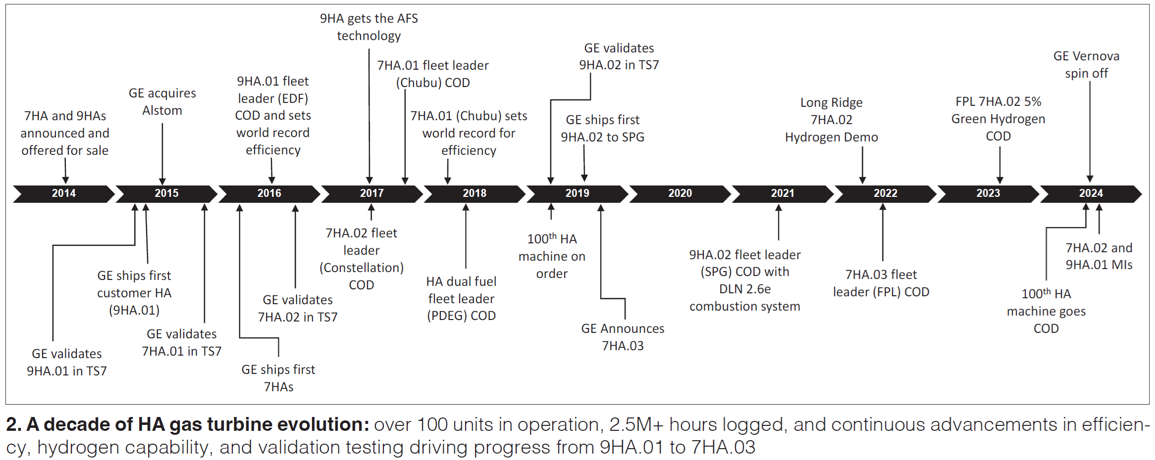
Factors affecting SCR system performance include non-uniform gas and reagent flows and temperatures, catalyst deterioration, and certain plant O&M factors. Photos show examples of ammonia grid deposits, CO catalyst pressure damage, brick shifting (common with extruded ceramic catalyst), and other maladies. Regular cleaning of the ammonia injection grid (AIG), catalyst surfaces, and ammonia salt deposits from the economizer will maintain good backpressure levels and save you a substantial amount of money relative to the cost of cleaning (Fig 3).
Complete cycle solutions for all GE H-class plants
Pierre Ansmann and Norman Gagnon – Arnold Group
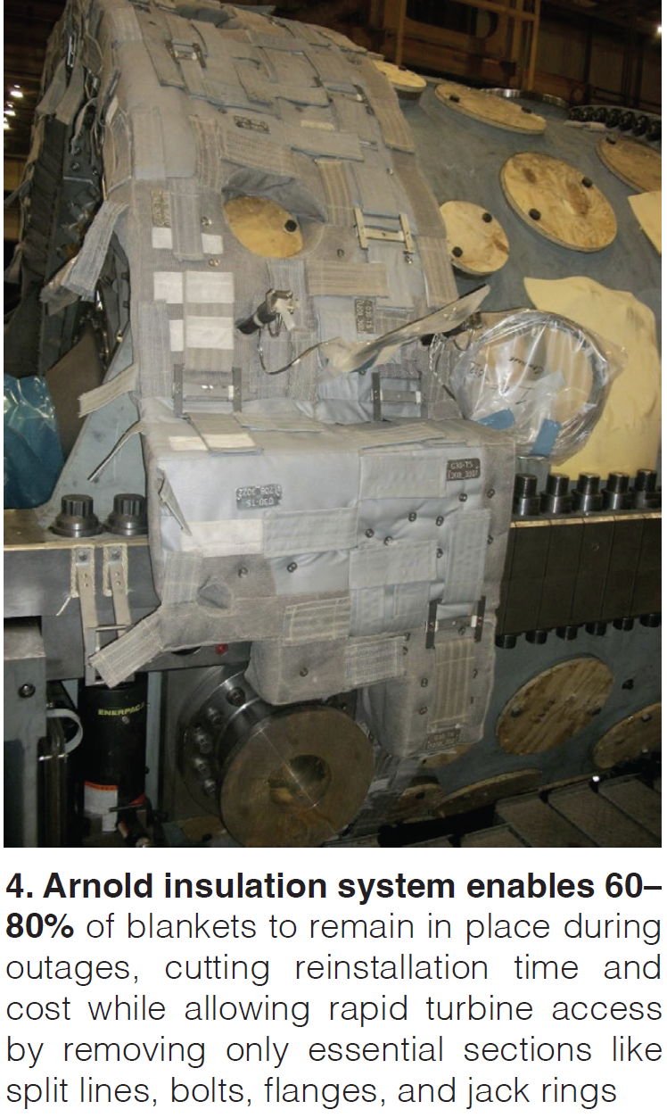
Slides focus on the design and benefits of state-of-the-art insulation and warming systems for gas and steam turbines and, with EPRI funding, field testing results from latest warming and insulation system designs for HRSGs. D11 steam turbine case study reveals a start-time reduction from 266 to 149 minutes and 25% lower high-pressure (HP) rotor low cycle fatigue life consumption, along with attendant improvements in emissions and fuel consumption. A 250-MW unit will require a max of ~200 kW parasitic power and ~50 kW to maintain temperatures at shutdown. Install times are ~30 days.
Results from testing HP evaporator downcomer heating blankets at Duke Energy’s Buck facility Unit 12 showed (1) that HP drum pressure could be maintained at 20 psig for several hours, (2) lower tube temperature differentials, and (3) no large quenches or shocks during startup compared to the unheated Unit 11. There were extenuating circumstances typical of a field test, such as issues with instrumentation and components not built to commercial specs. Warming could be an alternative to steam sparging for reducing stress on pressure parts, but a large, dedicated power source would be required. Total install time is estimated to be 3-5 days with a 300-kW maximum power need, and ~100 kW to maintain temperatures at shutdown.
Accompanying photos and 3-D renderings show all aspects of insulation and warming system design including insulation thickness, support structures, joints and attachments, blanket shapes, blanket materials, and thermocouples. Commercial installations would require use of Arnold field services for removal, inspection, and re-installing insulation and heating elements to maintain warranty. Note that many of the 9H and newer 7H units come equipped with such systems because of superior quality and maintenance benefits (Fig 4).
HVTS for casing corrosion mitigation
Eric Duvekot – Integrated Global Services
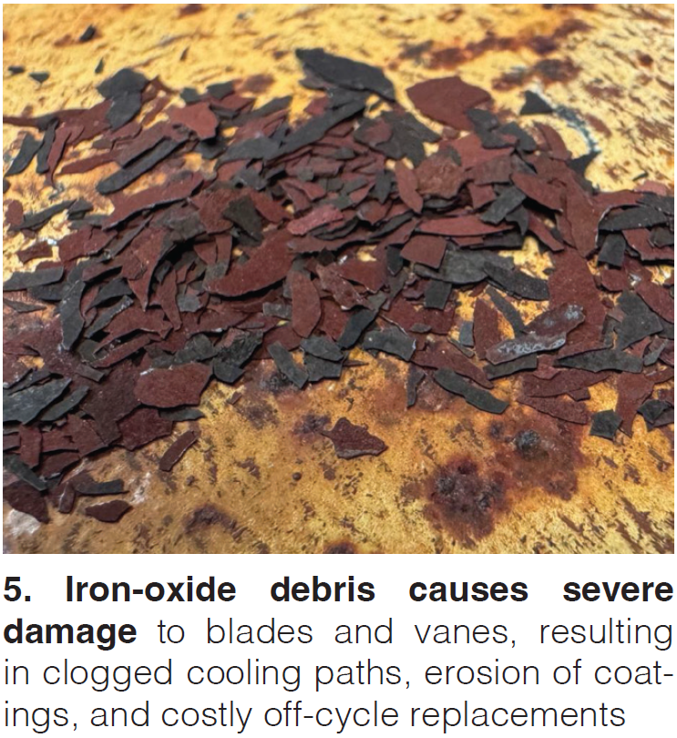
A proprietary superalloy applied using a high velocity thermal spray (HVTS) has shown to be effective in mitigating the flaking and spalling from unprotected low-chrome surfaces exposed to high-temperature oxidation in the compressor and combustion regions of the turbine. This debris damages fixed and rotating gas turbine (GT) components, plugs cooling passages, and erodes thermal barrier coatings (Fig 5). The material can be applied on-site in 6-10 days in a temporary, completely enclosed space. Since 2022, 11 GTs of various frames and outage configurations in baseload and peaking service have been clad, with subsequent borescope and IGS eddy current inspections showing zero coating degradation.
Vibration information – more is better!
Chuck Requet – Cutsforth and Meredith Neal – TVA
These two companies have partnered to apply wireless vibration sensors, data collection, and analysis (using Cutsforth’s InsightCM platform with “industry standard” viewers) first at TVA’s nuclear plants, and now at eight CC plants and one simple cycle plant. Case studies from the nuclear plants include a gland seal exhaust fan and bus duct cooling fans. Objective is to use data from the wireless system acquired every eight hours to prompt off-cycle data collection from handheld devices when warranted. Wireless can reduce the install cost of vibration monitoring by up to 70% for a large fleet deployment (35,000 sensors) and cut the break-even point by half.
Oh no! Turbine part damage – RCA planning and thoughts
Matthew Ferslew, Structural Integrity Associates
So, you’ve observed damage or failure of one or more GT components. What do you do next? Obviously, that’s complicated and very site- and component-specific, but this set of slides guides you along the trajectory towards answers. One critical situation to avoid is the root cause analysis (RCA) process “owner,” or the individual/company controlling the “story,” having an “agenda.” Slides are very detailed and packed with useful information, especially for those who are not materials specialists.
Critical actions for site personnel include making sure hardware under RCA is in your possession, and not lost or damaged; collecting data and alarm trip logs from the controller before they become archived or otherwise difficult to access, or disappear; taking photos of as-found components after disassembly; talking to outage craft team members who may recall unusual observations; and taking extreme care in preparing the affected components for shipping. Section on “metallurgical and damage mechanisms and inspection/observation 101” includes slides on fatigue; creep; dwell time fatigue; overload/tensile strength; wear, erosion, and fretting; corrosion and oxidation; and embrittlement and crack propagation.
- A 7HA CC unit can lose close to $250,000 annually with every inch (water column) of higher backpressure in the GT exhaust back end
- Key RCA steps, items, and actions begin with damage observations and ends with verification of the corrective actions taken
Nice to meet you. The first-ever vendor fair for the HA fleet was held in a small, focused setting that fostered meaningful conversations between users and solution providers. Vendors were hand-selected from a highly competitive pool of applicants, as interest exceeded available space. Feedback from participants was overwhelmingly positive—more than half indicated they plan to engage with a vendor as a result of the fair. Encouraged by its success, the HA steering committee will make the vendor fair a regular feature of future conferences, with plans to expand both the capacity and the diversity of offerings for the growing HA user community.
Customer-centric approach leads to marked enhancements across HA fleet
Taking the stage on Thursday of the 2024 conference, GE Vernova reiterated sharpened focus on customer-driven innovation and operational excellence across its HA gas turbine fleet. The company presented a comprehensive update showcasing fleet performance gains, product improvements, and strategic investments aimed at meeting surging global demand. GEV highlighted notable strides in availability and reliability metrics, bolstered by a 60% expansion in rotor repair capacity and shorter repair cycle times—direct results of targeted supply chain enhancements. The company also addressed user priorities head-on, unveiling a new HA Fleet RCA Dashboard for greater transparency and rolling out advanced solutions for known issues like vibration, S1N distress, and thrust bearing loads. From hardware durability to software insights and global shop expansions, GEV’s message was clear: it is leveraging customer input and data-driven analysis to elevate the performance, reliability, and responsiveness of its gas turbine technology at scale.
As of the 2024 conference, GE Vernova (GEV) reported the cumulative sale of approximately 164 HA gas turbines, with 104 units in commercial operation. With the current GT demand boom, expect a significant jump in these numbers over the next few years. The HA fleet has collectively amassed over 2.6 million operating hours, the clear front-runner in the advanced-class GT fleet.
The 7HA fleet achieved availability of about 92.12% and reliability of around 97.76%, while the 9HA fleet reached approximately 92.89% availability and an estimated 98.91% reliability—both showing marked improvement since the last conference due to resolved engineering challenges.
Supply chain and shop capacity expansion
GEV strives to prioritize customer feedback and reporting to help improve its products. Since their first conference appearance in 2019, GEV has taken and is continuously taking steps to improve their HA units based on customer feedback and data.
During a presentation and Q&A session with Shane Long, VP of global supply chain, he addressed continued support to its customers as a standalone entity and highlighted some of the marked improvements to both 7HA and 9HA units over the last five years.
Notably, there has been ~60% increase in rotor repair capacity and around 30% reduction in repair cycle times, with ongoing efforts to enhance these metrics further. Upward trends in these areas are due to substantial investments in the global supply chain in response to user concerns.
Long also noted an upward trend in HA HGP growth for buckets, nozzles, and shrouds from 2022 onward. A concerted effort in fine-tuning operations for over 90% of these hot gas path components across 10 lean lines has resulted in about a 24% increase in turbine output year over year. This trend is projected to continue into 2025.
In addition, combustion and HGP hardware repair cycles have decreased from 12–15 months to approximately six months for most components. Coated hardware repairs still require 9–12 months, with a pathway and goal noted to achieve six-month repair cycle in the future.
Global signs of growth. As part of the presentation, Long also discussed growth trends in various locations across the globe. In Greenville, the OEM is working toward increasing capacity, and in Singapore, they’re expanding their shop by about 50%.
Globally, GEV is also ordering and staging additional hardware for HA rotor enhancements and qualifying new rotor forging suppliers for production and refurbishment needs. All of these efforts have helped streamline rotor repair cycles through lean processes.
RCAs
In 2023, GEV received feedback from several of its users looking for more frequent updates on fleet-wide root cause analysis. David Cihlar, GT product service manager, and David Boehmer, principal controls engineer, addressed customers’ voiced frustrations over a lack of visibility to RCA status and progress. Over the last year, the team has worked to mitigate some of these frustrations by creating an HA fleet dashboard, increasing visibility and transparency on the user side.
The team presented the HA Fleet RCA Dashboard to the audience, which summarized the status of the top gas turbine issues and tracks containment measures, RCA completion, CAPA implementation timelines, and relevant TILs.
In addition, GEV has created more opportunities to interact with its customers directly through recurring webinars and user conferences. Each format allows customers to ask the team questions, providing more clarity on certain topics while also helping the team address users’ needs for future development.
Vibration issues
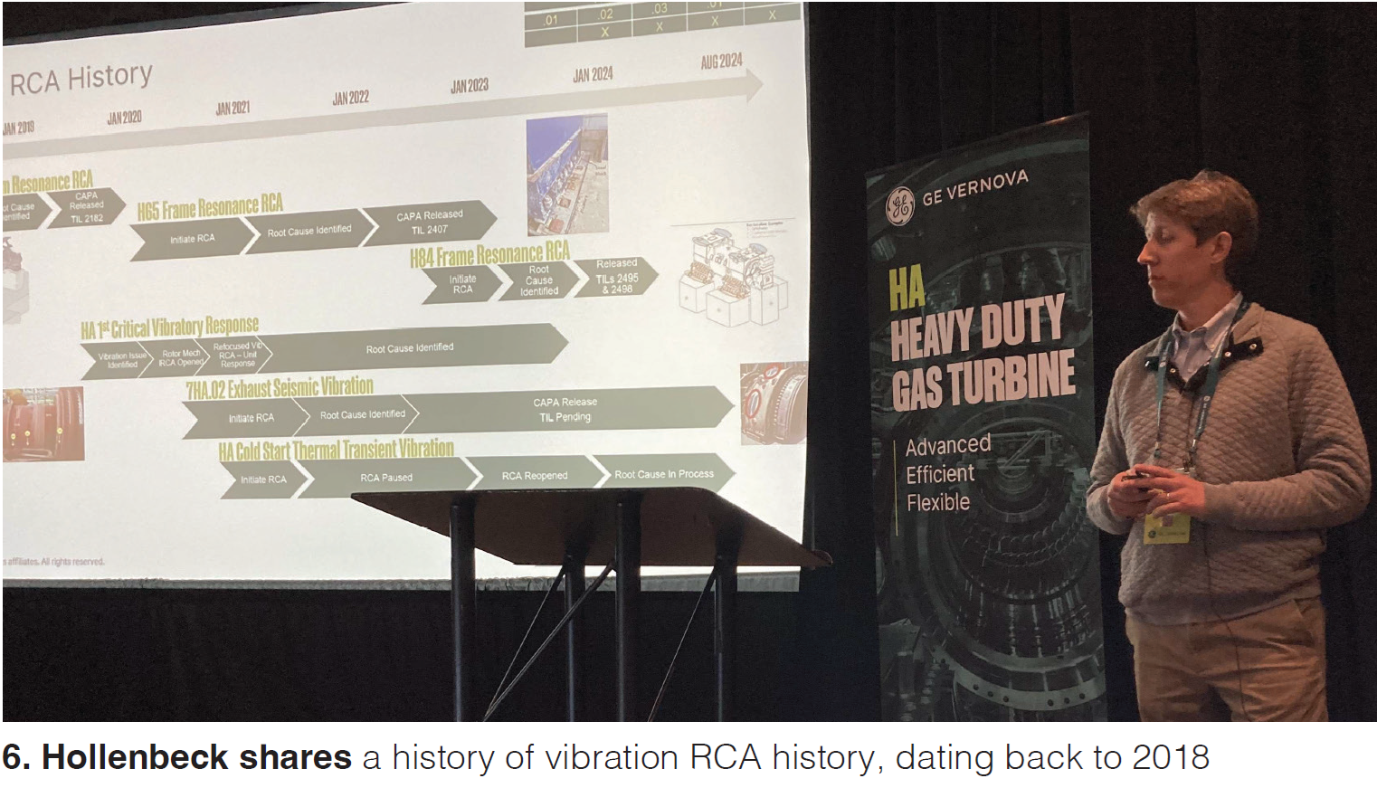
Jonathan Hollenbeck and Molli Dill of the power train dynamics and diagnostics team addressed vibration challenges related to system resonance in gas turbines and generators (Fig 6).
The team has been tracking various vibration RCAs since 2018 and implemented and communicated corrective actions to customers via TILs. Hollenbeck and Dill highlighted corrective and preventative actions addressing past concerns over 7HA.02 exhaust seismic vibrations. They found that transmissibility improved between 20-26% when ribs were installed to the fleet, further reducing seismic vibration by an average of 32%.
HA first vibratory response. The presentation also dove into the HA first vibratory response. Rounds of testing and customer data has indicated a higher Q factor in the 7HA.02 compared to the 7F.05. Findings point to lower rotor and oil film damping contribution, higher uncoupled stator/rotor eigenfrequency ratios, and gas turbine/foundation interface dynamic stiffness. Data suggests the change in first critical vibration amplitude tends to slow with continued operation, driven by rotor eccentricity. The corrective action for units currently in service is through, among other things, midspan balancing.
Cold start thermal peak vibration. HA cold start thermal peak vibration risk cost analysis was also outlined to conference goers. Hollenbeck and Dill demonstrated the effect of replacing the train load coupling in a 9HA.01 engine. The engineers were able to shift the turbine’s resonance mode away from its normal running speed, resulting in a reduction in thermal stress during cold starts.
This improvement, which increased the separation margin from the resonance frequency, had a positive impact on the turbine’s thermal response, reducing wear and enhancing overall reliability, especially during start- up conditions. This kind of enhancement helps the turbine run more smoothly, reduces the impact of thermal stresses, and potentially extends the life of the turbine.
S1N distress
Since 2019, customers have expressed ongoing challenges with S1N LE and TE distress in both 7HA.01/2 and 9HA.01/2 engines. The root cause was identified as excessive oxidation, leading to debris accumulation in cooling holes, especially in hot or humid climates. GEV teamed up with Florida Power & Light in 2019 to investigate this issue more closely. Jenn Scharfe, CT fleet team engineering leader for FPL joined GEV’s Clayton Greer, a GT product service lead engineer to present their findings and conclusions.
Throughout the course of the study, FPL and GEV tried various measures to prevent oxidation, including a rainbow test to determine effectiveness. The rainbow test concluded after 19k hours of operation in 2024 and led to new maintenance approaches. Corrective measures, including the addition of OD/ID filters, have proven effective and are now standard in all new and repaired hardware. Users were also advised to consider additional casing coatings and early inspections to prevent assembly gaps.
Dual-end drive (DED) collector
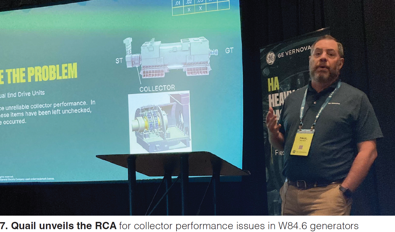
Across the W84.6 model generator fleet, some customers have identified collector performance issues, and unchecked units have experienced flashovers. GEV detailed RCA findings and discovered that key components in 7HA.02/3 gas turbines like carbon brushes, shunts, brush holders, and collector rings were contributing factors.
Addressing GEV’s initiative to identify and repair the W84.6 dual end drive units was Paul Quail, a generator rotor COE technical leader (Fig 7). The team noted three main findings in their root cause analysis: aerodynamic windage, brush track heating, and collector ring configuration.
Aerodynamic windage. GEV performed several validation tests and studies and concluded that aerodynamic windage, or lifting of the brushes, can lead to poor ring-to-brush contact. As such, a high ring surface speed can enable a high-pressure boundary layer. The team concluded that installing dual groove rings reduce the windage effects on the brushes; dual groove and slotted brushes provide better brush-to-ring contact, eliminating brush overheating and blue shuts and reducing selectivity to acceptable levels; using dual groove brushes is preferred since it does not require that brushes be re-slotted, thereby reducing maintenance.
Brush bouncing. GEV’s team of engineers investigated the root cause of brush bouncing, a phenomenon that occurs when insufficient or deteriorated collector ring film leads to the brushes breaking. A key driver in this is high collector ring temperatures, which can lead to their breakdown. To combat these issues, GEV’s technical experts ran through a series of validation tests and studies, and their root cause analysis pointed to brush track heating.
After running through tests, the team has made crucial discoveries and recommendations: A six- wide brush layout is more effective at heat distribution across the ring and brushes; and a lower brush track temperature is expected to retain film for longer based on promising preliminary data.
Brush vibration. Additionally, customers have noted a pattern of brush vibration in in their 7HA.02/03 units. Brush vibration affects stability and can lead to ring surface imperfections. The GEV team conducted test stand validation studies and thermal modeling simulations. They also conducted factory test vibration measurements and are currently analyzing site vibration measurements. Their findings led to the discovery of misaligned axial holes, which distorted collector rings.
GEV concluded that brush vibration and bouncing was caused by collector ring deformation from the axial cooling holes. Over time, the structure of the axial cooling holes can warp or shift from factors like change in temperature or mechanical stress, weakening the collector rings and relaxing the original shrink fit.
To address the cause of brush vibration, GEV reengineered the size and quantity of the cooling holes, moving them closer together to be less than the width of the brush. Doing so resulted in the collector rings becoming more compliant and enabled a reduction in its diameter. This change has shown to positively impact windage and brush track temperature.
Ongoing corrective actions. Quail concluded the presentation by outlining the current status of corrective actions and next steps. So far, some of these measures have been implemented and have yielded positive results, but GEV is continuing to develop and test solutions, including a full-size collector test stand expected to be operational by 2025.
Thrust bearing challenges
Customers have observed higher-than-expected hot gas path thrust loads in some 7HA.02 units. Consulting engineer Will McEntaggart outlined GEV’s findings and the steps they’re continuing to take to mitigate future problems.
McEntaggart focused heavily on various operational and design factors and how they can impact forces acting on gas turbine thrust bearing and the synchro-self-shifting (SSS) clutch. Built to help manage thermal expansion and accommodate temperature-based shaft growth, some units were experiencing sliding SSS clutches. This change in motion, in conjunction with the forces from the unit’s steam turbine load, has added additional forces to the thrust bearing in some cases.
Additional factors. Other contributing factors affecting a unit’s thrust bearing capabilities were component alignment, gas turbine aero thrust load, and the condition of certain components like S1 nozzles and mid-section seals. Each of these parts interact with one another and influence the amount of force that the thrust bearing and SSS clutch experience while in operation.
Achieving temperature regulation. The GEV team is working diligently on corrective measures to alleviate thrust bearing challenges and regulate the unit temperature. All units will now alert users if the temperature rises above 105°F, helping to prevent further wear or damage.
Improved TC cable routing. Improvements have also been made in the fleet’s thermocouple cables, per TIL-2485. By adjusting the cable routing for more accurate temperature readings, customers can receive more reliable data. In turn, teams can use their findings to help maintain safer operational limits.
S1B Leading Edge Erosion
Some 7HA.02 units have experienced spallation of the thermal barrier coating (TBC) due to bonding issues. Clayton Greer delivered the presentation, highlighting GEV’s root cause analysis and corrective actions to improve the fleet’s overall durability.
Improving the bi-layer TBC system. Issues surrounding delamination and erosion of the bi-layer thermal barrier coatings were reported across multiple turbine models, particularly the 7HA.02 engines. Studies indicated that the root cause was from top-down exposure to high velocity gases and erodent materials.
As part of the initiative to improve the units, GEV made changes to the cooling hole clearing process, helping to ensure better airflow and temperature regulation. The new TBC technology is scheduled to be rolled out over time, with the 7HA.02 AGP turbines receiving the improvements first, followed by 7HA.02 non-AGP turbines in August 2024, and a full process cut-in expected by the beginning of 2025 for 7HA.02 AGP turbines.
GEV aims to create more resistance to erosion and delamination within the units by improving the bi-layer TBC system. For customers, this translates into better performance and a longer shelf life for their units.
What’s next for GEV
Diving into several root-cause analyses throughout the HA fleet over the past several years, the OEM has shown their dedication to improving their units for a global customer base. Considering customer feedback, the team has prioritized users’ most pressing needs and provides full transparency in their problem-solving solutions.
Looking to 2025
The user community stays in close contact with the HA steering committee—reaching out as they bring units online or to share valuable lessons learned from the field. The committee remains dedicated to amplifying user voices and offering support, especially when challenges feel overwhelming. While users consistently praise the high efficiency and robust performance of their HA machines, the size, complexity, and advanced technology of these units come with a learning curve that can be steep.
Looking ahead, the committee is already preparing the agenda for the 2025 HA Users Conference. In partnership with Power Users, this August 4-8 will undoubtedly be the largest and most impactful HA gathering to date. A major focus will be increasing transparency and collaboration, with more shared experience sessions featuring the OEM and vendor partners—highlighting real-world problem-solving and actionable insights.
To accommodate expanded content and deeper discussions, the committee is extending the conference from three to four days. The 2025 event takes place in Greenville, SC—GEV’s backyard—providing an ideal opportunity to attract both new and returning users operating all HA models from across the globe for a truly collaborative and solutions-driven experience. CCJ

