Air inlet systems—including filter houses, evaporative coolers, cooling-coil support structure, silencers, ductwork, etc—seldom get the respect they deserve. Properly maintained, they help assure maximum output and high availability of your gas turbines. Yet, they are almost an afterthought at many plants, the focus being primarily on rotating equipment.
Annual inspection of the air inlet system by plant personnel typically is recommended by owner/operator colleagues participating in discussion sessions on the subject at user-group meetings. Those discussions typically focus on air filtration alternatives and inlet cooling systems (evaporative coolers, foggers, chillers), paying minimal attention to the structural elements of the filter house and bellmouth.
Air inlet systems can be divided into four parts: (1) bellmouth or inlet scroll, (2) inlet plenum, (3) clean-air side, and (4) dirty-air side. It’s very important to inspect for coating failures on the carbon-steel surfaces within the filter house and plenum, and downstream to the bellmouth,
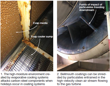
Rust, paint chips, and debris released on the clean-air side downstream of the filters (Fig 1), are swept along by the high-velocity air stream and can impact and damage critical components—such as the bellmouth (Fig 2) and compressor airfoils.
Corrosion can be a troublesome problem where filter houses are installed near wet cooling towers and/or when fogging systems are used for evaporative cooling. When corrective action is necessary, users should give special consideration to the outage window, degree of surface preparation, quality of the coating system specified, and the painting contractor’s qualifications and competency to maximize maintenance intervals.
Options for steel preparation are determined by the condition of the material and the existing coating system. Proven options, according to the experts at Taylor’s Industrial Coatings Inc (TIC), are (1) high-pressure water blasting with spot power tooling of severely corroded areas, and (2) grit-blasting.
OEM coating specifications typically call for an inorganic zinc primer, epoxy intermediate, and/or top coat. This is a respected coating system for shop-applied products—when done correctly. However, Troy Waters, TIC’s field superintendent, explained that zinc primers sometimes are not applied in accordance with the manufacturer’s instructions and may not maintain their integrity for the expected service life.
Reasons include the failure to (1) adhere to the manufacturer’s recommended 24-hr minimum recoat time, (2) remove loose zinc dust from fall out/overspray, and/or (3) take the extra step in promoting adhesion of the subsequent coat by screening the zinc prior to the epoxy intermediate or top-coat application.
To protect against delamination and corrosion, TIC created a proprietary coating system which it says has been validated in the harshest of environments—including coastal, high humidity, and highly polluted atmospheres.
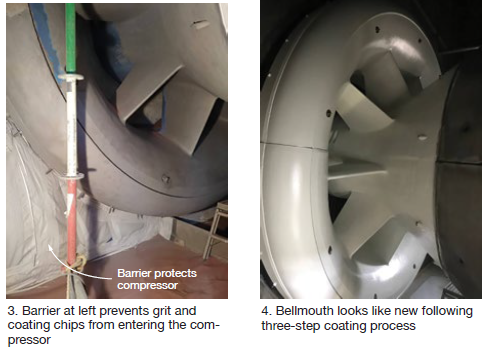
TIC’s management strongly recommends against recoating the bellmouth until inspections are performed upstream by its experts and they confirm the coating is well-adhered to metal surfaces. Were coating material to release into the air stream it could quickly compromise the new asset protection coating system downstream.
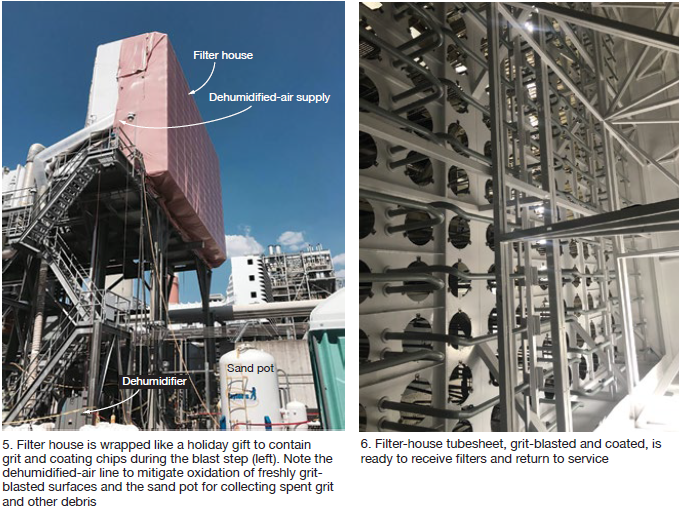
Figs 3-6 illustrate work by TIC personnel on the filter house of a 7FA about halfway through the engine’s nominal design life of 30 years. In this case, particles of rust and coating released from the bellmouth and upstream components were damaging the smooth profiles of airfoils, therefore reducing compressor efficiency.