O&M Clinic for Legacy GE Gas Turbine Users
Turbine Tip No. 13 by Dave Lucier, owner/GM, PAL Turbine Services, applies to General Electric package power plants (PPP), including Model Series 5001P, 6001, and 7001.
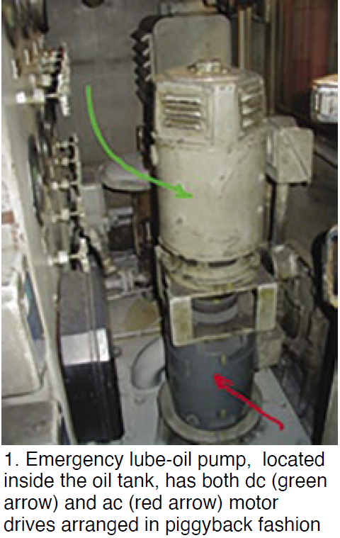 GE gas turbines are equipped with dc emergency lube-oil pumps (GE designate 88QE). This device is controlled at the motor control center (MCC) with a three-step starter circuit. In many GE configurations, the 88QE is coupled to the ac lube-oil pump (88QC) in a piggyback configuration (Fig 1). The dc motor (green arrow) is atop the ac (red arrow) motor. Below, a centrifugal pump (not shown) has its suction inside the 1800-gal (nominal) lube-oil tank.
Note that while this design was typical in legacy units, some owner/operators preferred two separate motors and pumps, because the interconnecting coupling had been known to fail on occasion.
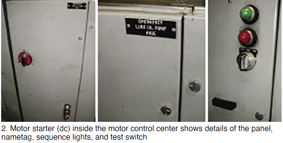
The dc motor starter is shown in Fig 2. Panel, nametag, sequence lights, and test switch are visible.
The system is designed to allow testing the 88QE motor starting sequence, which should be done regularly, whenever the gas turbine is operated at rated speed. It also can be tested when the generator is synchronized to the grid and under load.
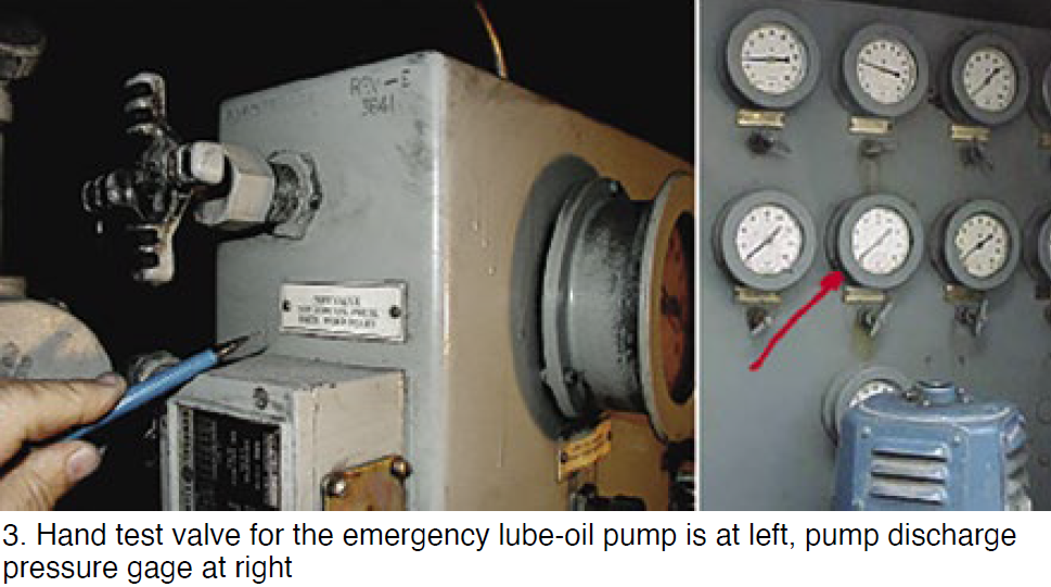
For example, with a GE Frame 5 at 5100 rpm, a reliability test of the dc motor and pump can be conducted by two plant operators as outlined in the sidebar. One plant operator would be stationed inside the control cab observing the annunciator, MCC, and 88QE starter; the other outside, in the accessory compartment adjacent to the pressure-gage panel (Fig 3). They should have compatible communications devices.
Note that 88QE is expected to start during the turbine shutdown sequence. This is done automatically to assure when the rotor coasts down to a very low speed it is not done dry. The gear-driven lube-oil pump inside the accessory gearbox delivers sufficient oil to do these two important jobs:
-
- Lubricate all the turbine, generator, and gear bearings as they coast down to a stop.
- Cool down the bearing babbitt material to prevent damage by wiping.
- When the turbine goes on ratchet (or turning gear), oil flow and pressure are required.
- 88QC may now be operating continuously with power. If not, the dc motor would be running. See the MCC to determine which motor is running.
- If the ratchet is on a three-minute stroking cycle (assuming ac power is not available), the dc motor and pump will turn on only when the ratchet is stroking.
Testing of the emergency lube-oil pump is a necessary action for gas-turbine plant operators (test success or failure should be noted in the logbook). It should be done monthly for baseload gas turbines, during the summer and winter runs for emergency and peaking-power units.
Plant operators likely failed to conduct this simple test on an MS5001P recently. The consequence of a “Failure to Start” of the dc oil pump was the wiping of bearings, causing rubs and blade damage in the 17-stage compressor. Testing of 88QE could have prevented this catastrophic outcome.
Test procedure for the dc lube-oil pump (88QE)
Two operators are required to perform this test, both equipped with compatible communications devices. Operator 1 is in the accessory compartment facing the test valve and gage panel (Fig 3). Operator 2 is inside the control room facing the motor control center (Fig 2). The turbine is running at full-speed no load (5100 rpm); the generator can be synched to the grid and operating under load, or not.
-
- Step 1: Operator 1 slowly opens the hand bleed valve to drain oil under pressure past the adjacent inline orifice. Oil pressure appears to drop, although this action fools the system. The operator observes the dc oil pump turning and producing a pressure of about 25 psig.
- Step 2: Operator 2 confirms that the dc motor has started, not the ac motor. An alarm on the annunciator panel flashes, indicating that the dc pump is running.
- Step 3: Operator 1 puts his hand on the dc motor to see if it gets warm and is operating. He then closes the bleed valve, observing that the dc pump stops.
- Step 4: Operator 2 resets the alarm and clears the annunciator drop.