CCJ ONsite’s coverage of technical highlights from the Generator Users Group’s Third Annual Conference, held in Phoenix, Aug 27-30, 2017, continues below with Part 2 of the lessons learned and best practices shared among attendees. The three-part series concludes in the next issue of this electronic publication.
Presentations and discussions are arranged in these five sections:
-
- Stator frames and magnetic cores.
- Stator windings and bus systems.
- Fields and excitation systems.
- Operation and monitoring.
- General topics.
Links are provided to Sections 1 and 2 in case you missed last week’s edition. Summaries of the presentations in Sections 3 and 4, which appear below, were prepared by IEEE Fellow Clyde V Maughan, president, Maughan Generator Consultants, who supplied the muscle to get the GUG off the ground in late 2015. Users wanting to dig deeper into any presentation can access the PowerPoint in the Power Users library. Note that Power Users Group is the umbrella organization serving the generator, steam turbine, combined cycle, 7F, and controls users groups.
Members of the GUG steering committee, all of whom have been with the volunteer organization since startup, are the following:
2018 Chair: Ryan Harrison PEng, lead generator engineer, ATCO Power (Canada).
2018 Vice Chair: Dave Fischli, generator program manager, Duke Energy.
Immediate Past Chair: Kent N Smith, manager of generator engineering, Duke Energy.
John Demcko, lead excitation engineer, Arizona Public Service Co.
Joe Riebau, senior manager of electrical engineering and NERC, Exelon Power.
Jagadeesh Srirama, generator engineer, NV Energy.
Fields and excitation systems
-
- Rotor arcing and repair. Chris Keathley, MD&A
- Collector rings: Inspection and repair. Keith Campbell, MD&A
- An unusual generator field ground. John Demcko, PE, Arizona Public Service Co
- Brush-holder experience. John DiSanto, GE
- Digital excitation replacing ageing technologies. Richard Schaefer, Basler Electric Co
- Shaft earthing monitoring. Andre Tetreault and Bernard Lemay, PEng, VibroSystM
Rotor arcing and repair
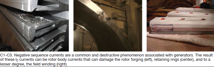
A common and destructive phenomenon in generators is negative sequence currents (I2), MD&A Project Engineer Chris Keathley told GUG 2017 attendees. These can be caused by unbalanced three-phase currents, unbalanced loads, unbalanced system faults, open phases, and asynchronous operation. The result of I2 currents may be rotor body currents that can damage the rotor forging (Fig C1), retaining rings (Fig C2), slot wedges (Fig C3), and to a lesser degree, the field winding.
Three case studies were reviewed by the speaker, who brought to MD&A 16 years of experience with a major utility as a turbine/generator engineer, and another five years with the OEM.
Case Study No. 1. A 500-MVA, 22-kV, 3600-rpm generator had been involved in a motoring event of unknown size and duration five years before the inspection described was conducted. A visual assessment revealed relatively minor problems—such as slight burning between wedges, significant burning on wedge ends, and burning of the forging at wedge junctions. Eddy-current testing revealed 290 indications. Affected areas were cleaned and blended. A TIL 1292 (“Generator Rotor Dovetail Inspection”) repair on the Coil No. 1 Slot was done and steel wedges were replaced with aluminum (except end wedges). A high-speed balance and heat run were conducted after rewind.
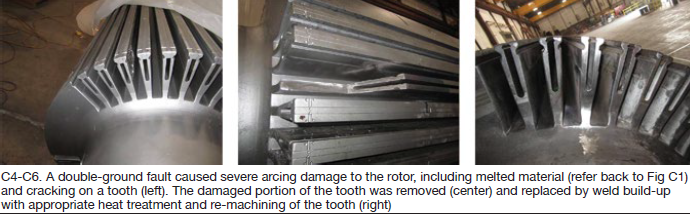
Case Study No. 2. A two-pole field suffered a double ground fault that caused severe arcing damage to the rotor, including melted material and cracking on a tooth (Figs C1 and C4). NDE of the area revealed a through-wall crack and an engineering evaluation determined the rotor unacceptable for operation. A temporary weld-repair solution was proposed to get the unit back in service until a replacement rotor could be obtained. The damaged portion of the tooth was removed (Fig C5) and the tooth reconfigured with weld build-up, rotor heat treatment, and re-machining of the tooth (Fig C6).
Finite-element models of the rotor and slot tooth were created to obtain the various stresses along the tooth height, the weld fusion line/HAZ, and the highly stressed wedge groove fillet radius. These stresses and mechanical properties were used in fracture-mechanics calculations; favorable results supported acceptance of the repair. A fatigue analysis of the repaired tooth suggested the reworked rotor was good for 150 start/stop cycles or 10 years of operation, whichever came first.
Case Study No. 3. A generator experienced a collector failure and ground to the main shaft that caused major arcing and heat damage to the end of the generator rotor forging (Fig C7). The amount of damage and heat-affected material made the shaft end forging unacceptable for continued operation. Stub-shaft replacement was proposed and accepted by the owner.
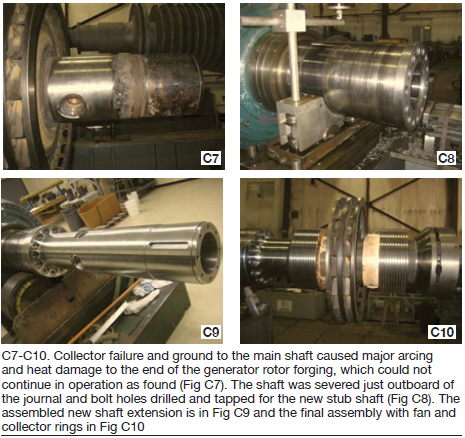
This was a major undertaking. The shaft was severed just outboard of the journal and bolt holes drilled and tapped for the new stub shaft (Fig C8). The assembled new shaft extension is shown in Fig C9, and the final assembly with the fan and collector rings in Fig C10.
To conclude, negative sequence events and ground faults are preventable by good operation and monitoring equipment. When those defenses fail, considerable damage can occur. However, it does not always mean that the damage cannot be repaired and the unit returned to service. These case studies show that even when there is damage, advanced welding and machining processes can restore the unit to service relatively quickly.
Collector rings: Inspection and repair
MD&A’s Keith Campbell, an industry veteran with four decades of experience, showed and discussed numerous photographs to illustrate the inspection, failure modes, and repair of collector rings.
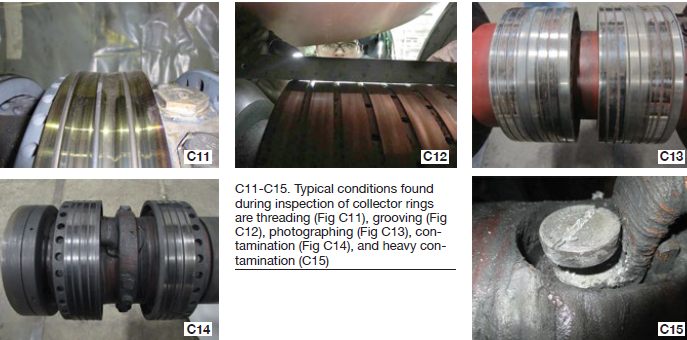
Inspection. Typical conditions found during inspection are shown in photos C11-C15. Threading and grooving (Figs C11 and C12) naturally result from the wear and tear of long service. Photography (Fig C13) is not common nor well understood; it describes the phenomenon in which the pattern of the brush holders is replicated on the rings. There is inevitable contamination associated with the collector (Fig C14) from sources that include brush wear, induction of foreign material with the cooling-air flow, and uncorrected arcing. Massive contamination is caused by flashover failure (Fig C15).
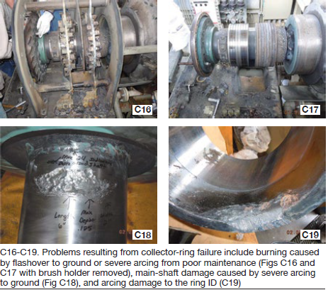
Failure. Typical problems resulting from failure are seen in the photos C16-C19. In the first, the right ring was severely burned by a flashover to ground or severe arcing from poor maintenance. The adjacent image shows a similar condition but with the brush holder removed. Fig C18 is of damage to the main shaft from severe arcing to ground, C19 shows corresponding arc damage to the ring inside diameter.
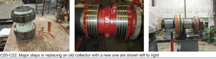
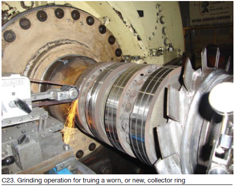
Repairs. Figs C20-C22 illustrate steps in replacing an old collector with a new collector, Fig C23 is of a grinding operation for truing a worn, or new, ring.
An unusual generator field ground
The incident profiled here by John Demcko, PE, a senior consulting engineer at Arizona Public Service Co and member of the GUG steering committee, occurred at an APS plant equipped with three single-shaft combined cycles installed in the mid-1970s.
The generators serving these units are rated 146.7 MVA/13.8 kV; they were retrofitted with static excitation systems and redundant digital regulators several years ago. This update included a modern 64F field ground detection system, which experienced a continuous field ground alarm over a year ago. The incident was treated routinely—that is, management was informed.
Management was made aware of the risks associated in running with a known ground. The decision was made to remain online until an outage could be scheduled to evaluate the situation. When that happened, a Megger test of all components in the field winding circuits showed no ground.
The 64F relay is only operative when there is excitation on the machine since it is powered from the excitation power potential transformer. With the unit offline and not spinning the 64F was powered up with a “cheater” cord. No field ground was detected by the relay in this configuration. The 64F relay was switched out for an identical spare which also indicated no ground with the unit offline but did indicate one with it spinning and the field energized.
This implied that the ground was on the rotor and was caused by the centrifugal loading of the field winding. The unit was put back in service and was run almost daily with the apparent field ground while a new 64F relay was ordered from another manufacturer. The new 64F was installed and behaved exactly as the previous two relays.
A last-ditch effort was made to spin the unit up to synchronous speed with excitation off. Meggering of the field via the carbon brushes and slip rings found the resistance to be in the megaohms range. There appeared to be an impasse when a ground was indicated in the field circuit but could not be localized.
After re-verifying the accuracy of all data taken, an investigation was conducted to look for any other elements that can fault to ground when the exciter is running. Several manufacturers of field ground detection equipment were asked if their equipment could detect faults on the AC side of the static excitation system. Responses were mixed, but one vendor said AC-side grounds can definitely be detected, although their occurrence is highly unusual.
Additional voltage-to-ground measurements were made on the AC side of the static excitation system breaker for all three units. A fundamental difference in readings was noted on Unit 2 as compared to Units 1 and 3 which did not have field grounds. This inferred an AC side excitation system ground was causing the 64F relay to indicate a field ground. A precise physical model of the static excitation system, including the same 64F, was constructed. It confirmed that an AC ground is easily detected by the 64F and the lab measurements very closely matched the data taken of the actual machine.
The unit will be operated until a scheduled outage allows for AC fault confirmation and repairs.
Brush-holder experience
John DiSanto’s presentation focused on collector incidents and avoidance. The GE senior engineer, who is responsible for generator controls/excitation and protection fleet-wide with the goal of improving equipment reliability, reviewed nine recent root-cause-analysis investigations.
They involved collector flashovers, collector-ring overheating, improper collector-ring assembly, and a damaged insulating sleeve.
Two of the case studies illustrated unnecessary forced outages. One involved overheating of the inner collector-ring surfaces, molten brush holders, and arcing of collector housing. The second case revealed a heavily worn brush and brush-holder damage. The collector surface was found to have salt deposits and corrosion.
Daily, weekly, monthly, and outage inspection and maintenance were reviewed. DiSanto also offered a few comments on maintenance—for example, the importance of cleaning, collector-ring wear rates (1 mil per 1000 hours of operation is typical); permissible wear (the ring diameter can be reduced but must always be larger than the diameter of the bottom of the spiral groove); maintaining proper cooling on collector rings (design temperature is 40C); and recommended brush grade (National 634).
The presentation closed with a discussion of brush-rigging upgrades. GE was said to have a well-defined set of brush-holder design criteria, including the following:
-
- Allow for safe installation and removal of brush holders with the generator online.
- Improve ease of brush and spring replacement—no tools required.
- Eliminate brush “hang-ups” within the holder by having a fully supported brush and a smooth/slick brush pocket.
- Decrease the risk of flashover.
- Decrease susceptibility to brush current selectivity—that is, uneven current distribution among brushes.
- Allow easy integration for both servicing and replacement across all GE generator models.
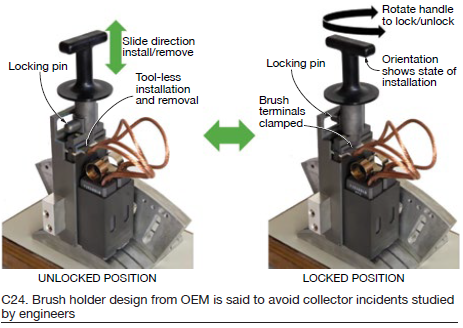
The company’s most recent brush-holder design for generators of moderate size (Fig C24) was said to meet these criteria.
Digital excitation replacing ageing technologies
If you were relatively new to the industry, listening to the presentation by Basler Electric Co’s Richard Schaefer at GUG 2017 provided valuable perspective on excitation systems. A former chair of the IEEE PES Working Group, he’s “seen it all” in more than four decades of service to power producers. His CliffsNotes on the evolution of excitation systems: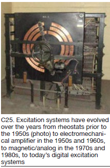
-
- Before the 1950s, rheostats (Fig C25).
- 1950s and ‘60s, amplidyne.
- 1970s and ‘80s, magnetic/analog.
- Late 1980s through today, digital.
Several factors affect how quickly systems become obsolete, he said—including, available materials, present technology, and available software. Examples of materials availability issues: carbon composition can no longer be manufactured, warlords have taken over the mines, material determined to be hazardous. Examples of hardware availability issues: primitive computers, present-day powerful computers.
Schaefer note actions that have contributed to the slowing of obsolescence—for example, purchase of components from manufactures serving major long-survival industries (such as automotive), redesign of product with new components where practical, purchase large volumes of obsolete components.
Particularly in recent years, there has been upward evolution in software. For example multilingual capability, built-in powerful testing tools, enhancements to speed commissioning. Also there are options to facilitate retrofit—for example, replacement product fits into same location, provide replacement excitation cabinets but keep the power potential transformers, keep SCR bridges and provide new front-end electronics.
Shaft earthing monitoring
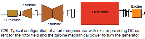
Andre Tetreault, director of tests and diagnostics at VibroSystM, and co-author Bernard Lemay, PEng, the company’s Zoom analytical software expert, opened their presentation by reminding the GUG 2017 audience that, in the ideal, the generator shaft should be electrically and magnetically neutral during operation. The use of ferromagnetic materials in the construction of the shaft makes this component extremely conductive and subject to current flow and induced voltages. A typical turbine/generator configuration is shown in Fig C26; the exciter provides DC current for the field, the turbine provides mechanical power.
At least one generator bearing is insulated from ground. On other bearings, a thin oil film is the only barrier separating the shaft from the ground and this film may not act as insulation to current flow.
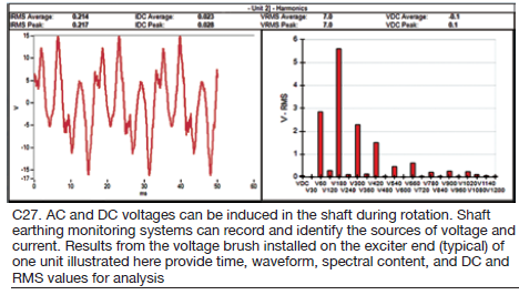
Both AC and DC voltages can be induced in the shaft, causing potential damage to the unit— especially the bearings. Shaft earthing monitoring systems can record and identify the various sources of voltage and current, allowing for analysis and damage prevention. One brush is installed to monitor voltage (diagnostics), usually on the generator exciter end, and one to monitor current (protection), usually on the turbine end.
Results from the voltage brush are shown in Fig C27. Time, waveform, spectral content, in addition to DC and RMS values, are available for analysis. Alarm levels are set after results are analyzed.
Protection schemes using trends of shaft currents are common, but do not provide diagnostics. In many cases, alarms triggered will confirm existing damage, instead of detecting ongoing issues and/or preventing future damage. Voltage frequency profiles should not evolve over time.
High-speed data acquisition, and comprehensive diagnostics software, allow for in-depth analysis of harmonics to identify various anomalies. Patterns such as high even harmonics may indicate rotor alignment or stator bar problems. If deviations are present, other symptoms may include stator vibration and/or bearing temperature variations.
High DC levels should trigger a ground connection investigation and if the shaft is magnetized, bearing temperatures should be verified.
Operation and monitoring
-
- Mini turbine/generator model for training. John Demcko, PE, Arizona Public Service Co
- Generator abnormal operation. Ron Halpern, Generator Consulting Services
- Effects of negative-sequence and off-frequency currents. Izzy Kerszenbaum, IzzyTech
- Impact of cycling duty. Jamie Clark, AGT Services Inc
- Generator cyclic duty. Ed Winegard, GE
Mini turbine/generator model for training
John Demcko, PE, a senior consulting engineer at Arizona Public Service Co and member of the GUG steering committee, spoke to the industry’s knowledge gap and work his company was doing to bridge that gap. Many new powerplant engineers and technicians, he said, have no formal training on how to bring generating units online and take them offline. Nor are they usually familiar with how generators interact with the grid.
The 40-plus-year industry veteran added that plant engineers and technicians are good at addressing mechanical issues but typically are not well versed in the electrical characteristics of synchronous machines. A PowerPoint-only class had been offered for many years at APS but personnel were not being prepared adequately for the challenges they faced daily.
Demcko’s department of four engineers functions as a “consulting firm” internal to the utility. Over the years, electrical training responsibilities defaulted to his group because it was intimately involved with problems on the generator, exciter, automatic voltage regulator, and power-system stabilizer. Since operating staff tend to be “visual learners,” he continued, a physical model-based training approach was proposed to management. It was accepted and a wish list of model functionality was developed. The search began for a commercially available training model.
The “wish list” of features desired for the model included the following:
-
- Three-phase synchronous generator.
- Power level compatible with a nominal 5-amp CT output and 120-Vac PT output found in utility generation.
- Utility-style control switches and metering.
- Digital generation protection relay.
- Auto-synchronizer and emulation of generator breaker function.
- Drive motor with the ability to mimic turbine characteristics.
- Synch to grid at either 208 or 480 Vac.
- Have the look and feel of a typical physical generator control panel.
- Portability (movability).
Search results. North American universities were canvased and educational suppliers queried. Nothing commercially available met all of APS’s requirements at any price. Conclusion: The utility would have to build a custom model.
Custom build. Team Demcko received approval to build its own model with a modest hardware budget. Engineering and labor was to be done by staff on a time-available basis—such as between regular assignments. Cost of the model would be contained by purchasing/scrounging as many components as possible off-the-shelf. A target of one year was established for completion of the model.
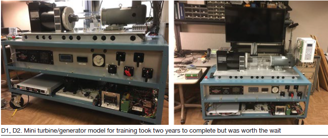
Results/observations. The model, highly modular in construction, took two years to complete because of limited availability of labor (Figs D1 and D2). It was good for troubleshooting but had many terminal blocks for interconnection that could loosen. Classes started in April 2017; 102 APS employees were trained. The first four weeks of onsite plant training was completed near the end of August with 84 attendees. Remainder of the fossil fleet (several hundred “students”) was scheduled for onsite training before yearend. Results: Almost all the design targets were achieved, but some refinements to the model were suggested.
One use of the model that Team Demcko did not fully anticipate was for training plant operators in manually closing the generator breaker to synch the unit. While an auto-synchronizer normally is relied on for this task, APS expects its control operators to have the ability to do it manually. Trainees appreciated being able to practice synchronizing the generator with the electric system using the model, without risking damage to critical equipment.
Generator abnormal operation
Ron Halpern of Generator Consulting Services opened his presentation by defining “abnormal operation” as any operation outside normal operating parameters that could damage the generator—such as operation outside of the generator capability curve.
The speaker, who has been involved with generators for well over 40 years, 25 of those at GE, focused his presentation on the following:
-
- Stator—including core, oil, hydrogen leaks, grounds, stator cooling, water leaks and restrictions, bushings, and frame.
- Rotor—including grounds, shorted turns, thermal sensitivity, shaft voltage, and collectors.
- Auxiliaries—including loss of hydrogen seals, coolers out of service, and on moisture corrosion and contamination.
- Electrical and grid—including over fluxing, off-frequency operation, loss of synchronization, motoring.
Typical abnormal-operation events discussed included the following:
-
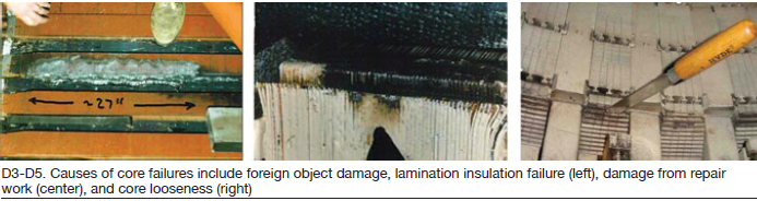
- Core failures. They may be caused by foreign object damage, lamination insulation failure (Fig D3), damage from repair work (Fig D4), loose core (Fig D5), etc.
-
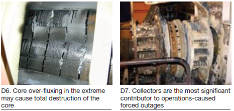
- Core over-flux, a complex phenomenon. Protection is via volts-per-hertz relay. Minor over-fluxing (105%-110%) increases core losses and elevates core temperature but should cause no damage. Over-fluxing above 110% saturates portions of the core to the point that flux flows out into adjacent structures and, if sufficient and sustained, may cause total core destruction (Fig D6).
-
- Rotor ground. The excitation system is ungrounded and a single ground will not cause damage (unless the cause is a broken conductor or coil short). However, a second ground can be disastrous. There are many possible causes—including ground-wall insulation breakdown, contamination, electrical arcing, displaced insulation, and water intrusion into the exciter. Collectors are the most significant contributor to operations-caused forced outages on generators; the results can be dramatic and dangerous (Fig D7).
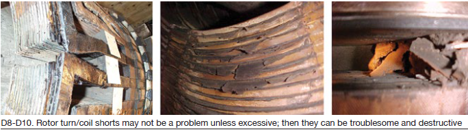
- Rotor turn/coil shorts. Shorts may not be a problem unless excessive and you run out of current, or if they result in high thermal-sensitivity vibration. But they can be destructive (Figs D8-D10).
-
- Thermal sensitivity can be problematic. It causes rotor vibration to change as the field current is increased and can cause rotor bowing when (1) the temperature distribution is uneven circumferentially around the rotor and/or (2) axial forces are not distributed uniformly in the circumferential direction. The phenomenon, characterized by a once-per-revolution frequency response, may limit operation at high field currents or VAR loads because of excessive rotor vibration.
- Shorted-turn detection. The most reliable method for detecting shorts is by use of a flux probe. The technology is well understood and reliable.
Other items briefly discussed included oil in the generator, stator-bar slot support systems, high- voltage bushing, seal leaks, noise causes and investigations, and damage prevention in general.
Effects of negative-sequence and off-frequency currents
From early on, AC synchronous generators were designed to produce three-phase balanced voltages at their terminals, began Dr Izzy Kerszenbaum, PE, of IzzyTech. Over time, the design also incorporated features to reduce the harmonic content of the generated voltage. In the case of generators, the problem was (and still is) mainly related to unbalance in the load currents, while in the case of AC motors, the problem was (and still is) related to unbalanced supply voltage.
The negative-sequence current component circulating in the stator windings creates a magnetic flux in the airgap of the machine, continued Kerszenbaum, a well-respected teacher of things electrical and prolific author with more than 40 years of service to the industry. This flux rotates at synchronous speed, but in the direction opposite to the positive flux (the “normal” flux), he explained.
The rotor, also rotating in synchronous speed in tandem with the positive magnetic flux, is subject to a 2× synchronous frequency magnetic flux, by the negative flux. Then, by the law of electromagnetic induction (Faraday), 2× synchronous frequency voltages and eddy currents are induced in the rotor body. Given that these induced currents have a periodicity of 120 Hz in 60-Hz systems or 100 Hz in 50-Hz systems, they tend to flow mainly in the outer regions of the rotor, because of the “skin effect.”
Net result: If large enough, the induced currents will spark and arc between wedges, wedges and forging, wedges and retaining rings, forging and retaining rings, and any component on the periphery of the rotor. Such sparking/arcing can cause hardening of the metal in critical areas, followed by the generation of cracks.
From the foregoing, it is obvious that negative-sequence current carries with it the potential to cause significant damage to the generator; thus, protection against these currents must be provided. In the event a large negative-sequence event occurs, (as with a major short-circuit between phases in the vicinity of the machine), it behooves the operators to carry out an assessment of the possible damage incurred by the machine, followed by a proper inspection, if warranted.
Impacts of cycling duty
Generators built during the gas-turbine order/installation “bubble” in the late 1990s and early 2000s, look very much like their predecessors built in the 1950s, 1960s, and 1970s. However, unlike their predecessors, the newer machines are not giving the 20 to 30, or more, years of reliable service expected.
OEMs have designed similarly sized machines for MVA ratings 40% to 50% higher than their predecessors, while pushing material capabilities to their maximum. Plus, demands on equipment have been exacerbated by the need to cycle these generators hundreds of times annually to accommodate must-take renewables.
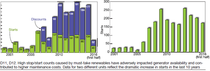
 Generators were designed to run at base load or, worst case, for minimal annual start/stop counts—perhaps 50 to 75. However, as the charts in Figs D11 and D12 for two case histories show, they are seeing 250+ starts per year. Units in renewables-heavy markets are exceeding 350-400 annual starts. This takes low-cycle stresses from thermal expansion/contraction, and moves it into a high-cycle realm. The end result is that units are either suffering in-service failure or, at a minimum, are requiring very costly repairs or maintenance/upgrades at their first major outages, within 10 to 15 years.
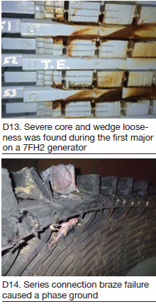
In his presentation, AGT Services Inc’s Jamie Clark pointed to common weaknesses exacerbated by these high cycling operations—including loose stator wedge systems (Fig D13), axially loose core iron, loose endwindings, global endwinding dusting or broken ties, loose belly bands, bar movement in the stator slots, high partial discharge and resulting corona damage, and increased opportunities for seal-oil problems resulting in oil entering the unit, which further accelerates the previous issues.
In the field, the impact is found in cracked or failed main leads, pole/pole and coil/coil crossover jumpers, migration of slot armor, deformation of field endwindings, loose/missing/broken distance blocking, migrating coils, insulation, or amortisseur springs resulting in blocked cooling, thermally sensitive fields, rapid turn short development, and myriad other issues (Fig D14).
Generator cyclic duty
In recent years there has been a changing of the generator lifecycle. These machines originally were intended for baseload operation and 30 years of service. There has been an industry shift to frequent starting/stopping, load cycling (described as more than two 20% changes in megawatt output in a 24-hr period with two primary load cycles (50% – 100%) in a typical day), VAR cycling, and seasonal influences.
Frequent starting/stopping imposes additional stress, with faster degradation of insulation and components, negative impact on generator life, higher risk of in-service operating incidents—all likely contributing to increased maintenance.
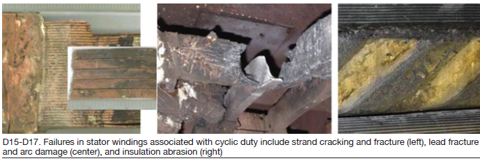
Cyclic duty involves start/stop operation, load cycles, and power-factor changes. Impact on stators includes vibration transients, thermal and mechanical stresses, and core-end heating. Some of the effects on stator windings and core are high- and low-cycle fatigue, insulation abrasion, strain, shorts or grounds, localized overheating, and core-iron melting. Typical failures are strand cracking and fracture (Fig D15), lead fracture and extensive arc damage (Fig D16), and insulation abrasion (Fig D17).
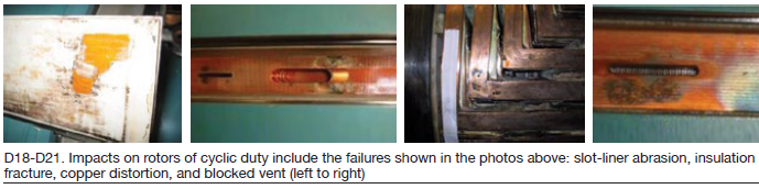
Cyclic-duty impact on rotors includes copper distortion, insulation breakdown, shorted turns, connector failures, grounds and forging damage. Typical resulting failures are shown in Figs D18-D21: slot liner abrasion, insulation fracture, copper distortion, and blocked vent (left to right).
Twenty-five-year GE veteran Ed Winegard, currently principal engineer for armatures, described for attendees several design features developed to accommodate cyclic operation. You can access a copy of Winegard’s PowerPoint on the Power Users website.
Maintenance and inspection suggestions for cyclic duty, also covered in the presentation, include the following:
-
- Maintain equipment in accordance with GEK 103566.
- Conduct additional testing during scheduled outages.
- Perform regular borescope and robotic inspections.
- Do modal testing of endwindings.
- Provide for additional monitoring during operation.