There are numerous instrumentation systems used in attempts to assess the condition of powerplant electrical equipment. The library of papers about them is vast. But papers discussing detection of failing electrical connections inside generators or bus systems are limited in number, Consultants Clyde V Maughan and James E Timperley told the editors.
 The focus of the editors’ discussion with these respected experts, who have a combined electrical experience base of more than a century and a half, was on instrumentation that will readily detect joints in the early stages of distress, with the objective of preventing expensive in-service failures.
Bolted-joint deterioration. There are thousands of high-current (non-instrumentation) electrical connections in a powerplant. All are subject to deterioration, bolted joints in particular. They may eventually fail, the consultants stressed, if not well designed and properly assembled.
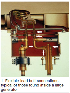
Fig 1 shows the locations of several bolted connections internal to a large generator. Failure of these connections is rare but can be extremely costly when they do occur.
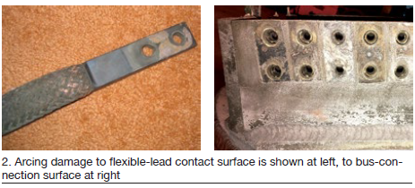
Deterioration from imperfect high-voltage-bushing flexible connection joints is shown in Fig 2. This condition is the result of high contact resistance attributed to less-than-specified torque on the connection bolts and/or improper cleaning of the joint faces. Repair would involve cleaning and re-plating of the connection surfaces on the plates and on the flexible links. Or replacement of links if significantly deteriorated.
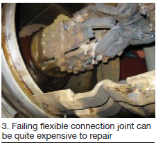 A serious joint failure is illustrated in Fig 3. Restoration of this condition would involve local cleaning, replacement of lost metal, and reconditioning of the plated surfaces. Costs in outage time and repair would be significant.
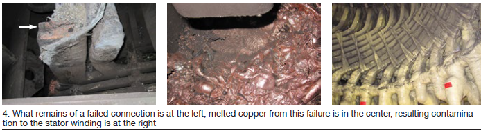
At the extreme high end of the damage spectrum is the failure of the 900-MW generator in Fig 4. Repair involved installation of a new stator winding, a rotating-field rewind to facilitate cleaning of the winding, and extensive and difficult cleaning of the core and frame. The failure was catastrophic in that it involved a six-month forced outage costing more than $100 million in repairs and replacement power, according to Maughan, who has first-hand knowledge of this accident.
All of these conditions would have been radiating high electromagnetic-interference (EMI) energy for some period before failure occurrence. This could have been detected and the failure prevented, Timperley said.
Assessing equipment condition can be difficult. The most powerful tool is visual inspection by a well-qualified individual. But this usually requires equipment shutdown and at least some disassembly. Thus, high emphasis always has been on testing, with online testing preferred.
For example, on a generator stator winding there are many such tests:
-
- Several types of over-voltage test.
- Various partial-discharge (PD) systems.
- Flux assessment.
- Winding modal analysis.
- Wedge tightness.
- Numerous special tests of winding direct-cooling systems.
- Electromagnetic interference testing.
EMI testing may be done by either of the methods described below:
1. Electromagnetic signature analysis (EMSA) is applicable to powerplant equipment such as generators, motors, and transformers. Generally, it is not useful for locating joint deterioration. The EMI signal is obtained from a radio-frequency current transformer commonly placed on the grounding cable of the equipment in question.
This full-spectrum analysis, while valuable, does not have the ability to detect where a defect is located. Also, it can be very difficult to interpret the signal with accuracy relative to severity and isolation. As a result, the use of EMSA is limited.
2. A hand-held so-called “sniffer,” which is discussed in the remainder of this article.
It was said that measurement of radiated EMI using the hand-held sniffer has powerful condition-assessment capability for electric equipment. However, it also has not been a widely used technology relative to powerplant equipment. A common reservation regarding the sniffer revolves around the belief that a generator frame or bus enclosure acts as a Faraday Cage and does not allow EMI to escape.
Recall that a Faraday Cage is constructed of conductive materials with only a few well-shielded openings. Commercial EMI-free rooms are often two layers thick with the layers insulated from each other and with both layers grounded at a single location. Special conductive gaskets and grounding methods are used at the doors and other openings.
The steel enclosures of powerplant generators, motors, bus, and switchgear are very imperfect Faraday Cages. The strong EMI signals emitted by failing joints are able to pass through those enclosures.
The discussion that followed focused on the use of the measurement of radiated EMI for detecting deteriorating electrical-current connections for these reasons:
-
- Many types of highly important deterioration can be detected by in-service EMI testing.
- EMI testing is completely non-intrusive.
- There is no danger to personnel or equipment.
- Relatively little effort is involved; an entire turbine/generator and its associated electrical equipment can be assessed comfortably in an hour.
- The saving from avoiding a single forced outage on a single piece of equipment can be huge.
History. Detection of EMI radiation in powerplants for evaluating the condition of powerline insulators dates back many decades. More recently, its use in finding failing connections has proved very effective. The technology is basic and easy to understand: Any poor electrical connection produces arcing which, in turn, produces electromagnetic radiation. The strength of the radiation field depends on the magnitude of the arc, distance from the arc source, and any shielding of the arc that exists.
Since arcing is a common deterioration mechanism where electric current is flowing, this type of monitoring is a powerful tool for assessing the condition of powerplant equipment.
Maughan and Timperley introduced the editors to a small, hand-held instrument on the market that can readily measure the strength of this radiation, the Partial Discharge and EMI Locator (Model 246A, Fig 5) from Radar Engineers, Portland, Ore. There may be other instruments available with the capabilities of this device, but the authors are not aware of any.
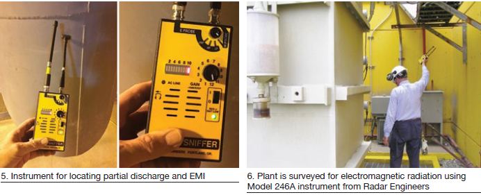
This device weighs less than a pound. It is versatile and has a wide range of sensitivities—low using the magnetic H-field antenna, high using the LF/HF/UHF electric E-field antenna. The instrument comes with written instructions for use in a powerplant and can be used without formal onsite training.
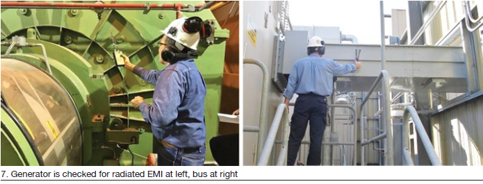
The Model 246A has been in use since about 2000. Widespread application has been limited primarily because its availability and capability were not promoted. With this instrument, sources of EMI are identified simply by scanning equipment on a plant walk-around and observing the output of the device (Fig 6). A typical generator or bus can be scanned in a few minutes (Fig 7).
 Experience suggests that roughly 90% of typical equipment failure modes emit detectable radiation EM energy, thus accounting for the high potential value of the test.
By observing the location and magnitude of detected signals it is possible to make valid judgments relative to the nature of suspected deterioration. Based on this information, necessary inspection and additional tests can be planned to reduce the likelihood of further damage and/or forced outage on specific equipment.
If signals of concern are identified, trending of signal magnitude over time can be helpful in assessing equipment condition.
Despite its limited use, the Model 246A and its predecessors have found many dozens of actual defects ranging from minor to serious (sidebar). A particularly instructive and important case involved the large generator that suffered the damage in Fig 4. After this generator was repaired, it was decided to use the Model 246A instrument to survey the repaired generator and an identical sister unit.
While the survey of the repaired unit did not detect any winding or connection problems, the survey of the sister machine identified minor EMI activity in the connection area (the location of the first unit’s failure). It was decided to monitor this area until the next scheduled outage one year later. A scan a few months before the scheduled outage showed continued minor sparking related to the endwinding or phase leads. Note: There was no difficulty obtaining the EMI signals through the imperfect Faraday Cage of the generator terminal box.
Defects found in bus and switchgear
A variety of conditions have been detected inside bus and switchgear by the Radar Model 246A—including the following:
- Loose bolts on center conductor.
- Loose bolts on enclosure.
- Loose disconnect-switch parts.
- Broken high-current shunts.
- Defective PT connections.
- Open fuse links.
- Defective breaker contacts.
- Contaminated insulators.
- Cracked and loose insulators.
- Shorted enclosure insulation.
- Foreign objects inside enclosures.
- Loose connections to surge pack.
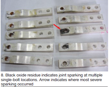
When the generator was removed from service, engineers found the bolted flexible joints from connection ring to neutral had started to loosen and were sparking. Flexible connectors for one joint are shown in Fig 8. The engineers believed this generator was well on its way to a catastrophic failure like the one suffered by its sister unit.
Wrap-up. Radiated radio-frequency EMI energy from defective electrical joints can be detected and the source localized with the use of a readily available instrument. Corrective actions then can be taken well before a failure occurs. The dollars returned for scans of radiated EMI are orders of magnitude more than the cost of the tests.