Insights into the value of a proactive approach to planning a full stator rewind to prevent costly failures and extend the operational life of the 7FH2 generator
By Joe Hopfinger, ENTRUST Solutions Group
The GE 7FH2 generator remains one of the most widely deployed machines in gas-fired power generation. Introduced in the mid-1990s, nearly 1,000 units have been placed in service globally, providing a significant share of total installed gas-turbine–driven capacity. The model’s long operational history and extensive user base make it a benchmark reference across the industry for large hydrogen-cooled, 60-Hz generator design and reliability.
Today, many utilities operate multiple 7FH2 generators across fleets that include both legacy F-class and newer configurations. As these units approach the three-decade mark, understanding their construction, known fleet issues, and long-term maintenance strategies, particularly stator rewinds, is essential to ensure continued reliable operation.
This article reviews the major design features of the 7FH2 generator stator, outlines common failure mechanisms observed in the fleet, and explains how a properly executed stator rewind can reset the life of this critical component. It also explores the operational and economic implications of deferring such work and offers planning considerations for utilities managing 7FH2 fleets entering mid-life renewal.
Key stator components
The stator frame of the 7FH2 generator incorporates an integral base that mounts directly to a slab foundation. The gas-tight cylindrical casing, fabricated from welded steel plates, provides both mechanical rigidity and containment for the hydrogen-cooled system. This configuration reduces vibration transmission and contributes to long-term structural stability.
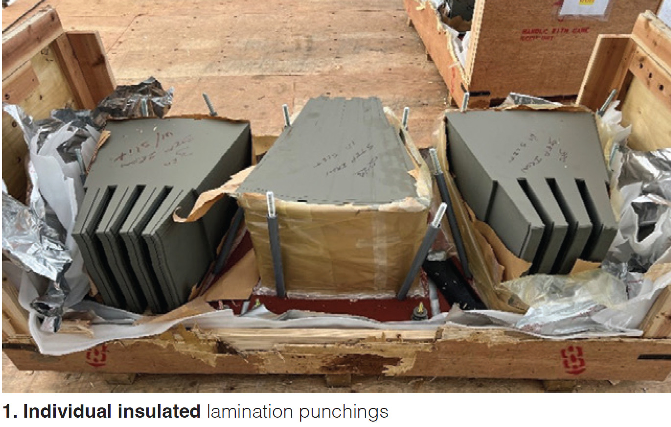
The stator core consists of thin, insulated metal laminations, approximately 0.014 inch thick, stacked circumferentially in an interleaved pattern. Each lamination is coated with an insulating varnish to prevent eddy-current formation and interlaminar electrical contact (Fig 1). The core is typically assembled vertically, beginning at the connection end (CE) and building toward the turbine end (TE), where it is axially compressed via key bars to achieve uniform tightness across the stack (Fig 2). Ventilation ducts are distributed between the core sections to channel hydrogen coolant through the core and around the winding, ensuring efficient heat dissipation during operation.
Within the core, stator slots accommodate the copper armature bars. Each lamination includes open slots for the bars and dovetailed grooves for the wedges that secure them. The stator winding is composed of insulated copper bars transposed using the Roebel method, which ensures each strand alternates through every radial position along the bar. This design equalizes magnetic flux exposure, minimizing circulating current losses under load and promoting thermal balance along the length of the coil.
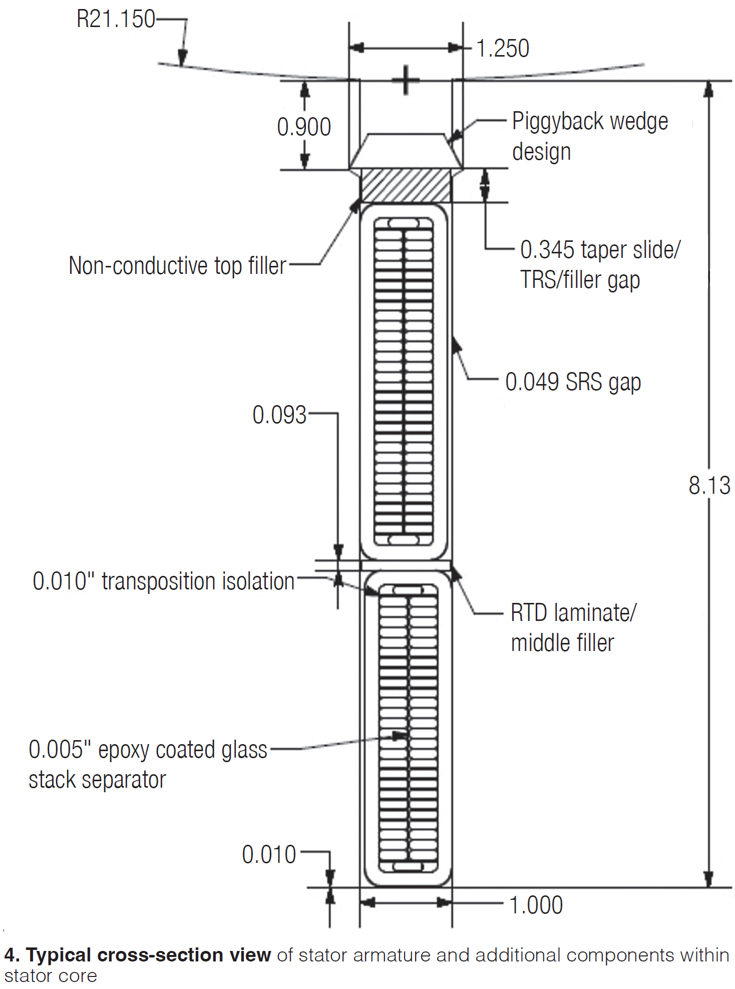
Each stator bar receives a multilayer insulation system forming the “ground wall (Fig 3).” This system typically uses mica tape bonded with a thermosetting epoxy or resin binder. During manufacturing, the bars are placed in a vacuum-pressure impregnation (VPI) tank, where pressure and heat cycles remove volatiles, compact the insulation system, and cure the binder. The result is a dense, void-free dielectric barrier with excellent mechanical strength and thermal endurance (Fig 4). The insulation is rated to maintain dielectric integrity across the full expected temperature range for hydrogen-cooled service.
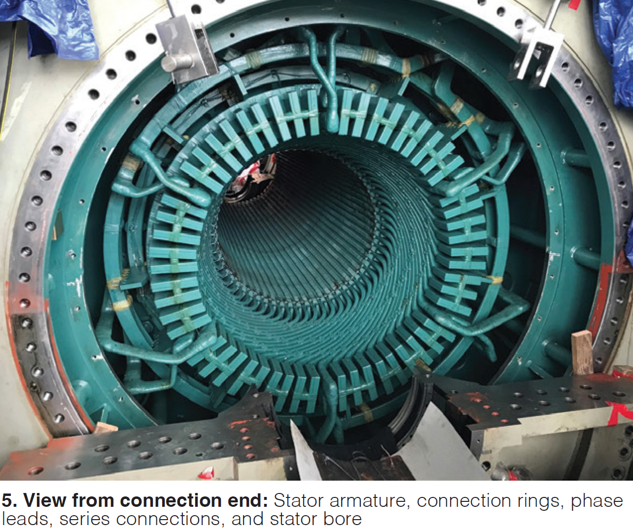
To reduce abrasion within the stator slot, the bars are wrapped in armoring tape, while voltage-grading coatings extend several inches beyond the core to reduce corona discharge. At the end-turn region, the coils are bound by molded fiberglass rings, supported by the stator core flanges and secured with thermosetting resin. Conformable materials are added to evenly distribute mechanical stress, and all components are bonded into a solid structure designed to withstand thermal expansion and electromagnetic forces during operation. Finally, the armature bars are locked into position by wedges driven into the dovetail slots, completing a tightly secured winding assembly (Fig 5).
Planning for a stator rewind
The expected design life of the 7FH2 stator is approximately 30 to 40 years, at which point a comprehensive stator rewind is generally recommended. A rewind involves complete replacement of the stator windings and insulation system and, in many cases, inspection and rework of the core and frame. Once complete, this process effectively resets the generator’s operating life to “as-new” condition.
A full rewind typically requires three and a half to four weeks to complete once all materials are on hand, though total outage duration can extend if the field requires additional disassembly or repair. Because rewinds depend on the timely availability of key materials, including copper bars, core laminations, and fiberglass components, advance planning is critical. These components often carry manufacturing lead times ranging from several weeks to several months.
With the earliest 7FH2 units from the mid- to late-1990s now approaching 30 years in service, many owners are beginning to plan for these lifecycle overhauls. Proactive scheduling aligns with OEM guidance and ensures adequate time to secure both materials and qualified labor resources. For multi-unit sites, staggered planning also minimizes simultaneous downtime and helps avoid congestion in vendor or OEM production queues.
Failure to plan rewinds in advance can expose utilities to higher risk of forced outages, especially if a stator fault arises unexpectedly. Because the stator is a non-redundant component, meaning there is no backup for its function, a major failure can take a unit out of service for an extended period, directly affecting plant capacity and market participation.
Common failure modes
Over nearly three decades of operation, several recurring technical issues have been identified across the 7FH2 fleet. While not universal, these patterns are well documented among both OEM and user-maintenance communities.
Typical failure modes include:
- Stator armature issues. Vibration-related mechanical wear, thermal distress, fatigue spark erosion, ground faults, loose wedges, insulation dusting or greasing
- Stator core issues. Shorted laminations causing local hot spots, back-of-core burning, iron fretting, and in rare cases, melting
- General assembly issues. Dry-tie dusting, loose end-winding axial support hardware, core-iron manufacturing inconsistencies, and generator terminal-enclosure weatherization problems leading to moisture ingress
Each of these conditions can degrade reliability or lead to progressive deterioration if not addressed. Many users have adopted enhanced inspection protocols, including wedge-tap testing, partial discharge analysis, and end-winding vibration monitoring, to detect early indicators of insulation or mechanical distress.
Operational profile also strongly influences component aging. Baseload units tend to exhibit thermal aging of insulation systems, whereas cycling or peaking units face more pronounced mechanical fatigue from frequent start-stop transients. Other life-limiting factors include the total number of operating hours, number of starts, load ramp rates, and environmental conditions at the installation site. Understanding how these factors apply to a given machine allows utilities to prioritize maintenance and weigh the timing of a rewind within their broader asset-management plans.
Risks of deferred maintenance
The consequences of deferring a stator rewind can be significant. Lead times for custom copper bar sets or core iron replacements are typically measured in months, not weeks. Manufacturing slots are limited, and availability can tighten further during peak outage seasons. In the event of an unexpected fault, such as a winding ground failure or inter-turn short, operators may face extended downtime while waiting for replacement materials.
This delay can translate directly into lost-generation revenue and potential contractual penalties for plants operating in capacity or reliability markets. Furthermore, emergency rewinds conducted under schedule pressure often come at a higher cost due to expedited shipping and overtime labor.
Routine condition assessments and trending of key indicators such as partial discharge, vibration, and insulation resistance are therefore essential. If results show progressive deterioration, utilities should move from reactive inspection toward proactive corrective planning. Implementing a rewind before the onset of critical failure ensures controlled execution, predictable outage duration, and reduced exposure to secondary damage.
Resetting generator life cycle
Executing a full stator rewind within the 30- to 40-year window effectively resets the generator stator to a new-life condition. By replacing the winding, insulation, and end-winding support system, the most age-sensitive components are renewed. The process also allows for inspection and, if necessary, refurbishment of the stator core, frame, and ventilation systems.
Utilities that undertake rewinds as part of long-term asset-management programs report improved reliability, reduced forced-outage rates, and enhanced monitoring baselines for future diagnostics. In many cases, rewound stators have been successfully integrated with upgraded auxiliary systems, such as improved hydrogen seals, ventilation redesigns, or modern insulation coatings, to achieve even better performance than the original configuration.
While some operators may elect to run beyond the 30-year target, the probability of in-service faults rises steadily with age. This does not imply an immediate failure at year 31, but the cumulative effects of thermal and mechanical stresses increase the likelihood of insulation breakdown or ground-wall cracking. ENTRUST, which supports multiple utilities with 7FH2 fleet management, recommends using the 30- to 40-year interval as a planning guide rather than a deadline. The intent is to encourage proactive investment before risk curves accelerate sharply upward.
Final considerations
As with most long-life rotating equipment, the 7FH2 generator’s reliability depends on timely maintenance decisions informed by operating history and condition monitoring. For units approaching or exceeding 30 years of service, a preemptive stator rewind offers one of the most effective ways to extend useful life and safeguard operational continuity.
Key takeaways for operators include:
- Plan early. Long material lead times demand advance coordination with OEMs or qualified rewind vendors
- Monitor routinely. Trending partial discharge, wedge tightness, and end-winding vibration can reveal early warning signs
- Assess risk realistically. The cost of a planned rewind is small compared to the potential financial impact of an extended forced outage
- Align fleet strategy. Multi-unit owners should consider staggered rewind scheduling to balance outage risk and resource allocation
Performing a stator rewind at the appropriate point in the unit’s lifecycle restores the integrity of critical insulation systems, mitigates failure risk, and can extend operational life by another 30 years or more. For the 7FH2 fleet, an essential workhorse of gas power generation, this proactive step represents both sound engineering and business practice. CCJ