Legacy Turbine Doctor, No. 3 in a series
By Luke Williams, PE, Consultant
www.geLegacyGasTurbineSupport.com
An MS6001B in Florida experienced a significant failure in 1994 when its stop-ratio valve (SRV) servo failed. On startup, the unit cranked and fired successfully; however, the valve continued to open. The failure was caused by the servo sticking at a slightly open position, allowing the SRV to continue opening at a slow rate.
The SRV excess-fuel trip was based on the valve’s position, typically 33.3%. The excess-fuel trip was inhibited by L28FDY, flame plus one second.
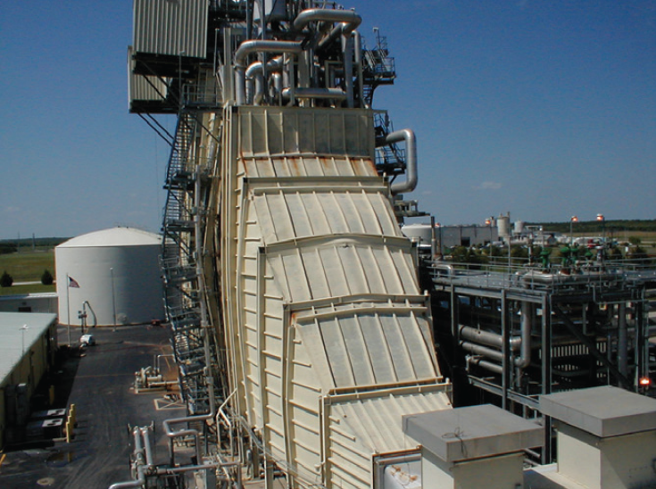
When flame was established, plus one second, the trip was inhibited but the SRV continued to open. Exhaust temperature increased but not to the over-temperature set point. The fuel/air mixture was high enough to increase the exhaust temperature, but the limited oxygen at crank speed allowed a very rich fuel/air mixture to continue through the turbine until it reached the HRSG inlet duct. The additional oxygen in the HRSG triggered an explosion, damaging the boiler (photo).
The modification suggested to prevent a failure of this type in the future was to add a 60-sec timer to the trip. The failure and modification were described in Mark V Newsletter, No. 6, Feb 13, 1995.
The engineering recommendation was detailed in Mark V Software Note, No. 98, Mar 3, 1995, thusly:
Two separate events indicate that the setting of the liquid and gas excess-fuel trips are not protecting the unit as intended. The typical setting for the liquid-fuel trip is 15% of rated fuel flow—27 gpm for an MS7001EA. If fuel flow is calculated at fire and 10% speed, it is approximately 1.2% of rated flow, 2.4 gpm. The gas setting is based on the ratio valve opening and is approximately 30%. Typical opening of the ratio valve to establish starting P2 pressure is less than 5%.
The practice for excess liquid fuel has been to depend on the over-temperature trip to protect the turbine, with the excess-fuel trip itself sensing a failure of the bypass valve after startup.
On gas fuel, the excess-fuel trip is based on the ratio-valve position and is intended to avoid the introduction of large amounts of gas if the valve were to fail open on startup.
The following modifications are recommended to use the excess-fuel trip to sense a fuel control-valve failure, closed for liquid and open for gas, and trip the turbine to avoid subjecting the turbine to an over-temperature excursion:
LIQUID FUEL. The excess-liquid-fuel trip constant LK60FFLH should be set to 5% of the 100% FSR (fuel stroke reference) fuel flow, which is the approximate flow at a warmup condition of 16% FSR and 30% speed. The excess-fuel trip rung should be modified to inhibit the trip 30 seconds after flame rather than at the completion of warmup as shown in the diagram below.
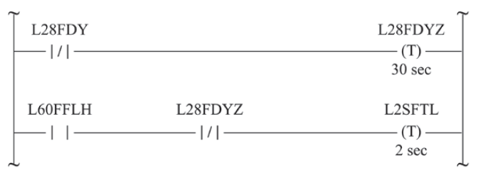 Actual operating conditions on liquid fuel, such as startup FSR values and firing speed, may vary from unit to unit. This may necessitate slightly different excess-liquid-fuel trip settings. The unit should be started and the fuel flow monitored to determine the actual flow from firing to the completion of the 30-sec L28FDYZ timer.
The excess-fuel constant should maintain a minimum 1% margin to the observed flow. Fuel flow also should be monitored on a hot start since the unit acceleration and fuel flow will be higher than on a cold start. If the observed flow exceeds the cold-start excess flow, the L28FDYZ timer should be reduced to the point at which the hot-start flow equals the excess-fuel constant minus 1%.
GAS FUEL. The excess-gas-fuel trip constant LK60FFGH should be set to 10%, which is the expected ratio-valve opening with a margin of 5%. The excess-fuel-trip rung should be modified to inhibit the trip 30 seconds after flame rather than at flame (diagram below).
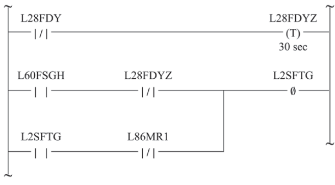
Actual operating conditions on gas fuel, such as startup FSR values and line pressure, will vary from unit to unit. This may necessitate slightly different excess-gas-fuel trip settings. The unit should be started and the position of the ratio valve monitored to determine the actual movement during firing. This value can then be used as the excess-fuel trip with a 5% margin.
The Mark V Software Note added the timer and reduced the SRV position trip from 33% to 10%.
In 2000, GE issued TIL 1275-1R1, Excessive Gas Fuel Flow at Startup, which revised the criteria for excessive gas fuel from valve position to SRV inter-valve pressure, P2. GE pointed out that several factors could affect excess fuel flow—such as leaking SRV, inter-valve vent solenoid failure, LVDT failure, and lube-oil condition, among others. The OEM recommended adding logic to detect both high and low P2 pressure. It provided a typical SRV startup position curve and recommended multipliers for low and high setpoints. A time delay for the trip was not included.
The TIL was revised in 2006 to offer P2 pressure protection software to automatically monitor P2 conditions.
A request for an opinion was recently received via a conversion from Mark V to Emerson about excess-fuel trip. Emerson proposed to add the excess-gas-fuel trip on P2 pressure. Emerson told the user that his original GE software had not been updated and to add the P2 excess-fuel sequence or the time-delay trip.
The original GE experience and solution (valve position) was provided as equivalent protection for the turbine and would be simpler to install.
Fuel Regulator units, MS3002 and MS5001, depended on over-temperature control for excess-fuel protection.
Mark I controls for MS3002, MS5001, MS5002, and MS7001 machines used the SSVA card, which only monitored differences in the servo currents and could trigger a servo fault alarm. Later, the SFUA card was introduced for liquid fuel. The card had an excess-liquid-flow trip adjustable to 15% of fuel flow.
Gas fuel used the SSVA card which monitored the closed position of the SRV and tripped the turbine if the valve opened before flame. Both trips were disabled by L28FDY, flame plus one second. Excess gas fuel depended on the over-temperature control for protection.
Mark II controls for MS3002, MS5001, MS5002, MS7001, and the LM2500 had an excess-liquid-flow trip on the SFUA card. The fuel-gas control used the SSVD card; it monitored the SRV and tripped the turbine if the valve was opened before flame. Both trips were disabled by L28FDY, flame plus one second. Excess gas fuel depended on over-temperature control for protection.
Mark IV and Mark V control systems used both liquid fuel flow and SRV position to trip on excess fuel. Several MS7001EA and MS6001B Mark IV and Mark V users were asked to verify if their excess-fuel software had been modified to include the time delay or TIL 1275. Their response:
- None of the Mark IV units had the timer modification or the reduction of the SRV position from 33% to 10%.
- Results for Mark V were varied. The Mark V Software Note position change to 10% had been applied to units sometime after 1995. However, the timer was not part of the change. Some units had the SRV position trip set to 15%. The Mark V units after 2000 had the TIL 1275 upgrade to P2 pressure which did not include the time-delay trip.
Recommendations. There have been at least four events of excess gas fuel on startup involving both MS6001 and MS7001 units with Mark IV and Mark V controls. It is probable there have been others not reported. The damage resulting from a duct or HRSG explosion can be expensive.
Users of Mark IV and Mark V controls installed prior to 2000 should check to see what protection is installed for excess gas-fuel flow. The trip logic is L2SFTG, Startup Gas Fuel Flow Excessive. The control constant for the valve position is LK60FSGH, Startup Fuel Stroke Reference High Alarm Setpoint.
The easiest change, if the position constant, LK60FSGH, is higher than 10%, would be to reset it to 10%. This will not avoid all potential failure modes, but it is better than doing nothing.
Addition of the 60-sec time delay as shown in Software Note 98 would be the second most effective protection.
The GE-recommended P2 pressure protection is effective but more difficult to install.
Since “excessive liquid fuel” is based on the actual liquid fuel flow as measured by the flow divider, it is effective protection. CCJ