![]() To understand the true value of a user group like the Generator Users Group, you must attend and participate in its collaborative, technical environment of generator experts. With the 2022 conference just one month away in San Antonio, the following intends to illustrate the unique content disseminated and absorbed by attendees.
To understand the true value of a user group like the Generator Users Group, you must attend and participate in its collaborative, technical environment of generator experts. With the 2022 conference just one month away in San Antonio, the following intends to illustrate the unique content disseminated and absorbed by attendees.
The 2021 conference of the aired back in July virtually, and like all GUG conferences, the content lives on. Presentation slide decks and many recordings by users and vendors—but not the OEMs—are available to registered owner/operators in the GUG Conference Archive section of the Power Users website at www.powerusers.org.
![]() A goal of all user groups operating under the Power Users umbrella is to disseminate technical material presented at its conferences to the managers, engineers, and technicians who would benefit most from it by improving plant performance. CCJ is working with Power Users to facilitate access to this information.
A goal of all user groups operating under the Power Users umbrella is to disseminate technical material presented at its conferences to the managers, engineers, and technicians who would benefit most from it by improving plant performance. CCJ is working with Power Users to facilitate access to this information.
Fact: Everyone is not interested in everything presented at a meeting and very few, if any, with equipment responsibilities today have the time to “pan” for information that might help them grow in their chosen profession.
CCJ and Power Users believe they can help in this regard by enabling readers to quickly locate technical material conducive to making better O&M decisions. As you read through the summaries here, bear in mind they are not intended to provide the “answers” you might be looking for, but rather point you to presentations by experts who can.
Think of this recap as a “TV Guide” of sorts for the web. To our knowledge, no one previously has provided such a service to the power industry. Now you can peruse a meeting’s content in sound bites and locate relevant details in a minute or two. Efficiency!
We apologize in advance for possibly overstepping our editorial bounds by identifying presentations we believe to be excellent for a particular reason (exceptional photos, for example). Our opinions are based on years of attendance at user-group meetings and in hallway discussions with knowledgeable plant personnel like you.
If you have any thoughts to share on our approach here, we would welcome them. Please drop an email to Scott Schwieger at scott@ccj-online.com.
User presentations
![]()
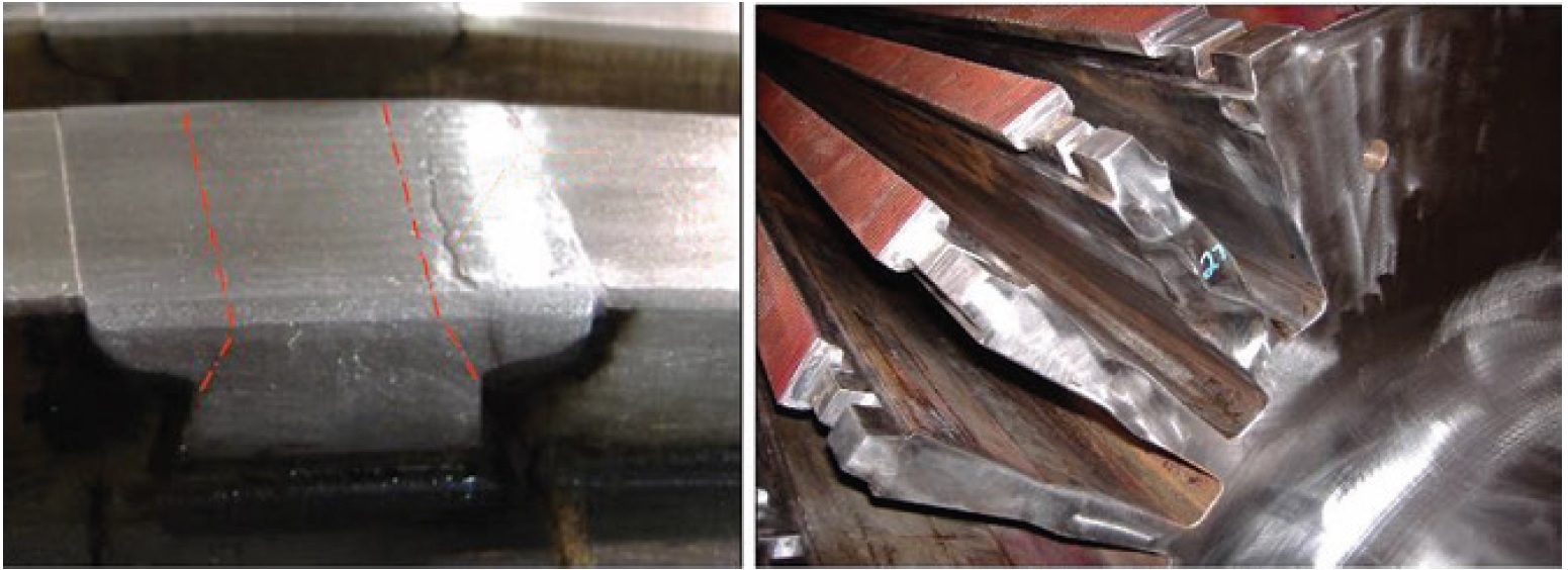
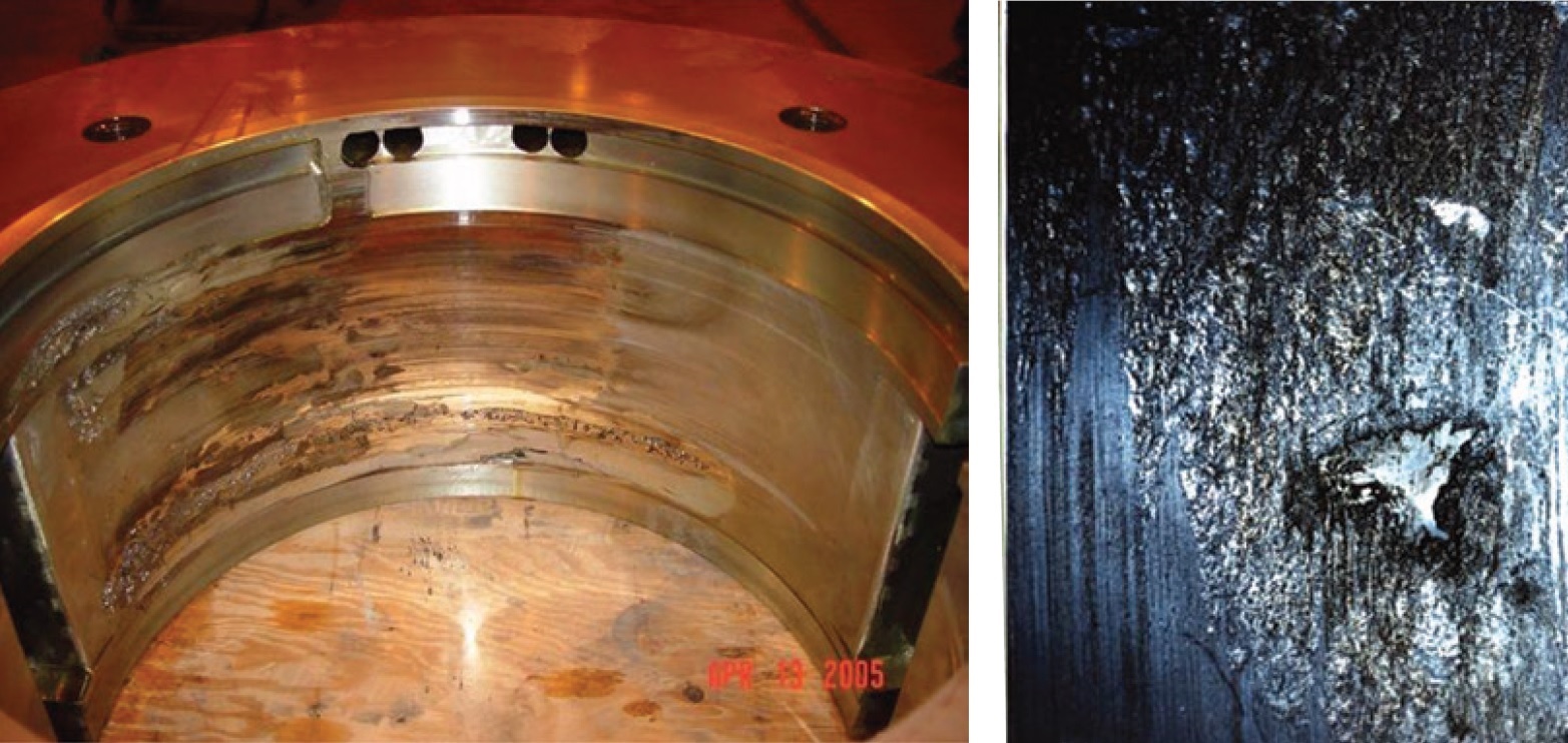
Rotor tooth-top cracking
- A valuable paper for all who have responsibilities involving rotor operation and maintenance.
- Two Westinghouse 68-MVA generators that after 42 years of moderate-duty operation were found with many serious problems—including extensive tooth-top cracking of the rotor-body forging (Fig 1, left).
- Two highly skilled engineers developed ingenious repairs (Fig 1, right) that are described with many excellent photos.
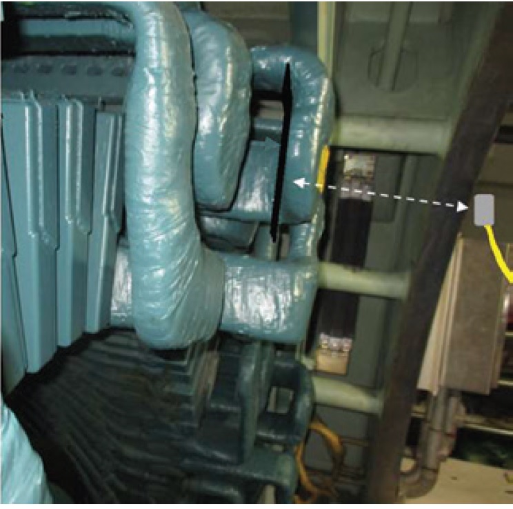
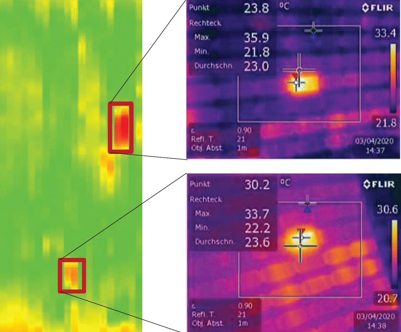
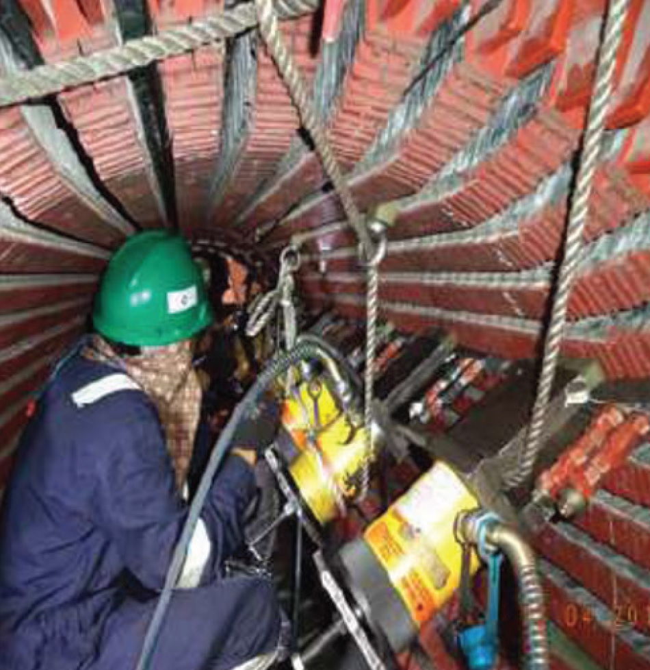
Radiographic inspection of phase straps (TIL-1965)
- Valuable and interesting study of use of radiographic inspection to replace OEM recommendation of stripping insulation to look for cracking of copper leads (Fig 2).
- Findings seem to indicate successful results: No cracks found, time and cost saving significant.
- But some complications, for example: (1) Large isolation area roped off may interfere with other work. Stripping of insulation still required if cracks found.
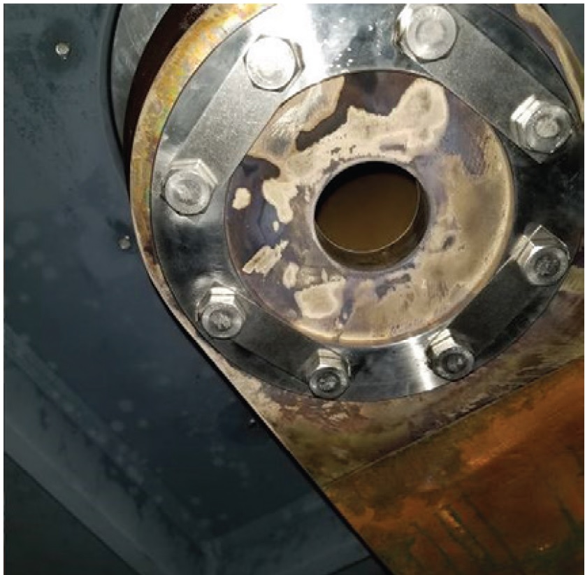
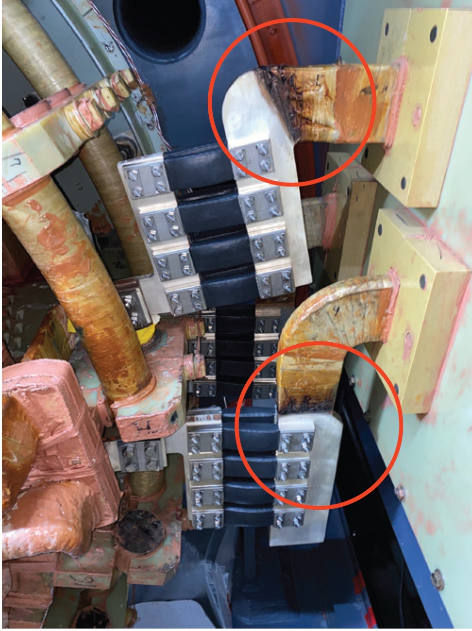
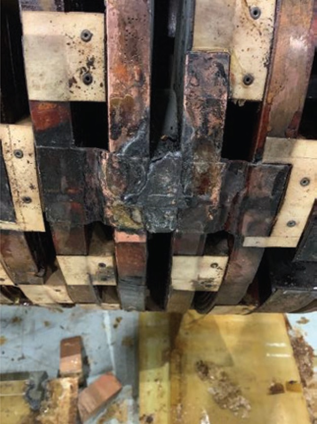
Stator-winding resistance tests: Troubleshooting and investigation
- Excellent discussion of high DLRO (digital low-resistance ohmmeter) readings found on stator winding copper:
- *One was a true reading that led to corrective action on an incorrectly assembled bolted joint (Fig 3). This action likely prevented a catastrophic failure.
- *The other was attributed to improper DLRO “homemade” leads being used.
- The message: Use care and good judgment in dealing with instrumentation readings.
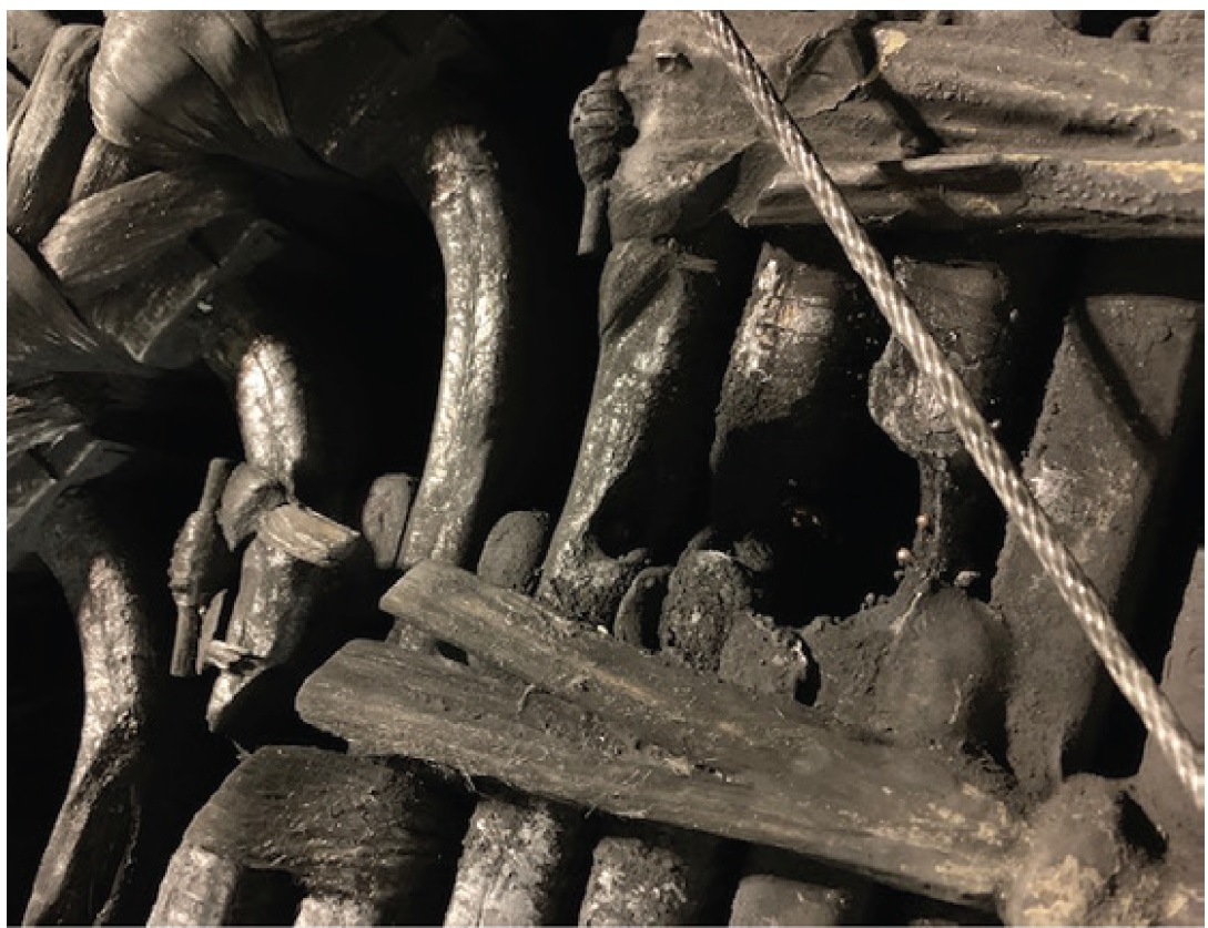
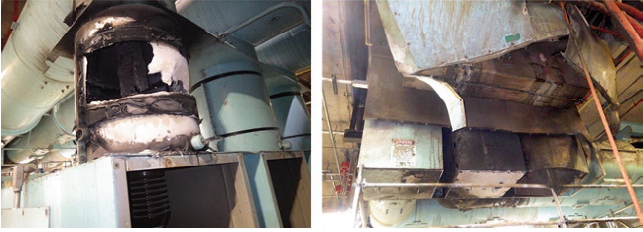
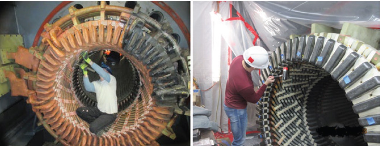
Generator failure and subsequent extent of condition inspections
- Many slides describing extensive problems (Fig 4) found on seven combined-cycle generators with only a few years of operation.
- Problems ranged from small ones, such as minor greasing in stator windings, to large ones, such as partial core restacking, stator rewinds, and field rewinds.
- An instructive presentation.
Stator-winding collateral damage resulting from an isophase-bus fault event
- A valuable, well-illustrated presentation describing an accurate analysis of a catastrophic isophase/stator-winding failure (Fig 5).
- Well worth spending some time with this presentation following the logic illustrated in the analysis and resolution of a huge event.
Vendor presentations
![]()
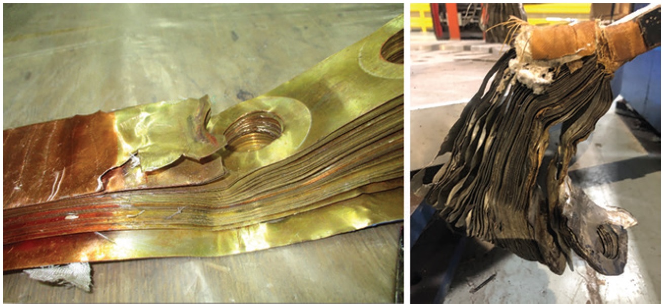
Generator-field main-lead failures, MD&A
- An excellent tutorial on field-winding main-lead design, failures (Fig 6) and repairs.
- Highly valuable reading for anyone responsible for field operation and maintenance.
- Many excellent photographs and drawings.
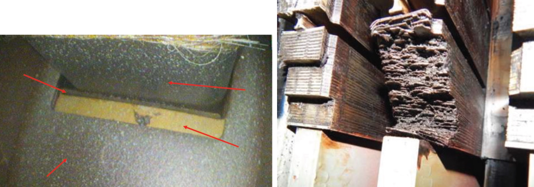
Generator-stator core looseness and failures, AGT Services Inc
- A detailed review of serious core-looseness problems on modern GE generators for large gas and steam turbines—specifically, outside space block (OSSB) migration on 390H and 450H GTs and 324 STGs (Fig 7 left); trailing-edge end-iron looseness on 7FH2s (typically on peaking/high cycling units); tooth loss on 7FH2s built by Mitsubishi Power (Fig 7 right).
- Concludes that “Modern GE stators need to be evaluated for core tightness frequently.”
- Very important reading for anyone responsible for reliability of the models of GE generators identified in the first bullet point.
Generator-stator bolted and brazed connection inspections, AGT Services Inc
- Tutorial on connection inspection, with emphasis on bolted designs.
- Many photographs illustrating good and poor connections (Fig 8).
- Valuable presentation for anyone with responsibilities relating to stator-winding reliability.
Unintended magnetism and corrective measures for improved maintenance programs and risk reduction, MPS Gaussbusters
- Comprehensive review of unintended (residual) magnetism in turbine/generator components.
- Many photos and sketches illustrating components and problems (Fig 9).
- A good presentation for anyone involved in overall equipment operation and repairs.
Generator retaining-ring failure case studies, MD&A
- Well-illustrated retaining-ring design and function tutorial. No retaining-ring failures.
- Discussion of Nomex tab rivet failures on certain GE generator designs (Fig 10).
- Some useful information for those responsible for operation and maintenance of generator fields.
Stator-core condition assessment with CPC 100, Omicron
- Good tutorial on stator design, duties, and fault measurement (Fig 11).
- Emphasis on measurement with CPC 100 and at higher frequency, 400 Hz.
- Valuable presentation for anyone with responsibilities for stator-core maintenance.
Rewind versus repair when commercial and technical aspects are diametrically opposed, National Electric Coil
- Detailed summary of decision process, commercial versus technical, on two stator winding failures.
- Details of the cleaning and repair work are well illustrated (Fig 12).
- Valuable reading for plant personnel responsible for generator maintenance.
Successfully rewinding GVPI generator stators, National Electric Coil
- Valuable semi-tutorial presentation on rewinding of GVPI stators (Fig 13).
- Discussion of relative merits of GVPI vs hard-coil windings.
- Useful presentation for anyone with responsibilities relating to generators.
DIG DEEPER: SAN ANTONIO, AUGUST 28 – SEPTEMBER 1