
With the 2023 Generator Users Group (GUG) approaching August 28-31 in Atlanta, part of the greater Power Users Combined Conference, reviewing some of the content from last year’s meeting should encourage you to attend or send someone from your organization to experience this valuable content in person. Presentation abstracts below are based on information available only to end users in the slide decks posted at www.powerusers.org. Those seeking deeper dives into specific topics should note the presentation titles in italics at the end of each summary and access the source material on the website.
Fixators: What you should know about them
User group meetings are a great place to learn from the industry’s top talent in the owner/operator, vendor, and consultant communities. Information shared may include new regulatory initiatives and how they could impact plant operations, findings by colleagues that might affect your facility as well, case histories of importance, and backgrounders on equipment and components of significance that you might know little about.
At the 2022 GUG meeting, several backgrounders received high marks from attendees—including one on fixators (Fig 3), a continuously adjustable alignment wedge assembly for machine mounting. Important to recognize is that fixators are not shims, and the speaker presented a table comparing the two.
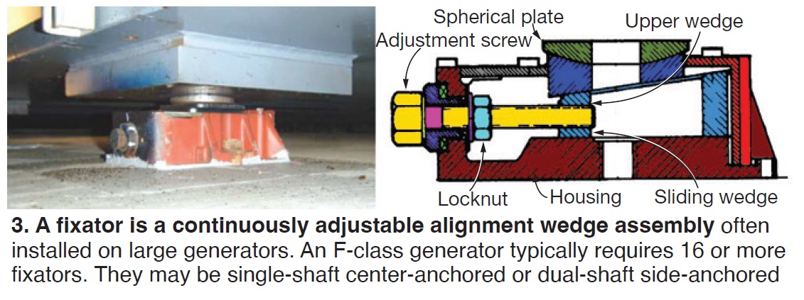
Suppliers of fixators claim they allow faster alignments than shims on new installations because you avoid the need for jacking up a machine, installing the shims, and then lowering the machine to check if it is level. If not, the process is repeated until the result is satisfactory.
Leveling and alignment by way of fixators is much simpler: For initial leveling, turn the adjustment screws a couple of turns and check. If not level, repeat. For alignment, identify the low points among the 16 or more fixators that might be installed on an F-class generator and raise to the degree necessary using the adjustment screws.
The presenter said his company had fixator issues on about 10% of its generators so equipped. Most often, vibration—sometimes attributed to a soft foot—was the underlying cause. Three case histories give the details.
Given fixator adjustments may be required over the life of your generator, experts recommend inspecting them at every turbine major, minor, and hot-gas-path inspection and cleaning and lubricating as required. Be prepared: Some fixators might have to be replaced.
“Fixators: Not as Fixed as You’d Expect”
Keeping flex links in top condition helps promote generator reliability
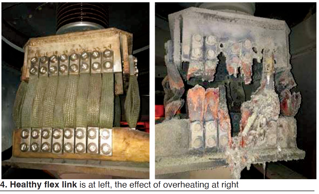
Flexible links provide an electrical connection between two rigidly mounted conductors, thereby allowing relative thermal growth/movement between them. Links may be of the laminated, wire-braid (Fig 4 left), and wire-rope type. Common locations include (1) between generator terminals and isolated-phase bus, (2) main leads and bushings, (3) connection rings and main leads, and (4) neutral bushings or Y point.
Common issues include the following:
- Mechanical failure attributed to (1) broken wires or laminations caused by fatigue or fretting, (2) incorrect installation, and (3) material creep/deformation.
- Overheating (Fig 4 right) caused by loose hardware, poor mating surfaces, and/or corrosion; poor ventilation; marginal connection or hardware design.
- Inattention to installation/maintenance best practices. It’s important to digest OEM bulletins, properly torque connection bolts, maintain a high level of cleanliness, follow OEM procedures to the letter, etc.
Causes of three flexible-link failures are described in detail in the slide deck. Plus, corrective and preventive actions are provided for each. This is “not difficult stuff.” It’s all about learning the correct way to install and maintain your equipment and staying committed to the task at hand.
Owner, OEM, industry colleagues, user group share info to resolve main-lead issue
Unplanned outages of a particular generator model traced to failures of main leads experienced by several owner/operators were a topic of discussion on the GUG and IGTC (International Generator Technical Community) forums early in 2021. Users were concerned because the failures occurred within months of the OEM performing NDEs that indicated the main leads were fine.
The OEM responded within a few months, recommending replacement of the main leads. The most likely cause, it said, was copper separation at the main-lead flange braze joint which could result in a generator ground fault and damage to surrounding components. The improved main-lead design offered has a more robust joint between the main-lead flange and the main-lead conduit.
The presenter said his company has eight of the 49 affected units and that no failures had occurred at any of its sites. An NDE inspection at one plant revealed no findings. The owner’s concern was the hefty hit on its budget if all of the susceptible main leads were replaced. Plus, there was a 45-week lead time associated with the OEM’s repair.
Have a look at the slide deck to see how the owner developed its own repair with help from industry colleagues to upgrade its main leads, saving time and money in the process.
“Main and Neutral Leads Mod for Modular Units”
What grounding-brush issues may be telling you
Shaft grounding can be accomplished by using a carbon brush, soft metal-bristled brush, or soft metal strap (often braided) to ride on the shaft surface and safely discharge voltages which can build up within the shaft train. The author explains where shaft voltages come from and what 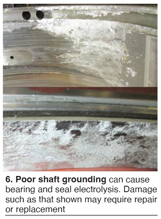 happens when a shaft grounding brush (SGB) malfunctions (it could cause a nuisance trip).
Next comes a series of slides that explain how you can identify a malfunction before it impacts operations—for example:
- High shaft voltage.
- No/low shaft brush current.
- Bearing and seal electrolysis. Fig 6 shows that this damage is “real,” possibly requiring repair or replacement. Vibration conducive to a forced outage also is a possibility.
- Magnetization of components.
- Artificial vibration. An orbital plot of this phenomenon is included.
Artificial rotor-winding ground indication. Point made: Online rotor-winding-to-ground resistance measurements may be influenced by induced voltage.
Users are advised to check brushes weekly for functionality or need for replacement. Responsible persons should be alerted if a significant SGB event occurs or recurring minor events are experienced. Also, check turbine and generator parts and rotors for residual magnetism; degauss down to 2 G or less, if possible.