


McIntosh Power Plant is home to the first W501G gas turbine to experience a turbine-rotor through-bolt failure. The utility worked closely with OEM Siemens to complete an investigation to determine the failure mechanism. While this lengthy process unfolded, the utility invested in several mitigation efforts to minimize the potential for future through-bolt failures. This best practice focuses on one of the mitigation actions—dehumidification—and lists other ideas that were implemented.
There had not been a turbine through-bolt failure in more than 30 years of operating gas turbines of essentially the same design. Therefore, starting from scratch on a root-cause analysis (RCA), early indications pointed to a high stress riser at the Row-1 disc area, where the fracture occurred (Fig 2). An in-depth investigation of all significant materials provided important facts regarding the incident but did not identify a sole root cause.
The theory was that moisture in the rotor air cooler (RAC) circuit could be carrying debris to the Row-1 disc area and creating a debris pack between the rotor and disc. Based on the concern for moisture and debris in the RAC circuit, Lakeland Electric (LE) researched possible mitigation efforts and implemented the most promising.
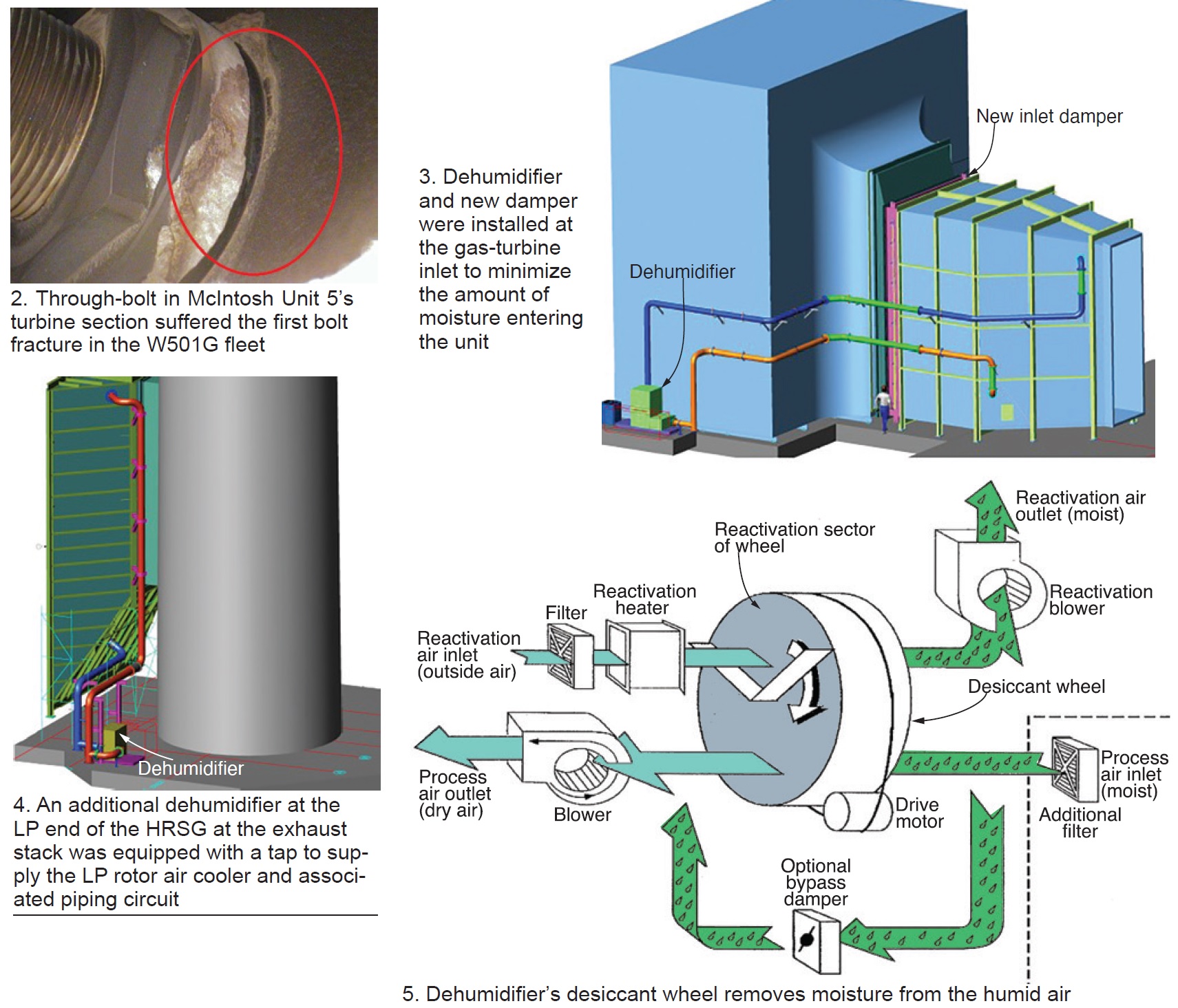
The utility’s first initiative, to eliminate the sources of moisture in the RAC circuit, was to engineer a dehumidifier application for the gas-turbine inlet and add a damper to minimize moisture from entering via the GT inlet (Fig 3). LE also added a dehumidifier to the LP end of the HRSG at the exhaust stack with a tap to feed the LP RAC and associated piping circuit (Fig 4). A damper was not required at the stack because one had been installed previously.
When Unit 5 was brought offline, the new damper allowed LE to “bottle up” the unit. Then the dehumidifiers would be placed into service to help prevent moisture from condensing because of the humid Florida air. This prevented the RAC piping from sweating, creating moisture, and causing corrosion in the RAC piping circuit.
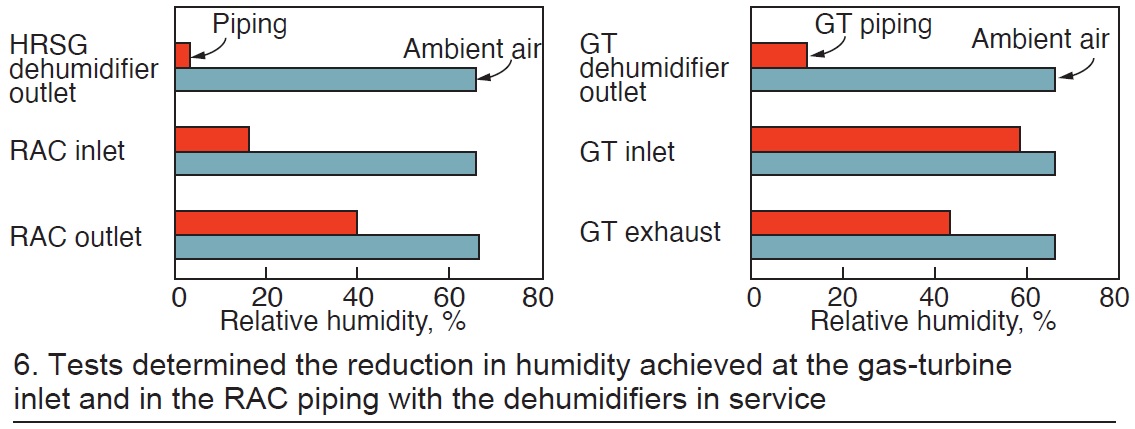
Fig 5 shows how the dehumidifiers work. They are equipped with a desiccant wheel to remove moisture from the humid air; desiccant reactivation is by application of heat to the wheel. Tests were performed to determine the reduction in inlet and RAC-piping humidity. Fig 6 provides test results to illustrate dehumidifier effectiveness.
Other mitigation efforts also were initiated to help control moisture and corrosion in the RAC piping circuit, thereby protecting the rotor through bolts—including the following:
- Developed a hydro procedure for RAC leak inspections and repairs (outage standard).
- Added a thermocouple to the RAC to detect water from a leak. This point was brought back to the plant DCS.
- Added RAC manual drains that are checked during startup of Unit 5.
- Automated the RAC drains to open during turbine startup to blow any moisture to the blowdown tank.
- Installed an additional RAC startup strainer.
- Changed the RAC piping from carbon steel to stainless to eliminate debris.
These enhancements enabled a cleaner RAC circuit and less debris transport to the turbine rotor.
Use of an investigative process enabled LE to implement multiple solutions for reducing moisture and debris from the RAC piping circuit. Specifically:
- The utility implemented solutions developed by its personnel—including Kevin Robinson, operations manager; Guy Tayler, mechanical engineer; and Steve Reinhart, plant manager—and several by Siemens engineers as noted in the list above.
- Siemens eventually redesigned its 501G rotor through bolts and Lakeland has implemented the latest OEM technology and rotor through-bolt design in its rotor upgrade program.
These shared technology advancements have been implemented throughout the W501G fleet and there have not been any rotor through-bolt failures since.

