![]()
The Legacy Turbine Users Group, formed by Power Users earlier this year to facilitate the transfer of knowledge among members of the 7EA and Frame 5 and 6B users groups, greatly benefits owner/operators of these engines. The 7EA’s first meeting under the LTUG banner, conducted Aug 29 – Sept 1, 2022, was an unqualified success and will be reviewed in an upcoming issue.
Here the editors present the highlights of the 2021 7EA conference, which you may have missed because of the pandemic, and salute the staffs of the Lincoln Generating Facility and Crete Energy Venture, both powered by 7EAs, for their success in CCJ’s Best Practices Awards program. The presentations reviewed below are available user access through the conference archives at www.powerusers.org.
The 7EA Users Group has been serving owner/operators of GE Model 7EA, A, B, C, and E gas turbines for more than a quarter of a century. Today, the OEM refers to this group of units collectively as 7E, a naming convention which can be confusing to some plant personnel.
A bit of history. The first two Frame 7 package power plants (PPP)—the lingo used by GE decades ago for its gas turbine/generators “packaged” for rapid deployment where power was needed—were ordered by Long Island Lighting Co and installed in the summer of 1971—one at the utility’s West Babylon plant, the other at its Shoreham Plant (a/k/a Wading River).
The nominal 52-MW distillate-fired units were still in standby service and equipped with their original Mark I Speedtronic™ control systems when the editors contacted National Grid, the current asset owner, last year.
Today, there are roughly 1200 7Es (new GE designation) in service worldwide—three-quarters of them are 7EAs.
7EAUG Steering committee, 2022
Dale Anderson, East Kentucky Power Co-op
Joshua Coots, Duke Energy
Tracy Dreymala, EthosEnergy Group, San Jacinto Peakers
Jeff Hansen, Old Dominion Electric Co-op
Guy LeBlanc, IHI Power Services Corp
Tony Ostlund, Puget Sound Energy
Mike Vonallmen, Clarksdale Public Utilities
Lane Watson, FM Global Chemical Operations
User presentations
Lessons from the field: Circuit-breaker maintenance practices
Breaker events profiled in this slide deck, available to registered users at www.powerusers.org include the following:
- New breaker failure at a 7E simple-cycle plant.
- Vacuum-bottle failure at a hydro plant.
- Catastrophic breaker overheating.
- Single-pole failure of a 115-kV breaker.
The takeaways from these events provide valuable “lessons learned.” For the first, the presenters’ experience confirmed that modern relaying can be of considerable help in speeding-up troubleshooting after an electrical trip. The second showed vacuum bottles have a finite life. More specifically, dc hipot/bottle integrity tests do not give an indication of future life.
Takeaway from No. 3, illustrated with circuit and logic diagrams, and photos of damage: Breaker forced-cooling apparatus is important if it’s applied. Action items: Act on alarms, check runback levels, maintain cooling fans, and correct failing switches. Important: Spare breakers can be a life-saver.
High-side/substation breaker reliability is critical, attendees were told. Ensure the plant, or transmission utility, is providing proper maintenance and upgrades. Review your Generation Interconnection Agreement regarding responsibilities—if your plant has one. In any case, proper and regular maintenance must be performed on all components to ensure reliability.
Guidance on the maintenance required is provided, along with the timing of tests, what good results look like, and data interpretation. Bear in mind that roughly half of all breaker performance failures are attributed to lubricant degradation, improper selection, and/or misapplication.
A lunch-and-learn session in the plant break room might be in order to familiarize staff with breaker assembly and components, troubleshooting, spare parts, the importance of proper bolt torquing, and where to find the breaker manuals when they’re needed.
In-situ fuel-nozzle flow testing
Presenters describe positive results in using a portable air-flow test stand (PATS), a/k/a portable flow bench, to conduct fuel-nozzle testing in-situ rather than removing fuel nozzles from the gas turbine and sending them to a shop for that purpose. Important point: This owner has a fleet of well over a hundred gas turbines.
The PATS was said to provide a direct measurement of the engine’s fuel-nozzle characteristics, with the ability to isolate the problem to a single combustor position/circuit and possibly eliminating fuel-nozzle flow as a cause of the issue being dealt with. Several slides describe how PATS works and the infrastructure support required to conduct testing—for example, more than 80 cfm of clean, dry air.
Case studies are summarized for the following engines:
- 501FD2 (DLN)—high blade-path spreads, with cold spot.
- 7F (DLN 2.6)—high exhaust spreads after an outage, with cold spot.
- 7EA—high exhaust spreads after a liquid-fuel run, with cold spot.
- 7EA (DLN 1)—high exhaust spreads after an outage, with no hot/cold spot.
In closing, the speakers shared what challenges colleagues might encounter with in-situ flow testing, including these:
- Access to air of the quantity and quality required.
- Possible limitations of PATS given ambient-air characteristics where used (not a controlled repair-shop environment).
- Not all combustion issues can be solved with flow testing.
- Easier when fuel-nozzle flow targets are available to compare to “spec.”
Vendor presentations
What we are seeing in the 7EA fleet during our inspections
Advanced Turbine Support
The 2021 version of this annual presentation by Mike Hoogsteden, the company’s director of field services, which is of significant value to plant personnel for its many illustrations, highlighted GE Technical Information Letters (TIL) users should become familiar with, in particular—including the following:
- TIL-1854, “Compressor Rotor Stages 2 and 3 Tip Loss,” suggests blending and tipping to mitigate the impact on availability and reliability of Row 2 and/or R3 tip loss.
- TIL-1884, “7EA R1/S1 Inspection Recommendations,” addresses the need to inspect R1 and S1 airfoils for possible damage caused by clashing—the unwanted contact between the leading edges of S1 stator-vane tips and the trailing edges of rotor blades in the platform area.
- TIL-1980, “7EA S1 Suction Side Inspection Recommendations,” advises users to inspect for crack indications on S1 vanes made of Type-403 stainless steel, regardless of whether clashing damage is in evidence on S1 and R1 airfoils or not.
- TIL1562-R1, “Heavy-Duty Gas Turbine Shim Migration and Loss,” informs users on the need to monitor the condition of compressor shims and correction actions available to mitigate the risks of migrating shims.
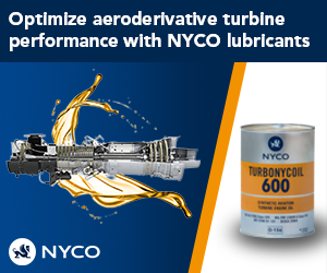
Compressor stator-vane looseness: What to look for and what to do
CTTS (a/k/a Core Tech)
Pinning is a relatively low-cost and quick solution for gas-turbine owner/operators challenged by compressor stator-vane looseness. More than 200 engines have been “pinned” in the last 20 years, avoiding engine damage and saving thousands of vanes (Fig 1).
The pinning technique, developed by Rodger Anderson, who began his career as a member of GE Frame 7 compressor design team, has been the subject of several CCJ articles over the years. What to look for during your next compressor inspection in terms of shim migration and vane looseness/damage is described in the slide deck along with the likely causes.
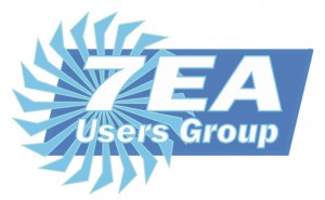
Emergency rotor support services—a case study
Sulzer
The borescope inspection of a simple-cycle 7F unit revealed severe damage in compressor rows 14 through the exit guide vanes (Fig 2 left). The owner/operator needed the unit back in service ASAP. Presentation slides detail the steps taken to assure proper corrective action—from inspection to rotor disassembly to parts replacement with shop-manufactured components to reassembly (Fig 2 right) to rotor balancing to preparation for shipment to the plant—in only 36 days.
Details presented in the slides provide a valuable learning experience for the plant team. The second part of the presentation gives details on Sulzer’s capabilities, repair history, shop capabilities, rotor life assessments, and field services.
Analysis of inspection protocols for S-1/R-1 clashing
Veracity Technology Solutions
The goal of an inspection protocol should be to provide the highest sensitivity for flaw detection and determine an inspection frequency that gives the inspector the most opportunities to detect a flaw before the defect becomes catastrophic.
In the example given, two units were undergoing their annual NDE inspections to satisfy the requirements of TIL-1884 (see first item above). The units were equipped with C450 stators, which exhibited signs of corrosion lockup in the lower half after nearly 11,000 fired hours and 2000 starts. An eddy-current inspection was specified; a fluorescent penetration inspection was conducted as well to validate the findings.
Many indications were identified and are shown in the slides. Analysis revealed the cracks emanated from shallow surface discontinuities which experts believe were caused by one or more of the following: environmental conditions, possible stress corrosion cracking, and high-cycle fatigue (from stator lockup in the vane carrier).
Conclusions: The use of traditional penetrant methods may not be effective for detecting the types of cracks found. Only after the stators were removed and sent to the shop did the inspection team identify all of the flaws using its proprietary inspection technique.
It’s important to note that swapping out of the Type-C403 stainless-steel stators installed on older machines with C450 components recommended by the OEM may not provide the level of asset protection desired. The bottom line: It’s imperative to be diligent on your inspection protocol.
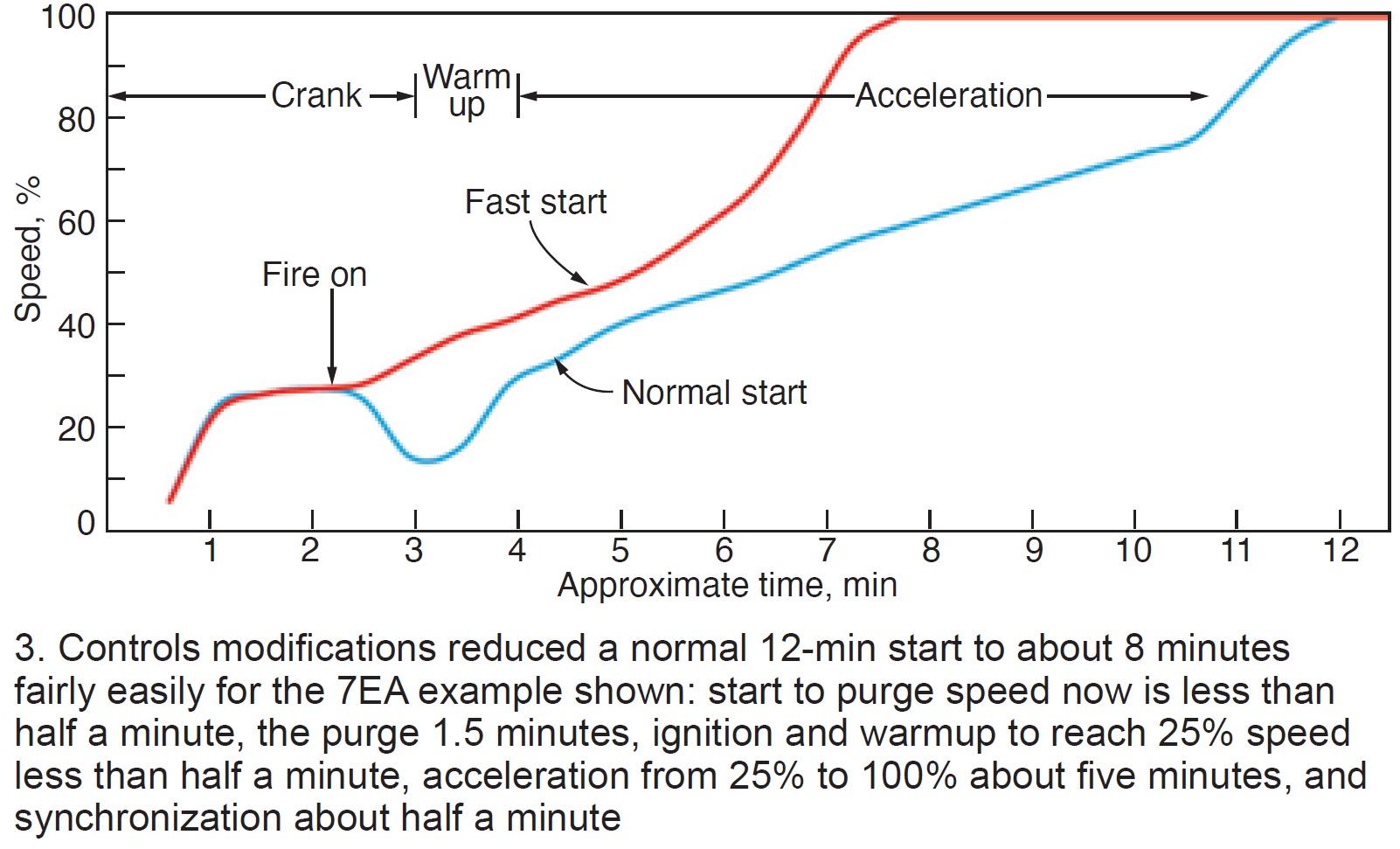
Getting your 7EA ready for increased run time
Emerson
If you’re looking for a checklist of action items to improve the run times of your units, reading through this presentation is a good place to start. It focuses on controls mods, generally far less costly than hardware changes, to consider. Example: Control mods can enable the transition from normal to fast starts (Fig 3).
Bus maintenance in action
RMS Energy
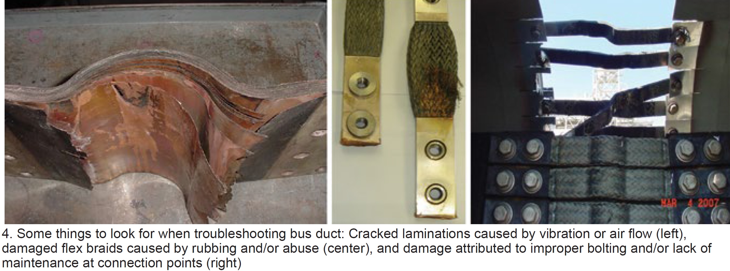
Bus duct is relatively easy to maintain. Keep it dry, clean, and cool, the RMS Energy experts say, and your problems will be minimal. But how many plant personnel do you see walking around outside and looking up? And even if they were, the upper portion of the duct remains out of sight.
The presentation begins with a list of critical bus-duct components: Flex/bolted connections (current carrying), expansion bellows/joints, insulators and mountings, seal-off bushings, grounding, and insulated joints. Fig 4 shows some of the damage one can expect without a rigorous monitoring/inspection plan.
Monitoring equipment/techniques suggested include these: Thermocouples and infra-view camera to monitor components remotely and initiate alarms. Electromagnetic signature analysis (EMSA) is a valuable online diagnostic technology that can support maintenance decisions based on real-time operating conditions. It can save critical shutdown time by eliminating the need for offline testing.
Several case studies with before/after photos are instructive.
The GTC quick solutions package
GTC Control Solutions
Five case studies encompass this presentation; four are explained below.
The first describes a single point of failure. Problem: A high differential among ambient-temperature thermocouples (t/cs) was causing a “not ready to start” situation. There were two compounding issues: The first was sub-optimal location of the t/cs. This second: A “no high differential” was a start permissive—that is, a high differential would result in a “not ready to start” condition.
The fix: Two t/cs were relocated to prevent erroneous temperature measurements. Plus, the “no high differential logic” as a permissive to start was changed to “two out of three t/cs failed.” The latter assures that if one t/c fails, operators receive an alarm but will still remain ready to start; two failed t/cs interrupt the start sequence.
Case 2 involved an LM5000, which has two speed pick-ups per shaft. Originally, the “Hi-Select” determined speed. Thus, one failed hi-detector trips the unit. Solution was to check inputs and reject “out-of-limit” values.
Case 3 involved an LM2500 with very hot starts. Over-temperature trips occurred during startups. Diagnostic alarms indicated a loss of P2 pressure feedback. Solution was a logic change to “IF on temperature control during startup THEN trip.”
Case 4 described problems with a 7B gas turbine equipped with torque converter, jaw clutch, and limit switch that experienced starting difficulty. Clutch disengaged at 47% speed; however, logic required clutch to remain engaged until 50% speed. Torque converter degradation was the problem and the logic was changed to permit clutch disengagement below 50% speed.
Gas-turbine operability challenges in an unstable grid environment
EthosEnergy
Chris Chandler, chief technologist for turbine optimization, warned attendees that recent grid-wide reliability events in California (summer 2020 ) and Texas (calamitous winter freeze 2021) were likely to be experienced nationwide as the percentage of renewables on grids keeps growing. Because gas turbines and combined cycles will be expected to “pick up the megawatt slack” when renewables output drops by hundreds, and even thousands, of megawatts precipitously, combined cycles need to adapt for operation at the “lowest sustainable limit” (LSL).
Balance of Chandler’s presentation explains how the company’s Ecomax Extended Turndown optimization package can extend the life of the equipment while operating more hours at LSL. It addresses the consequences of operating at prolonged maximum turndown states, most importantly the inability of the HRSG to adequately attemperate and higher CO production from the combustor.
Operators are alerted in real time what the LSL is and the Ecomax Extended Turndown “knobs” are used to operate at that point until CO becomes an issue. The system can boost GT output by 5 to 15 MW per unit at the low end, says Chandler. As of this presentation last year, the concepts had been validated and the program was in commercial development with a lead user.
7EA turndown solutions: How low can we go?
PSM
Presentation is a good review of PSM’s tools for extending engine turndown. It begins with a review of the company’s LEC-III™ ultra-low emissions and LEC-NextGen combustion systems and refreshes your recollection of its inlet bleed heat and exhaust bleed solutions.
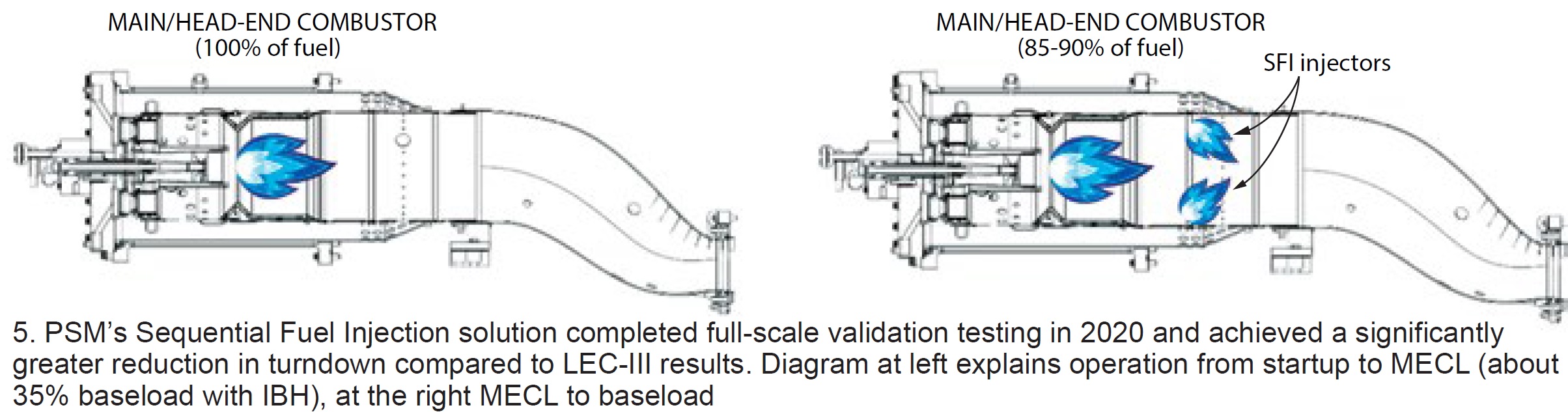
PSM’s latest turndown solution—Sequential Fuel Injection (SFI)—specifically engineered for 7E (that is, Models 7B through 7EA) LEC and DLN 1 combustion systems is the presentation’s focus. SFI is said to leverage prior sequential combustion experience with the company’s FlameSheet™ product, to achieve comparable results with SFI without major changes to existing combustion hardware (Fig 5).
Recall that low-emission combustors are sized for optimum NOx emissions at baseload and “lean-out” as load is reduced; CO spikes as the Minimum Emissions Compliant Load (MECL) is approached. With SFI, the main/head-end combustor is sized for CO at MECL, and SFI fuel is added proportionally as load is increased from MECL to baseload (up to 15% of the total).
SFI fuel reacts with hot excess air from the main/head-end combustor, holding the temperature rise in check, thereby minimizing NOx production while also maintaining low CO.
Remote operations for simple-cycle GT sites
Emerson
Lots of things to think about if your simple-cycle unit is not yet equipped for remote operation. Presentation’s stated goal is to help users leverage digital transformation to save O&M and increase earnings.
Using flow net modeling to optimize fuel-nozzle calibration and flow testing
Trinity Turbine Technology
New ideas for optimizing combustion-system air and gas mixing to reduce emissions and temperature spreads. Results have been promising; work continues.
Emergency material and design support
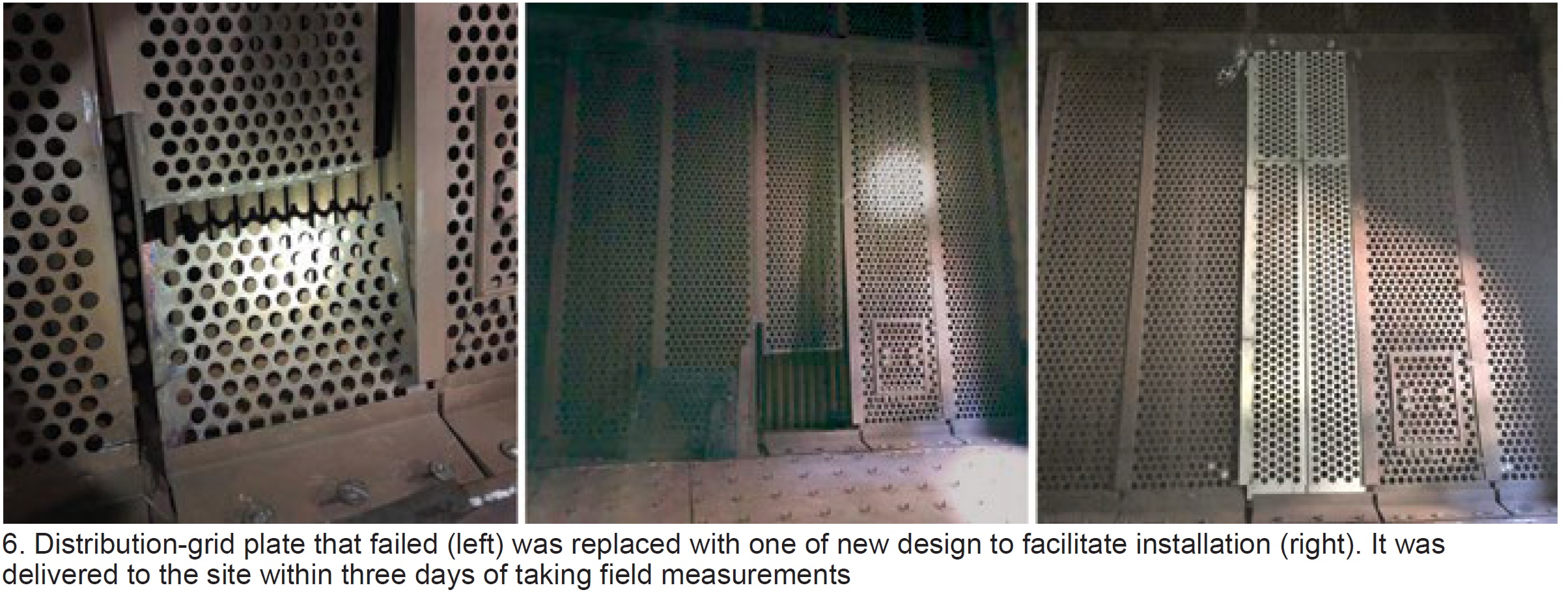
Schock Manufacturing
Slide deck focuses on Schock Manufacturing’s ability to respond quickly to customer problems—such as expansion-joint blowout, exhaust-liner sheet failure, diverter damper seat and landing-bar failures, failed trash screens, stack corrosion, failure of silencer panels, etc (Fig 6). Customer testimonials are included.
Generator testing: What the tests mean and how they are resolved
AGT Services Inc
Jamie Clark had a simple objective here: Identify standard tests and inspections—electrical, mechanical, and visual—that plant personnel should be familiar with to avoid operational surprises and to assure the highest level of equipment reliability possible. He provided examples of both bad and good test results, and offered recommendations and corrective actions to achieve the stated objective.
Here’s the lineup of components Clark recommends inspecting:
- Stator winding: Endwinding support system, wedge system, gas-gap baffle studs, rubber baffles, and bushing box for hydrogen-cooled machines.
- Stator core: Tightness, iron migration, damaged/overheated laminations, and vent duct blockage.
- Field (rotor): Cleanliness, arcing between wedges, hot spots on tooth tip at wedge joints, retaining-ring condition, borescope look under retaining rings, collector-ring condition, fan damage, and copper dusting.
This is a good presentation for a lunch-and-learn in the plant break room. Details are at a minimum, photographs are excellent.
Considerations for the fleet management of gas-turbine lubricants
EPT Clean Oil
Company specializes in ion-exchange-based lubricant treatments and oil testing in critical applications. It maintains an on-going R&D program focused on advancing the science of lubricant management.
Peter Dufresne’s goal was to help owner/operators see the value in treating their lubricants as an asset, rather than as a consumable, and to understand and use the tools at their disposal to manage that asset. Here’s an “executive summary” of the plan he suggests users follow. Details are in the 49-slide PowerPoint.
- Complete oil analysis done to ASTM standards.
-
- Track and monitor rates of additive consumption.
- Predict end of lubricant life well in advance.
-
- Use a conditioning system to manage oxidation.
-
- Eliminate potential for varnish and reduce rates of additive consumption.
-
- Purchase high-quality oils from a reputable manufacturer/supplier.
-
- Consider an annual 5% top-up.
-
Lincoln, Crete earn Best Practices Awards
Peaking plants Lincoln Generating and Crete Energy Venture were the only facilities in the 7EA fleet recognized for their best practices in 2021 (details below). Interestingly, both are operated by Consolidated Asset Management Services LLC (CAMS) and managed by Brad Keaton, facilitating the sharing of best practices for maximum impact. Lincoln, located in Manhattan, Ill, has eight simple-cycle units, Crete, located in Crete, Ill, four.
Safety, reliability foremost when purchasing a mobile fall-protection system
Several locations at Lincoln Generating Facility and Crete Energy Venture required fall protection where no adequate tie-off points were available. One of the most notable: Generator circuit-breaker platforms at Lincoln (Figs 7 and 8). When performing generator breaker work from the platform, personnel had adequate fall protection. However, the work often required climbing up to a higher level, which exposed workers to a fall risk and therefore the need for fall-protection harnesses.
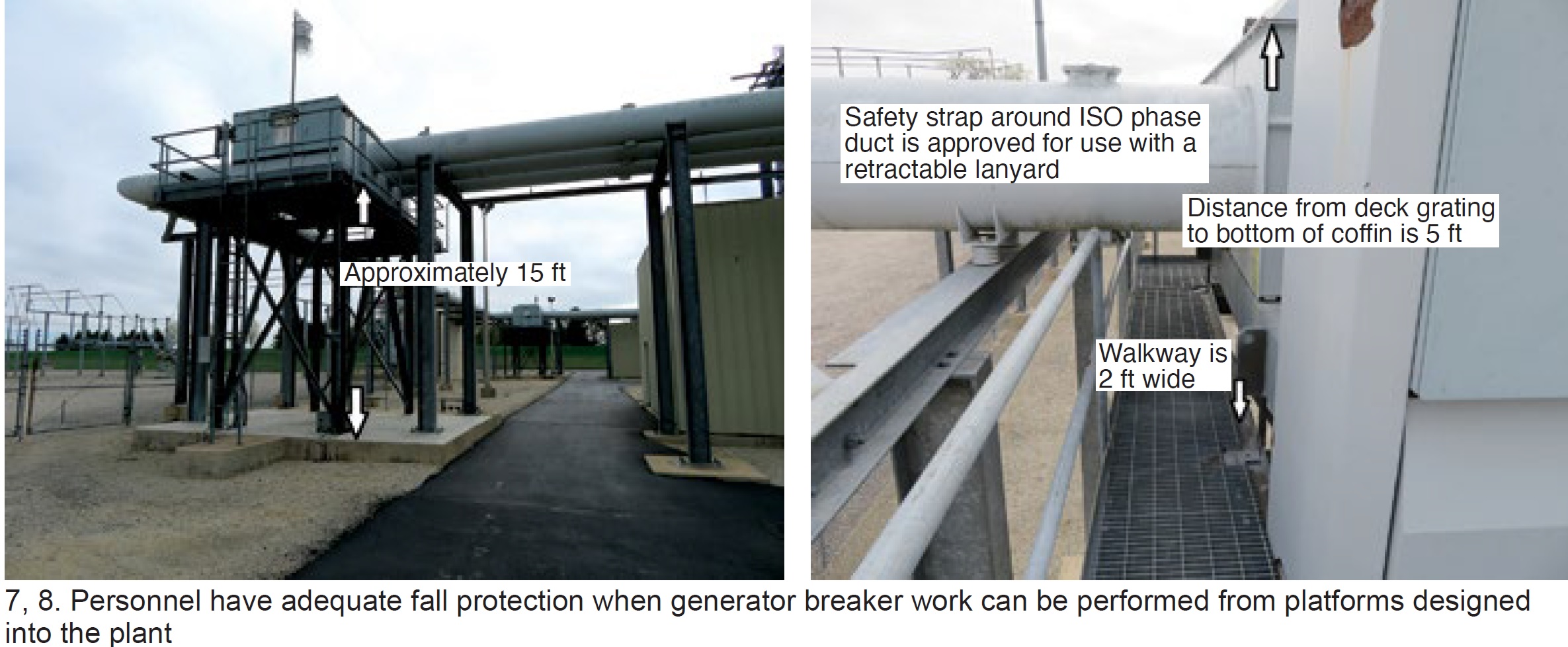 A problem arises when the technician is standing on the highest point in the area and is only able to tie off to the equipment that he/she is standing on. If the person were to fall to the platform below, the fall protection would not work, because the drop is less than the distance required to fully engage the fall-arrest lanyard, but it’s still high enough to cause serious injury.
If the technician fell off the structure entirely, the fall-arrest equipment would come into play; however, there is a possibility of injury by the fall-arrest system because of the distance the worker would drop before activation.
Lincoln staff explored numerous options over the years to eliminate the fall risk described—including temporary scaffolding during planned maintenance, which was not practical when required for unexpected issues forcing the unit into an outage. Permanently installed tie-off points proved costly because of their installation and periodic testing requirements.
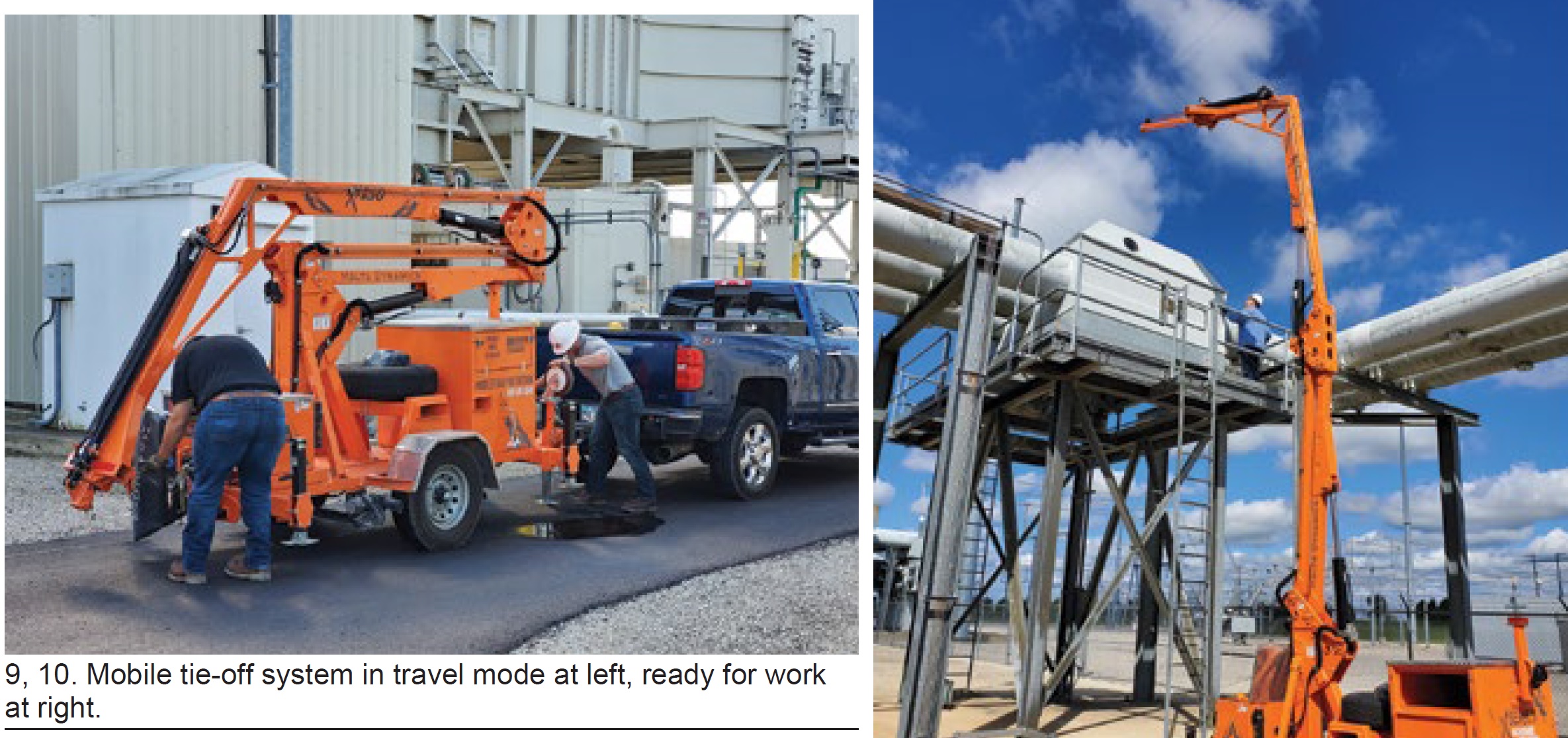
Personnel observed a demonstration of an OSHA-approved mobile tie-off system, which could be used in many different locations at Lincoln, and shared with Crete (Figs 9 and 10). The system demonstrated had tie-off points for three workers. It received owner approval and an OSHA-approved system was purchased.
The mobile tie-off system has been used successfully in many locations at Lincoln and Crete. Its proven benefits include the following:
- Cost was half that for permanently installed systems considered for just the generator circuit-breaker platforms.
- The mobile system has tie-off points for three workers, which is adequate for the work scopes plant personnel perform.
- Scheduling and coordination of temporary scaffolding during outages is no longer required.
- Staff now is capable of safely performing emergency repairs.
Mark V lifecycle, reliability improvements produce dramatic results
Crete Energy Venture, commissioned two decades ago during the gas-turbine boom, was experiencing challenges with obsolescence, parts availability, and OEM support. This was especially true for the Mark V gas-turbine control system. OEM declarations ceasing production support of system components in 2014, outdated HMI interfaces and hardware, limited OEM training offerings, plus the wear and tear of daily operation, led staff to investigate methods for the continued reliable operation of the control system.
After performing their due diligence, it became clear to plant management that a full control-system upgrade was not necessary, as multiple third-party vendors provide solutions for parts repair/replacement and field service support, and the functionality of the TMR (triple modular redundant) Mark V controls remained robust. Staff determined that multiple methods of improvement were available for a comprehensive control-system reliability program and implemented the following solutions:
Mark V health checks. Since 2016, Crete has hired a third-party vendor on a biennial interval to perform reliability assessments of the Mark V control panels and associated equipment. It identified numerous issues lingering below the surface which eventually could have caused forced outages if not addressed.
Mark V cards, ribbon cables, and instruments have been replaced proactively during the assessments, and bad wiring terminations in remote junction boxes have been corrected. The permanent clearing of what could be considered nuisance Mark V diagnostic process alarms and dc-equipment grounding issues also was a site priority during the process. Result: The plant now experiences significantly fewer unplanned equipment failures than previously.
Inventory management. After the initial increase in site inventory and the addition of firmware revision-specific spares—such as EEPROMs (electrically erasable programmable read-only memory)—plant personnel continued to discuss optimized plant inventory levels for each Mark V card and component during every reliability assessment.
Increased inventory levels of high-use/high-failure-rate boards, like the TCEA and TCPS, have proved beneficial on multiple occasions, reducing downtime during controls-related upsets. Crete also replaced the GE TCPS power-supply boards with an upgraded aftermarket version from GTC Control Solutions after experiencing a failure or alarm condition that predicted future issues. Any used card, or one of unknown condition, that may have been replaced during troubleshooting also is sent to an outside vendor for a condition assessment and in-panel test to ensure that all site inventory is functional upon installation.
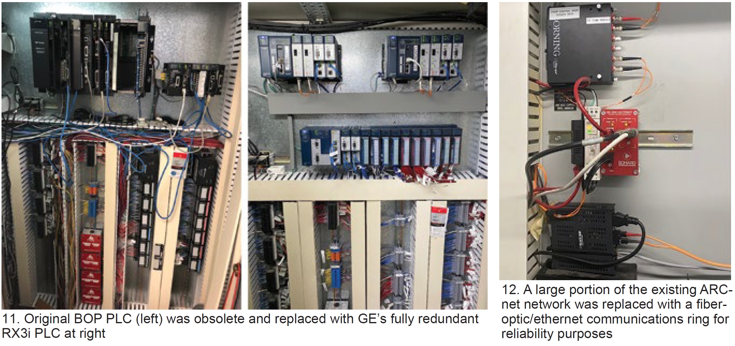
BOP PLC upgrade. The original installation used an obsolete pairing of GE Fanuc 90-70 and 90-30 PLCs—each with limited parts availability, single CPUs, and the need for a no-longer-supported Genius Bus Module communications device (Fig 11 left). Personnel determined that because of obsolescence, single-point-failure risk, and limited forward compatibility, this PLC should be replaced. The latest product offering from GE was selected and a fully redundant RX3i PLC was installed by Innovative Werks in fall 2019 (Fig 11 right).
HMI upgrade. The site’s OEM Cimplicity HMI servers were a major point of concern when assessing overall reliability, cybersecurity, and functionality of the turbine control system. Continued hardware issues required extensive man-hours for monthly server backups and re-boots to prevent server and ARCnet lockups. Plus, the Windows XP platform had long been obsolete, increasing cybersecurity vulnerability.
Additionally, the existing system had only one Mark V server in the control room and one in Unit 2’s packaged electrical and electronics control center (PEECC), limiting access to logic forcing, signal name, and TC2K reports, as well as to more advanced Mark V engineering and diagnostic tools.
Crete contacted TTS Energy Services to install a redundant server TMOS HMI system in May 2020. The Traffic Management Operating System eliminated a large portion of the existing ARCnet network and replaced it with a fiberoptic/ethernet communications ring, removing a costly and long-lead-time failure point from the control network (Fig 12). Recall that Cimplicity HMI ARCnet cards are proprietary and difficult to source.
This system also did not require any modification or head-end upgrades to the Mark V control panels, making it a very cost-effective solution. The new network topology includes a client HMI workstation in each of the plant’s four PEECCs and the control room, giving technicians full access to the Mark V control screens and engineering tools in all locations.
Easier access to dynamic point logic, trends, and signal names/values directly from the control screen provides a more intuitive operator interface, allowing for reduced troubleshooting time during abnormal plant operating events and a more simplistic training process. It also provided the site with state-of-the-art Windows Server 2019 and Windows 10 operating systems. Continued patching and Windows support for these machines allow Crete to maintain a high cybersecurity standard on the controls network.
While each of the aforementioned projects individually would have had a positive impact on the lifecycle of the existing Mark V controls system, Crete has seen marked improvements in hardware reliability and system functionality after implementing the full program. Mark V card replacements, when required, typically are done proactively, rather than reactively.
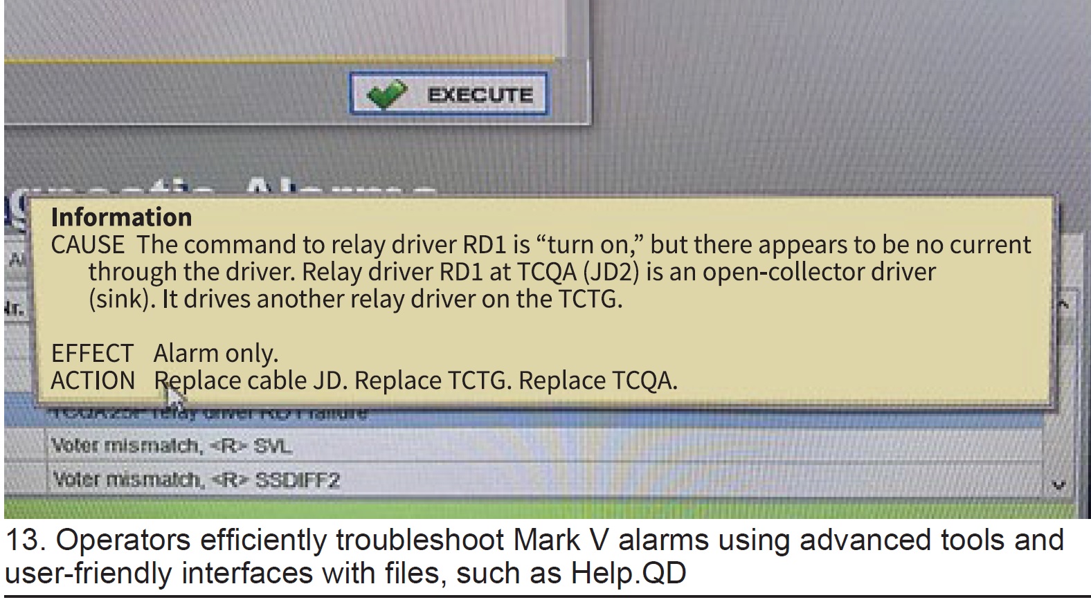
Operators are able to efficiently troubleshoot Mark V alarms using advanced tools and user-friendly interfaces with files such as Help.QD (Fig 13) and direct click access to dynamic logic rungs. Technicians learning Mark V can be trained on specific tasks with ease, removing the tedious and time-intensive process of learning and perfecting the exact syntax and terminology used in command prompt.
Additionally, the TMOS came quipped with a historian, giving personnel access to higher-resolution operating data without requiring a View 2 file to be running to capture operating events.
With the process improvements described, and with resources in place, site personnel are confident they can continue reliable and sustainable operations with the Mark V control system for many years to come.
LED lighting upgrades make for safer maintenance, operation
With a staff of three, the Crete site continuously explores methods for optimizing maintenance activities and eliminating high-man-hour tasks that don’t directly contribute to the site’s high standard for safety, reliability, and availability. While evaluating the facility’s equipment condition and the man-hour contribution of different systems, staff determined that a significant amount of time was being spent on changing MCC indicator lights and fluorescent building lights. Plus, a man-lift rental was required annually for street-lamp replacement.
Constant lighting failures also presented a safety concern, because failed indicator-lamp sockets can cause confusion on equipment operating status. Plus, plus, ergonomic constraints for replacing other fixtures increased hazard exposure. Considering these issues, as well as the potential to improve energy cost efficiency and reduce hazardous waste generation, plant personnel pursued an alternative, and simple, solution.
Advances in LED lighting technology afford industrial facilities the opportunity to upgrade lighting cost-effectively. Plant personnel researched product offerings and found solutions for the majority of the site’s lighting fixtures. Outdoor high-intensity-discharge (HID) lamps were replaced with LED equivalents expected to reach more than 94,500 hours of useful life with vastly improved light dispersion and output.
MCC indicator lights and sockets in the PEECCs were replaced with relampable LED fixtures that have a much brighter display and required no modifications to wiring or bucket mounting. The control building, switchgear building, PEECCs, generator breaker cabinets, and accessory gears all were retrofitted with LED lighting solutions over the last three years.
Today, the only remaining non-LED lights onsite are the turbine-compartment and fuel-gas-module lamps because there are relatively few product offerings that can withstand the operating conditions and/or regulatory requirements for hazardous atmospheres.
After the lighting upgrades, the man-hours required to replace failed lighting has been reduced from about 200 hours annually to fewer than 20. Hazardous waste generation related to lighting (as well as universal waste from ballasts) has virtually been eliminated because all remaining non-LED fixtures are incandescent bulbs. The improvements to site safety also are notable, as better work-area lighting and reduced hazard exposure are in line with Crete’s commitment to employee safety and continuous process improvement.