

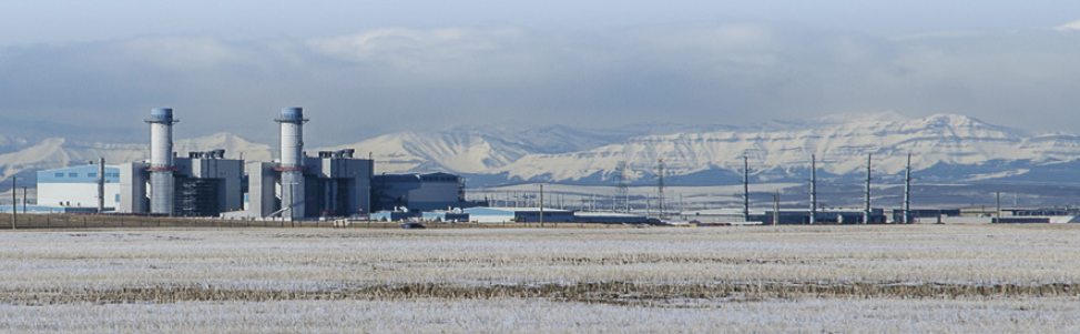
Shepard Energy Centre
Owned by Enmax and Capital Power
Operated by NAES Corp
860-MW, gas-fired, 2 × 1 combined cycle powered by M501G1 gas turbines and located in Calgary, Alta, Canada
Plant manager: Terence Dumonceau
Challenge. To protect against ice formation on inlet guide vanes (IGVs) and Row 1 compressor blades during cold-weather operation, the plant was designed with inlet glycol heating and a compressor bleed air system (Fig 1).

Early in the plant’s operation, staff observed that during low ambient temperatures and high humidity conditions, ice would form on the leading edge of the finned glycol heating coils. The gas-turbine control system limited the compressor bleed air system to operation at part load, thereby preventing the system from assisting with icing issues at base load. Even at part load, the nozzle distribution and resulting flow pattern were only able to prevent ice from forming in localized areas downstream of each nozzle.
To prevent the ice from choking air flow to the gas turbine (Fig 2), the plant operations team scraped the face of the glycol heating coils. This had to be done continuously until the ambient conditions changed. Such events were experienced on a weekly basis over the course of the winter, with a typical event lasting between two and eight hours. In severe conditions, scraping was unable to mitigate the ice formation and the gas turbines would be derated.
Over the first three winters of operation, 6.3 GWh were lost because of derates, with an estimated 56 GWh of cumulative derates avoided by the scraping efforts of O&M personnel. Plus, to mitigate icing, the heating coils often were operated at full capacity which increased the gas-turbine inlet temperature by up to 22 deg F above ambient and significantly reduced gas-turbine output. And as these events were related to cold weather, they would coincide with high power prices, which magnified the impact to the plant.
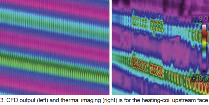
Solution. To further understand the issue and begin working toward a resolution, the plant commissioned a study to assess design documentation, review historical operating data, conduct a site survey, collect field data, and perform CFD modeling (Fig 3). It found the root cause of the glycol coil icing to be the materials of construction. The original coils were made of stainless steel having a poor thermal conductivity. CFD modeling showed that the temperature of the leading edges of the fins were expected to increase by only about 4 deg F above that of the ambient air. Issue identified, multiple options were proposed for permanent resolution.
Option 1: Swap the glycol flow direction from counterflow to parallel flow.
Calculations proved this method to be ineffective. Limited by the thermal conductivity of the stainless steel, even providing hot glycol to the front face of the heating coil was predicted to only result in a 7 deg F increase above ambient.
Option 2: Install an infrared heating system upstream of the glycol heating coils.
Although technically feasible, the high implementation cost and significant electrical load requirement of 600 kW per unit was difficult to justify.
Option 3: Revise control logic to enable use of compressor bleed air at base load.
Control logic changes were evaluated with the gas-turbine OEM. However, use of the bleed air system at base load was not desirable as the primary resolution because of its negative impact on output and heat rate. To properly mitigate the icing issue, the nozzle arrangement and resulting flow pattern would have to be addressed as well.
Option 4: Replace the existing heating coils with ones of copper/aluminum construction.
Despite the coils not being designed for replacement, a cost/benefit analysis supported this as the preferred option.
Implementation. A specification was developed for the replacement heating coils which included copper tubes and aluminum fins with a protective coating. The replacement coils were then procured though a public bid process.
In parallel, the plant team prepared for the complex task of swapping the heating coils through development of a detailed installation plan. This plan was executed during a scheduled gas-turbine outage, which included engineered scaffolding, mobile crane, jack-and-roll system, and over 2000 man-hours. All 12 coils (six left-hand and six right-hand) were safely replaced on schedule within a six-day window.
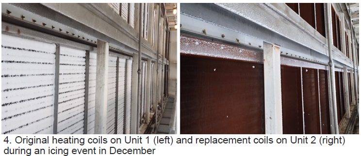
Results. The performance of the new coils has been validated during multiple icing events (Fig 4). The project has a forecasted payback period of less than five years. With the observed success, the plant is currently proceeding with plans to complete the heating coil replacement on its second gas turbine.
Project participants: Mike Sterling and Shane Bucar, with support from AAF and Camfil.

