![]()
If the coronavirus pandemic has taught us one thing, having the ability to access the expert information needed to perform O&M tasks at the highest level without leaving the plant (or home) is vital. With good internet connections generally available at most powerplants, the challenge might be finding the information required. You likely have several preferred websites to search, ones that may have helped you in the past.
If CCJ not one of them consider adding it to your “preferred websites” list. Our online library, keyword searchable on the homepage, can direct you to perhaps unimagined resources on the operation and maintenance of gas turbines and combined cycles. Included among these resources is our webinar library.
At home you might access a service such as Netflix for leisure viewing; at work search CCJ’s webinar library for guidance on how to identify and implement critical O&M solutions capable of helping you and your colleagues improve plant safety, availability, and performance.
To learn more about the library and its value for your facility, please skim the content summaries below of webinars conducted in the last few months and use the links provided to watch one or two. No charge! Note that several more online conferences and webinars are scheduled before year-end—including the 2020 meetings of the 7EA, Steam Turbine, Generator, Combined Cycle, and Power Plant Control Users Groups.
CONCO
Every owner/operator of a plant with an air-cooled condenser (ACC) might benefit from listening to Gary Fischer on the value of an ongoing condition-assessment program and how the experts find performance-robbing leaks quickly. His presentation is fast-moving, easy for both new and experienced employees to understand, and answers the question, “Why do we not want to try doing this with plant personnel?”
![]()
Fischer begins with several slides on the importance of cleanliness, the sources of fouling, and how to remove external deposits (Fig 1). The free flow of air across all heat-transfer surfaces is critical, the chairman of the ASME Heat Transfer Committee reminds. A 20% reduction in air flow because of fouling and debris nestled in an ACC’s finned tubes will increase turbine backpressure by 33%, decreasing electrical output and reducing revenue.
Pushing fans to their maximum to reduce the impact of fouling is not a solution. It only exacerbates the negative impact on financials because auxiliary load increases and you wind up consuming more power at a time when you’re making less money.
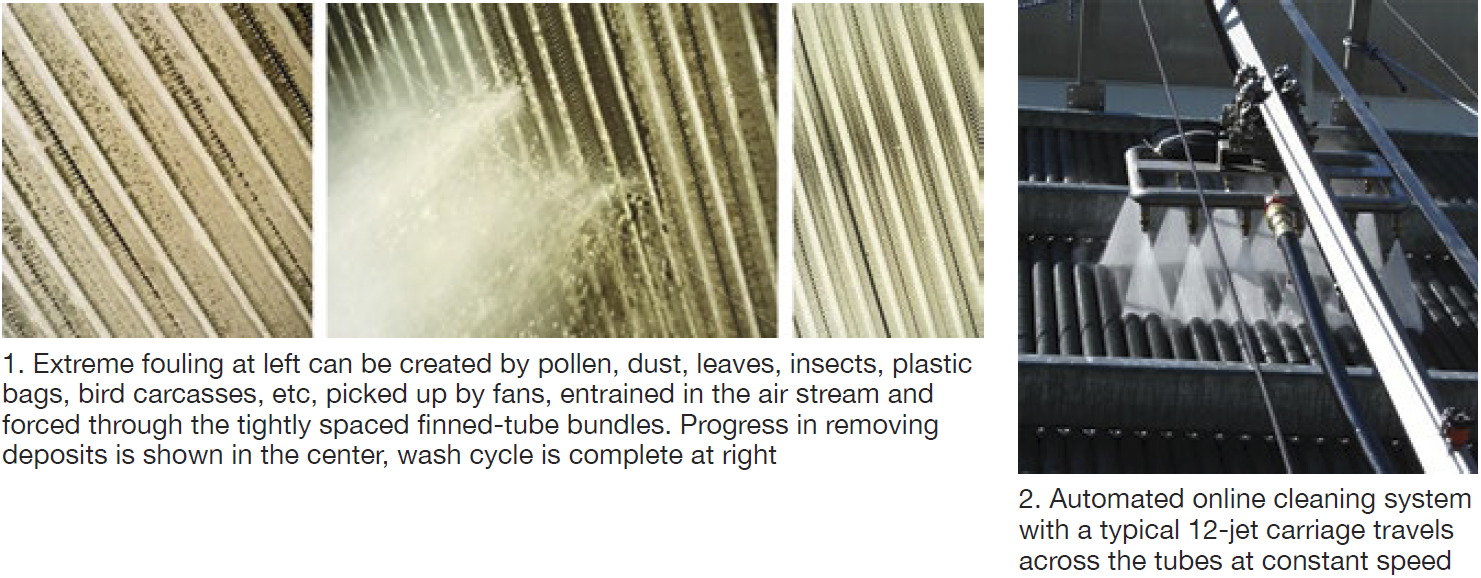 Fischer dismisses the use of fire hoses (too much water, minimal cleaning effect) and high-pressure hand lances (damage to fins and galvanized surfaces) in short order and touts the value of automated cleaning (tight process control, uniform cleaning, no need for scaffolding).
Automated online cleaning systems, such as that shown in Fig 2, have the advantage of delivering a high volume of water at a pressure that will not damage fin and tube surfaces; plus no scaffolding is required. A focused array of water jets mounted on a trolley distributes water deep into the bundle with the opportunity to adjust the jets to optimize the washing effect. The typical carriage holds a nominal one-dozen jets and travels at constant speed across the tubes, assuring effective cleaning in one or two passes.
Testing for and minimizing air in-leakage was the focus of the second part of Fischer’s presentation. For identifying the source of air in-leakage, he says non-hazardous helium wins hands-down. Detection is quick and reliable for most leaks at 1 part in 10 million above background (5 ppm). Perspective: Sometimes you’re looking for a leak less than the size of a dime in a surface area equivalent to three or four football fields. Helium can help you find that.
Oftentimes leaks are not where an inexperienced person might believe they are. A leak can be outside the ACC proper and in the hogger or hogger exhaust, the gland-seal drain/trap, the crossover bellows, or at welds in retrofit projects, etc. Don’t be surprised to find an air leak in a new unit, Fischer adds. Indicators of in-leakage are high backpressure, dissolved oxygen, and continuous hogger use.
Concludes Fischer, tracer-gas leak detection is a very cost-effective method for maintaining Rankine cycle efficiency where ACCs are installed.
CECO Environmental
The presentation by Vaughan Watson and Jeff Broderick is suggested viewing by users looking to come up to date on SCR technology and peer into the future of emissions control. The presenters speak to the following technologies and applications from CECO that they consider “next generation”:
-
- Rapid Advantage SCR (RASCR™).
- Urea as an SCR reagent.
- Direct injection.
- EDGE® ammonia injection grid (AIG).
RASCR, Watson and Broderick say, can be adapted easily to an existing plant to maximize SCR performance. It uses fuel as the heat source for reagent vaporization, rather than an electric heater, thereby promoting rapid compliance with permitted NOx emissions during unit starts and transients. Emissions compliance reportedly is achieved within 30 minutes of a gas-turbine start, typically in less than 15 minutes. Natural gas or oil can be used as the heat source for all reagent solutions, including urea.
![]()
Retrofits can be installed during a short outage. RASCR integrates with the existing ammonia vapor discharge line and the fuel supply system. Today’s low natural-gas prices typically offer an ROI in six months or less based on the reduction in parasitic power consumption.
Webinar attendees provided these facts related to NOx control at their facilities:
-
- Seventy percent of the participants said their plants have duct burners upstream of the SCR.
- The heat source for ammonia vaporization was electric 59% of the time, gas 28%.
- Fourteen of the plants polled were using RASCR technology, including five on HRSGs.
Reagent options for SCR systems are anhydrous ammonia, 99.95% pure NH3 stored as a liquid under pressure; aqueous ammonia, typically 19% to 29% NH3 by weight and stored as a liquid under pressure; and aqueous urea, a mixture of urea powder and water in solutions containing 32% to 50% urea with storage in an atmospheric tank. Recall that safety risks are associated with ammonia, not urea.
Urea may be making a comeback as a safe alternative to ammonia, the speakers say. If you’re not familiar with the reagent, be aware that it is corrosive and must be stored in tanks made of stainless steel or FRP (double-wall recommended). Piping and pump materials of construction, and seals, also must be compatible with the fluid.
Plants using anhydrous or aqueous ammonia as the reagent for their SCRs can be made more safe by converting to urea. In the case of anhydrous ammonia, the conversion to aqueous ammonia or urea requires addition of a fluid handling skid and vaporizer system. A new storage tank also may be required depending on its condition, capacity, etc. Going from aqueous ammonia to urea will require a stainless steel or FRP tank and possibly changes to the fluid handling system regarding materials compatibility. Plus, vaporizer capacity probably will have to be increased as urea decomposition requires more energy than ammonia vaporization.
Direct injection is a method for supplying ammonia vapor to the SCR system gas path without need for a vaporization system or AIG. Its advantages include lower capital and operating costs, primarily because there’s less equipment. Photos, case history, and data tables presented by the speakers make listening to the presentation beneficial.
EDGE. Participants learned that CECO’s new AIG lance with a square (instead of circular) profile is designed and optimized to provide the desired reagent distribution across the duct to assure expected SCR efficiency and performance. The square cross section promotes better mixing, thereby improving NOx reduction, reducing ammonia slip, promoting longer catalyst life, and reducing the cost of operation. The likelihood of AIG fouling and plugging also is reduced because EDGE provides a place for deposits to accumulate without plugging the nozzles.
Explanatory drawings, lab flow-test results illustrating the degree of mixing achieved, and a case history provided in the presentation attest to the product’s success in the field.
EthosEnergy
You can run longer: What to do when your GE gas turbine is reaching the designed rotor end-of-life limit, Kale Dreymala, gas-turbine rotor project manager, EthosEnergy Group.
 If your plant is equipped with a GE industrial gas turbine—Frame 3, 5, 6, 7 (A, B, C, E, EA, and/or F)—and mention of the OEM’s Technical Information Letter 1576, “Gas Turbine Rotor Inspections,” does not strike a responsive chord, obtain a copy today from your plant’s GE representative.
TIL-1576, released in 2007 and updated in 2011 (1576-R1), identifies the equipment and personnel risks associated with operating gas-turbine rotors beyond 200,000 factored fired (FF) hours (144,000 for F-class units) or 5000 FF starts, whichever comes first, when specific intervals are not defined.
This TIL refers you to GER-3620 for overall guidance on centerline maintenance that the OEM recommends. The latest version of 3620 is Rev N, issued in November 2017. You can obtain a copy with a simple Google search. Rev N is important because it considers the impact of forced cooling on rotor inspection calculations (pages 30 to 35 and Fig 45), replacing the “trip from load factor” in earlier versions of the document.
Kale Dreymala walked webinar participants through the inspection scope recommended by EthosEnergy Group (EEG) for turbine wheels, distance piece/spacers/stub shaft, and compressor wheels. Here’s the lineup of inspections typically recommended:
Compressor and turbine wheels
-
- Visual inspection of all surfaces.
- Semi-automated phased-array ultrasonic (UT) inspection of the bore, web, and rim areas.
- Semi-automated eddy current (ET) inspection of the through-bolt holes.
- 100% ET inspection of the dovetail serrations in the compressor wheels and the fir-tree serrations in the turbine wheels.
Distance piece, spacers, stub shaft
-
- Visual inspection of all surfaces.
- Semi-automated ET inspection of the through-bolt holes.
- Semi-automated phased-array UT of the bore.
Other inspections
-
- Hardness.
- Replication.
- Dimensional measurements.
If these inspections produce no findings, the rotor is reassembled with new bolts and your engine receives a certification for an additional 50,000 FFH (one time only).
If there are findings, the speaker says the OEM is likely to suggest buying a new rotor or possibly a replacement wheel or disc, if that is the life-limiting part.
By contrast, an affordable aftermarket solution suggested by EEG probably would be to obtain a used rotor with a documented history and refurbish it in the shop. The additional life certified (from 50,000 to 200,000 FFH) depends on an engineering review. Note that for peaking units, no extensions are allowed beyond the 5000-starts limit.
Dreymala went on to describe EEG’s capability for manufacture and qualification of new rotor components as might be required during the refurbishment process get the best balance between cost and additional life. Other rotor options also were presented during the webinar, which was not recorded for post-presentation viewing. However, you can write the speaker with questions and/or for a copy of his presentation at kale.dreymala@ethosenergygroup.com.
Nitto
Depending on the type of generator cooling at your plant, and the gas-turbine fuel, a fool-proof hydrogen leak-detection program can be critical to protecting employees, the environment, critical equipment, and the overall business. This presentation presents details, data, and results of field trials of a pipe flange tape, developed for NASA, that changes color in the presence of hydrogen (photos). Thus, it provides a visual indication of a leak because it will not return to its original color once hydrogen gas flow stops.
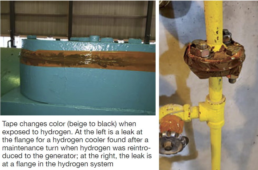
The presentation shows that soap tests typically used to find hydrogen leaks may not deliver consistent results and provide the confidence that connections/joints are not leaking. In field trials at one utility, 38 flanges were taped. All had been soap-checked prior to using the tape. Once installed, the tape on four flanges changed color within two days. The tape was removed from the flanges and the joints were soap-checked again. Only one of the leaks was large enough to cause bubbling visible to the eye.
![]()
Plant personnel concluded that the hydrogen-detection tape worked well as a pre-emptive safety check and has stimulated proactive thinking about previously unrecognized problems. Use of the tape is now part of the plant’s hydrogen-system restoration procedure following generator maintenance.
TRS Services
If you’re involved in gas-turbine repair planning, the editors suggest you listen to the presentation by Greg McAuley and Pete Sobieski, both highly experienced in the planning and conduct of turbine repairs. Each spent a decade or more with a gas-turbine OEM and two or more decades with a major owner/operator before getting back together again at TRS and expanding the company’s mission.
Today, TRS offers turbine component repairs, new-parts manufacture, and consulting services aimed at reducing downtime, minimizing total costs, and enabling new opportunities. The outcomes expected from the company’s work: reduced downtime, fewer unexpected errors, lower costs, and less hassle.
The presenters define repair planning as the process of defining the tasks important to know with a high degree of certainty what components should be retired or repaired, and to achieve the lowest lifecycle cost for parts that should and must be repaired.
McAuley and Sobieski say the five essential ingredients to successful repair planning are the following:
-
- Focus on lifecycle costs.
- Know parts pedigrees.
- Have a fallout plan.
- Choose the right partners.
- Start execution early.
They discussed each of these in turn. For lifecycle cost analysis, the speakers provide calculational examples for repairs to transition pieces and R1 ring segments, with service hours a primary variable. The results might startle you; certainly, they illustrate why this is a very important step in project cost control.
Know your parts illustrates the level of expertise necessary for an accurate evaluation of in-service components. Prior to making a repair decision the speakers say you should know lifecycle costs, hours/starts since last repair, visual appearance, repair history, the OEM’s part expectations, industry experience with a similar part. Of course, your personal experience with the repair of a similar part also is important to the evaluation.
![]()
A helpful takeaway tool is the partner evaluation process which offers a price/value comparison across the partner options entered into the equation. A discussion on contingency planning and an action plan to mitigate fallout risk.
EthosEnergy
Improve availability and reduce costs? Your data knows how. . ., Brady Kirkwood, technical services manager for EthosEnergy Group’s monitoring and diagnostics department.
Brady Kirkwood covered short-term (performance analytics) and long-term (advanced predictive AI) methods of how to identify degraded systems and provide quantifiable potential performance gains. Having the tools to evaluate the cost versus benefit of individual system upgrades/repairs to plant systems is critical to improving performance with today’s limited maintenance budgets.
The speaker provides profiles of real events resolved by EEG, including these:
-
- Hidden problem with inlet fogging causing a reduction in plant output.
- An OEM “repaired” bearing oil leak causing compressor fouling.
- Slow degradation in turbine performance during a period of high demand.
- Forced outages caused by lean blowouts.
- Fouling of inlet filters caused by the increased particulate loading attributed to forest fires.
Two goals of the presentation are to identify hidden issues and predict future issues, thereby reducing reactive activities that result in unbudgeted costs. Kirkwood walks you through a plan for reducing reactive maintenance, how to conduct a thermal performance audit to identify underperforming systems, short-term versus long-term solutions, and the financial impacts of unplanned outages and lost generation.
Unfortunately, this presentation was not recorded for post-presentation viewing. However, you can write the speaker for a copy of his informative presentation at brady.kirkwood@ethosenergygroup.com.
EthosEnergy
Decrease cost and simplify outage planning with zero-leak-time components, John Jensen, VP new-product commercialization, EthosEnergy Group.
John Jensen covers the range of flexible EEG solutions geared towards improving the accuracy of your gas-turbine outage plan and reducing the risk inherent in traditional component repair services. Presentation takeaways include the following:
-
- Understand the obstacles to improving outage planning.
- How to remove component repairs from outage planning.
- EEG’s commitment to supporting customers with outage planning and emergency situations.
Jensen says EEG has the depth to effectively and efficiently manage risks in repairs, parts manufacturing, rotor life extension, multi-year maintenance contracts, and plant operations and maintenance. Its capital-parts exchange capabilities eliminate lead-time risk and scope creep of traditional repairs. Repair fallout risk is mitigated by accommodating it outside the plant’s schedule.
This presentation was not recorded for post-presentation viewing. Owner/operators can request a copy of the PowerPoint from john.jensen@ethosenergygroup.com.