Turbine Tip No. 9 by Dave Lucier, owner/GM, PAL Turbine Services, applies to General Electric package power plants (PPP), including the following: Model Series 5001P, 6001B, and 7001 B-EA.
Suppose your company has purchased a pre-owned PPP and must move it to a new location. Such resales have become more popular recently as the original purpose of this equipment (peaking and emergency power) has ended for many electric utilities. These plants can be relocated successfully, but it is important to engage a knowledgeable crew supervised by an experienced senior field engineer as technical director. This is no job for amateurs if you want to retain your asset’s value.
Preparation work should reverse the OEM’s original “as-installed” procedure from perhaps 40 or 50 years ago. Nobody working at your plant likely remembers that installation process. Plus, there may not be any GE installation records, field-engineer reports, or information available on how to move this unit to a new foundation.
Bear in mind that to safely uproot and move a GE frame gas turbine, specific procedures must be followed. Among them are those described below:
-
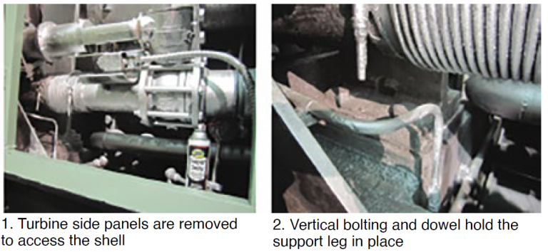
- Remove the side panels adjacent to the turbine shell (Fig 1), taking note of the two shell supports, bolting, and dowels. Each support foot has four vertical bolts and one dowel (Fig 2).
-
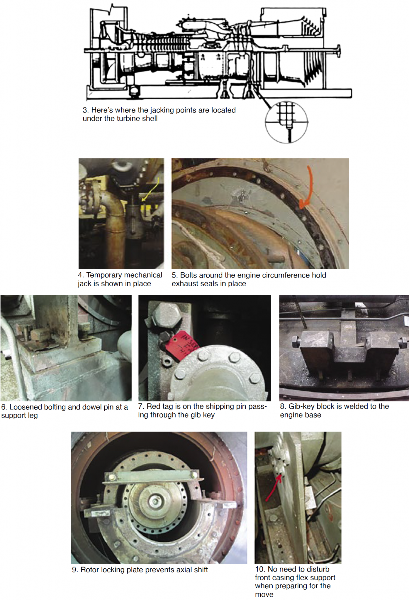
- Loosen the bolts for the two support legs shown in Figs 3 and 4 and install mechanical jacks temporarily at each of the two vertical-joint locations. Next, jack up the shell about 15 mils so a shipping pin can be installed in the lower centerline gib key. Shell lifted, tap loose the shims under the support feet, which may be rusted in place. Note that the turbine must “ride” on a shipping pin in case it is “humped” during transport. This can happen when the machine is lifted by crane or transported by truck or train. Damage could occur to the compressor blades and bearings if the unit is not prepared properly.
- Bolts for the exhaust seal should be loosened, otherwise they may “snap” when the shell is jacked up. The bolts may be rusted, so be prepared to replace them after tapping the holes (Fig 5).
-
- Notice the loosened fasteners and elevated dowel pin between the bolts at the left in Fig 6. The dowel remains in place, shims tapped loose, and support legs are not supporting any turbine weight. Fig 7 shows the pin installed to support the turbine shell during shipping to prevent “humping” of the shell. Red tag is to remind personnel that the dowel should be removed after jacking at the new location. Then the legs can be bolted down to support the shell.
- The horizontal gib key bolts in Fig 8 can remain in place on each side as long as a 25-mil feeler gage can be slipped in to assure the shell (not shown) is not “pinched.” This will maintain the horizontal centerline and shell position. Once they are installed, the mechanical jacks supporting the casing can be removed.
- Front flex-plate bolting need not be disturbed.
- The rotor must be pushed axially against the active thrust bearing (located internally on the opposite end at the No. 1 turbine bearing) to keep the rotor secure during shipment. The axial internal clearance between thrust bearings is about 16 to 19 mils. Use a dial indicator (not shown) to “thrust” the rotor backwards against the active thrust bearing (Fig 9).
- There’s no need to disturb the front compressor flex support when preparing for the move (Fig 10).