
Indiscriminate cost-cutting and/or inattention to detail during equipment manufacture, installation, operation, and/or maintenance are conducive to forced outages and unbudgeted expenses. Generally speaking, unrealistic expectations are to blame, not the individuals charged with doing their jobs faster and at lower cost.
That’s simply the way it is in today’s competitive generation business. How many times have you seen contracts let on the basis of merit rather than cost? Asset and plant managers take the rap when availability and generating capability go south, so it’s in their best interest to share information on emerging issues. User groups are critical to this timely communication. Why should multiple plants be forced out of service for the same reason?
Manufacturers and services providers have a role to play as well, by keeping the industry and their customers informed about what is not performing as planned and how to correct the underlying issues. A case in point is the generator failure described by a user at the 2013 meeting of the Combined Cycle Users Group (CCUG).
The idea that a failure of this magnitude would occur in a generator less than a year after COD caught CCUG attendees by surprise, judging from facial expressions. It’s important to note that this was not a “one-off” failure. The other two generators coupled to gas turbines at this 3 x 1 combined cycle also were on the verge of failure. However, their repairs were relatively straightforward because the problem was identified before serious damage was done.
An objective of the presentation was to encourage owner/operators to pay close attention to OEM advisories, inspect their equipment accordingly, and take corrective action as necessary. The editors considered it unusual for a large generator made by one of the world’s leading manufacturers of these machines to fail in the manner described—especially so because no one else in the meeting room seemed aware of the incident or its cause.
The following report, compiled from non-OEM industry sources, attempts to explain what likely happened and why. Your thoughts on the subject are welcome and will be held in confidence; write bob@ccj-online.com. Alternatively, you can reach out to industry colleagues by communicating via the CCUG users-only forum hosted at http://ccug.users-groups.com.
The downside of cost-cutting. Over the last three decades or so, electric power producers have put increasing pressure on generator manufacturers to reduce the cost of their machines. Particular focus has been on indirectly cooled generators common in combined-cycle plants. A result of cost-cutting initiatives is a trend toward generator designs with increased reliability concerns. Examples include widespread use of the global vacuum pressure impregnation system for stator windings, generators built without isolation between core and frame, and an increase in stator-winding vibration issues attributed to high electromagnetic force (EMF).
Cost pressures also have resulted in numerous, more subtle modifications in construction that may show up as problems in unpredictable formats. An example is the “dry-tie” issue associated with some large indirectly cooled generators built by GE since about year 2000 and described in the article referenced above. The term “dry ties” commonly refers to the use of banding tapes to tie endwindings and connection rings.
Stator-winding vibration, it seems, always has been a leading cause of generator problems. Historically, endwindings were tied with cotton cord, then with glass cord, and then with resin-impregnated materials. This evolution occurred as EMF increased in the endwindings and connection rings.
The resin-impregnated tape commonly used on today’s generators is a dry-tie material. Important variables enter into the tie process when using this material, including these:
-
- The tape is inherently non-lubricating, negatively affecting the ability to tighten the tie.
- The tape manufacturer may, without notice, change the amount of resin within the tape, or make subtle changes to the resin, thereby affecting its bonding and curing properties.
Banding tapes ordinarily are used to make high-strength insulated bands—such as those securing the armature windings on relatively low-speed rotating machines. In manufacturing these bands, the tape is machine-applied with controlled and substantial tape tension. The tape may be heated as it is applied. Significant consolidated cross-sections are built up which make the need for high resin content unnecessary. Plus, resin with high bonding strength is not necessarily required in these applications.
By contrast, making a reliable structural tie with such dry tapes introduces important inherent concerns, including the following:
-
- Obtaining a consistently tight tie using manual tensioning of a cold, non-lubricating tape.
- Assuring an adequate amount of resin required to obtain tie integration and structure component bonding.
- Assuring that the resin has consistent properties for obtaining high-bond-strength capability.
Generator endwinding support systems designed by GE over the last half century are considered “highly reliable” by at least some sources. This performance is attributed, in part, to a design philosophy which as incorporated a “wet tie.” In making a wet tie, many strands of glass roving (fibers) are drawn though a liquid resin as the tie is made.
Wet ties largely eliminate the issues associated with dry ties. They allow the generator manufacturer to assure the purchaser that (1) the resin has a high bonding strength, (2) sufficient resin is applied with the tie to assure a high-contact bonding area, and (3) the tie is made extremely tight by use of tightening leverage and by taking advantage of the inherent lubricating characteristic of a wet resin.
But in making the wet tie, shop personnel are handling a liquid resin in awkward positions involving a large amount of resin contact with hands and arms. Thus, making the wet tie is an uncomfortable and somewhat tedious process; there is considerable incentive to use an alternative process. The dry-tie material is one possible solution, but its application has led to reliability concerns on some GE generators.
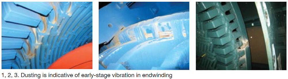
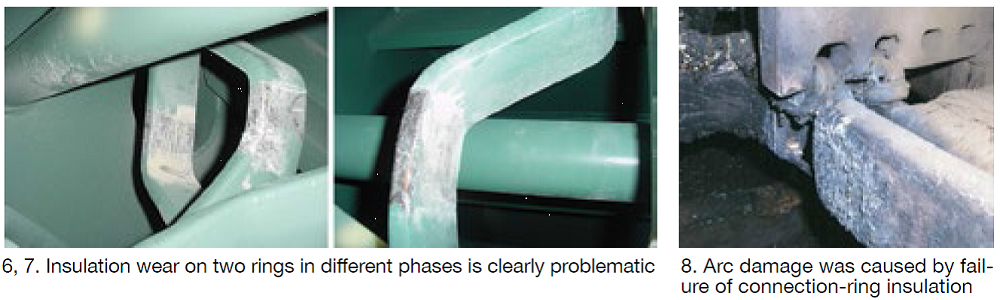
Gallery. Figs 1, 2, and 3 show dusting as evidence of early-stage vibration in an endwinding; Figs 4 and 5 reflect vibration of connection rings. Early-stage dry-tie vibration illustrated in these five photos is relatively simple to repair—that is, to remove the dry ties and replace them with wet ties as recommended by the OEM. Even where insulation wear is significant (Figs 6 and 7), depending on depth and location, it may be possible to repair and retie. An alternative is a stator rewind.
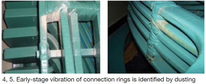
Fig 8 shows a failure location on connection rings. It illustrates the amount of physical damage that can be caused by a failure arc, which persists for several seconds after the breaker trips as field current decays. The photo also shows the relatively weak integration of the tie between ring and support: The ring is connected to the support only at an edge of the ring rather than on a wide face. If the tie and bond are not exceptionally strong, the bond will fail and vibrations and wear can begin.
For the support in Fig 9, note that the ring is contained on the faces but it does not fill the opening provided. Thus the ring is retained only by bonding of the faces and if that bond is broken by differential-expansion forces of cyclic loading, the ring will be free to vibrate.
Some configurations of connection-ring blocking can leave the blocks poorly integrated with the ties and rings. In such cases, the blocks themselves may disbond from the rings and ties. The loose block, or blocks, then can vibrate in a contained space and wear completely through the insulation of both adjacent connection rings. Since adjacent rings likely will be in different electrical phases, this condition is an invitation to electrical flashover and massive arc damage.
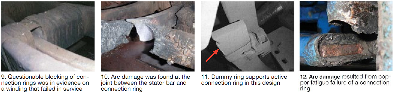
The damage in Fig 10 probably resulted from the arc of a phase-to-phase short circuit between two locations of bared conductor caused by vibration. In the event of a line-to-line failure, the minimum repair likely would involve full stator and field rewinds and extensive core, frame, and cooler cleaning. In a worst case, stator replacement could be required.
A few designs include a dummy ring in parallel to the active connection rings (Fig 11). These generators appear particularly vulnerable to vibration and wear. As shown, the ties are not doing a good job of joining the dummy ring to the support. Keep in mind that the dummy ring is made of a composite material having a significantly different expansion coefficient than copper. During cool-down from bake, and with cyclic loading, the dummy ring tends to disbond and become free to vibrate, shift position, wear the ties, and contact and damage connection-ring insulation. Early failure of the winding may result.
Typically, when dry-tied windings experience severe damage or failure, the cause is from insulation wear as seen in Figs 1-7. However, there is also the possibility that debonding of ties and blocking can result in increased levels of component mobility and/or vibration natural frequencies drifting into resonant situations. These changes can result in much faster insulation wear, but they may also result in high-cycle fatigue and fracture of the copper conductor (Fig 12). Each of these conditions, insulation wear and copper fatigue, is extremely dangerous to winding integrity.
Fleet. There have been about 450 generators of the 7FH2 type manufactured between 2000 and 2011. Of those inspected, roughly 15% reportedly exhibited dusting; four with the dummy-ring design showed wear. Recall that the dust generated will appear as a blackish “grease” if the unit is oily. A significant number of 324, 330H, and 390H generators also have been inspected. A few were found with problems ranging from light dusting to serious insulation wear and exposure of copper. These problems focus on the connection rings and the OEM has recommended urgent action on inspecting these specific classes of generators in its advisories. A few that the editors were made aware of include these:
-
- Technical Information Letter (TIL) 1764, “324 and 330H Consolidated Dry-Tie Connection Ring Insulation Abrasion,” February 2011.
- TIL 1792, “7FH2/7FH2B Consolidated Dry-Tie Connection-Ring Insulation Abrasion,” May 2011.
- Electronic Technical Correspondence (ETC) 129, “Generator Stator Endwinding Dusting,” September 2004.
It is difficult for the OEM, or for the owner, to predict which specific generators in the 7FH2, 324, 330H, and 390H lines may be experiencing difficulty. Reason is that there are numerous, sometimes unknown, variables that can contribute to vibration problems. These variables include the following:
-
- Electromagnetic forces differ from design-to-design and kVA rating within that design category. These forces have a strong correlation to mechanical duties.
- Variations in winding design, particularly for the connection-ring support structures.
- Tie-material properties are not accurately known to the OEM and may vary somewhat randomly from generator to generator.
- Workmanship may vary from generator to generator, and from bar to bar within a given machine. Such variation depends on the skill and motivation of the individuals performing the work. Fig 1 illustrates this: Some bars are vibrating, others are not.
- Deterioration depends on kVA output and the amount of load cycling, and this information is not readily available to the OEM.
It is clear that among individual generators of the classes noted above, there are unknown interactions of design, materials, workmanship, EMF, and operating duty. In general, then, it is unlikely that one can predict with accuracy which generators are vulnerable to damaging wear. However, there are exceptions that are said to have been made clear to the owners by the OEM. One example is the dummy-ring class of generators.
The OEM has issued recommendations related to inspection, stocking of materials, and the repair of any problems relating to the dry tie that are found. Repair is relatively simple if issues are identified before failure occurs. After a failure involving line-to-line flashover, repair can be very costly and include a long outage.
The bottom line: Unless your generators already have been inspected and found vibration-free, consider at least a cursory inspection of each machine as soon as possible. At a minimum, the initial inspection should focus on the connection end; it involves only removal of the upper outer and inner end shields, and the manhole covers of the non-connection end. But in every case, advice of the OEM should be considered carefully and this advice factored into your investigation and maintenance plans. CCJ