By Lee S Langston, professor emeritus, UConn
Axial-flow compressors are used in the majority of large gas turbines, both in powerplants and aircraft jet engines. Over the last 75 years these compressors have been improved continuously, today achieving component efficiencies of more than 90%. However, no matter how advanced, they must be carefully controlled in their operation to avoid the power-robbing effects of stall and the convulsive effects of complete flow reversal, brought about by surge.
Although modern design and fuel control systems are capable of keeping a gas turbine in electric generation service away from operating conditions conducive to stall and surge, it is important to know something about each condition. With this as an enjoinder, let’s look at how an axial compressor operates.
Axial compressor basics
To efficiently compress a gas over a range of operating conditions is not an easy task. About 50% to 70% of the output of the turbine component in a gas turbine is used to drive its compressor. Contrast that to a steam plant where only about 1% of the turbine output is used to power feedwater pumps to resupply incompressible water to the boiler.
Axial compressors get their name because gas-path air flows in more or less a straight line in an axial direction, parallel to the gas turbine’s axis of rotation. The compressor is assembled in stages, each stage comprised of a ring of moving rotor blades (or blades), mounted on a rotating disc or drum, and a downstream ring of case-mounted stationary stator blades (or stators).
Blades do work on the gas-path air flow, increasing its static and total pressure, and kinetic energy. Stators remove blade-induced swirl velocity, thereby decreasing kinetic energy, serving to also increase static pressure and align flow for blades in the next stage.
Compressor blades and stators then operate on gas-path flow to produce what aerodynamicists term an adverse pressure gradient in the flow direction—that is, from low to high static pressure. This is analogous to pushing water up an inclined channel, with many small, rapid brush strokes. If the incline (akin to the compressor pressure ratio) is too steep, the water runs backward, down the slope.
By contrast, gas-path flow in a turbine operates in a decreasing static pressure field in the axial direction. This is termed a favorable pressure gradient: think of water being brush-stroked down a declined channel.
Multistage axial compressors: The basics
The gas path in a typical single-spool six-stage axial compressor is shown in Fig 1. Air enters IGVs (inlet guide vanes, which are not present on all gas turbines) and passes through each of the stages, on its way to the combustor section. Each stage increases both the gas-path static and total pressure.
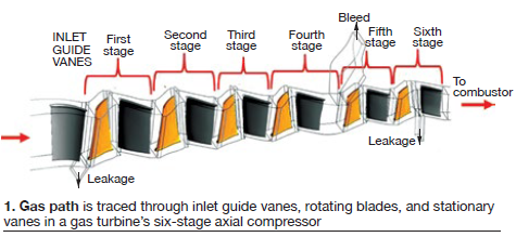
Typically, each compressor stage in an industrial gas turbine (IGT) operates in a pressure-ratio range of more than 1.0:1 up to about l.4:1. To calculate a machine’s compression ratio, simply multiply the pressure ratios for each stage. Example: Referring to Fig 1 and assuming each stage has a pressure ratio of 1.2:1, the compression ratio would be 1.2 to the nth power, where “n” is the number of stages—six in this case. The result: 2.99:1.
The benefit of a high compression ratio is top performance. Bear in mind that the thermal efficiency of a gas turbine increases as pressure ratio is increased. To illustrate: In the early 1950s, an axial compressor with 15 stages might have had an overall pressure ratio of 4:1. Today, GE’s most advanced F-class gas turbine, the 7FA.05 gas turbine (231 MW), has a 14-stage compressor with an overall pressure ratio of 18.4:1.
This represents a reduction of one stage and an almost five-fold increase in compression ratio in seven decades of compressor design progress. Pressure ratios of the latest frame engines go as high as 30:1; those for aeroderivative machines, up to about 40:1. Such compression ratios translate to gas-turbine thermal efficiencies in the 35% to 45% range. The earliest IGT (1939) had an efficiency of 18%.
As Fig 1 shows, the compressor gas path narrows in going from the first to the sixth stage. Given that the average gas-path velocity in an axial direction is relatively constant for a GT compressor, as pressure and air density increase in the direction of flow the blades and stators become shorter. Tip-clearance issues can occur in high-pressure stages because the allowable clearances are more significant for shorter airfoils.
Compressor stall
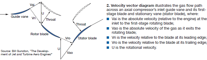
An engineer may begin the design of an axial compressor using velocity vector diagrams for just the IGV and the first compressor stage (Fig 2). They will identify the necessary air inlet flow angles for blades and stators to meet the desired operating conditions.
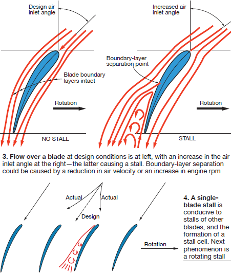
The resultant air-flow streamlines around a compressor blade are shown in Fig 3 (left) for the design flow angle. (The sketch for a stator would be similar, but without rotation.) Going from low pressure at the blade’s leading edge to a higher pressure at its trailing edge, the streamlines closely follow the blade’s suction and pressure surfaces.
The flow around the blade is controlled by its boundary layer. This is a very thin, almost immeasurable layer of air on the blade surface, within which the viscous frictional effects are concentrated. The velocity changes in the boundary layer from that of the streamlines just outside it to zero (relative to the blade surface) at the blade surface.
The existence of a boundary layer was introduced by the German engineer Ludwig Prandtl in 1904—an appropriate time to profoundly influence the design of aircraft as well as turbomachinery, in the last century and today.
Boundary layers are very sensitive to the conditions brought about by adverse pressure gradients, which is what a compressor produces. Thus the designer is careful to insure that boundary-layer separation does not take place at design air inlet angles.
When air inlet angles (measured in the axial direction) are increased, separation of the blade boundary layers can occur, as shown by the streamlines around the blade at the right in Fig 3. Here the streamlines on the suction side do not follow the blade surface aft of the boundary-layer separation point. This compressor blade is stalled.
Stall immediately increases stage aerodynamic loss: The blade lift goes down and the desired pressure increase is not achieved. The larger air inlet angle precipitating the stall could have been caused by a drop in air velocity as might occur from a sudden downstream backpressure event—for example, one resulting from a blockage in the combustor or turbine—or an upstream flow disturbance. Other separation causes could be blade surface roughness or excessive tip leakage.
When one blade goes into stall, it can cause an upstream blockage which diverts approaching stage flow (Fig 4). This is conducive to increases in the air flow angles for adjacent blade passages—in a direction opposite to rotation. If flow angles are large enough, these blades also will stall, forming a so-called stall cell. If the stall cell itself moves, it becomes a rotating stall, which spins opposite to compressor rotation, at about half the shaft speed. Needless to say, rotating stalls can greatly reduce blade life, because of the increased stress and vibration they cause.
Compressor surge
Rotating stall can morph into the extreme case of a compressor performance failure called surge.
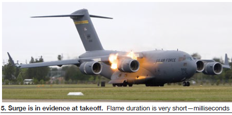
In the words of compressor expert Ivor Day, stall is a disturbance of compressor flow in the tangential direction, while surge is a disturbance in the axial direction. During stalled operation, the average air flow through the compressor is steady, but during surge, the flow rate will rapidly (milliseconds, msec) pulse—sometimes so violently that reverse flow is induced, often accompanied by a loud “bang.”
In extreme cases, a sudden combustor-induced flame may shoot out the back end of the machine (Fig 5) and possibly out of the compressor inlet as well. Thus it’s important to avoid surge.
Preventing stall, surge
As explained earlier, the onset of stall (and surge) can be traced back to the behavior of the boundary layer on compressor blades and stators. Since this is the result of the basic physics of boundary layers, no “cure” has been found to eliminate stall.
When an OEM designs a new compressor it usually is tested to see when it will stall, using hindsight to determine what conditions to avoid. Then engine control systems, such as Fadec (Full-Authority Digital Electric Control), are programmed to keep the operating point of the compressor well away from the so-called stall or surge lines. Variable-pitch stators (to control flow angles), compressor bleeds, casing treatments, and tip clearance controls all are used to avoid stall conditions.
The study of stall and surge is a very active area of R&D in the worldwide gas-turbine community. According to Robert Mazzawy of Trebor Systems LLC, who in 1980 was one of the first to report on surge-induced structural loads, researchers have found that subtle modal waves are precursors to the rotating stall that precipitates surge. The hope is that detection of such waves will allow the Fadec to prevent stall and surge.
The fundamental problem is the nominal time period required for the actuation of a variable stator or a bleed is about 200 msec. This contrasts with the time period for the development of rotating stall and surge which is on the order of several rotor revolutions. One rotor revolution for an aircraft gas turbine typically is about 5 msec, while for a large IGT might it be as long as 20 msec. The difficulty of having the Fadec sense a precursor and take the necessary activation to prevent stall and surge becomes obvious when considering the disparity of these time intervals.
Despite the difficulties of sensing modal-wave precursors, there have been some successes in utilizing a Fadec to sense an impending stall/surge in sufficient time to either prevent its occurrence or limit repetitive surges. One example has been with twin-spool aircraft gas turbines where the initial stall originates in the fan stream from FOD damage or excessive clearance or flow distortion from nacelle inlet separation.
Here’s what likely would happen: Fan stall leads to loss of flow capacity which causes the low-rotor speed to increase above the normal level for the engine power setting. A higher-than-normal low-spool rotor rpm coupled with a normal high-spool rotor speed elevates the low-pressure compressor (booster) operating line to its stall line, resulting in rotating stall and eventual surge. The time required for the low spool to increase its rpm is now sufficiently long for the Fadec to sense the unusual relationship between low- and high-spool speeds and be able to activate a bleed to prevent the occurrence of surge.
Another example: Aircraft gas turbines operating in severe rain or hail storms where extra fuel is required to process and evaporate the water being swallowed by the engine. Here again, the Fadec can sense the abnormal amount of fuel flow for the power setting and take preventive action to prevent any engine instability.
Neither of these examples would be applicable to IGTs but they serve to illustrate that given enough time for the Fadec to sense an unusual mode of operation, it is possible to prevent stall/surge. CCJ