


Input from monitoring, inspections, tests critical for maintenance planning
Clyde V Maughan, Maughan Generator Consultants
There is increasing pressure to extend inspection/maintenance intervals for gas and steam turbines and their generators. One important approach to cycle extension has been predictive maintenance. However, predicting the maintenance requirements for a generator is a difficult task, because relatively little information on its health can be accessed by monitoring an operating unit.
Identified below are the three primary tools used to assess generator condition; each has important weaknesses.
- Monitoring. Several of the most common deterioration mechanisms are not monitored at all.
- Inspection has several limitations, including: (1) the need to disassemble components, (2) many areas are inaccessible for inspection even with state-of-the-art diagnostic equipment, (3) the quality of the assessment is highly dependent on the technician’s skills.
- Tests. Each of the many tests available to a generator owner/operator has one or more limitations. Examples: (1) cannot identify local areas of weakness without risk of insulation breakdown, (2) provides average results only, (3) insensitivity to vital deterioration mechanisms, (4) requires specialized equipment, (5) hazardous to personnel.
Monitoring
Generator stators and fields historically have been monitored by relatively unsophisticated instrumentation. These standard devices, even when supplemented by state-of-the-art instrumentation, do not detect many common modes of failure, including the following:
- Stator-bar vibration without partial discharge or vibration sparking.
- Stator-bar strand-header water leaks.
- Developing cracks in stator-bar connections.
- Field coil/turn distortion.
- Forging cracks.
Unfortunately, equipment capable of detecting these problems does not appear forthcoming. Thus, predictive maintenance will remain based on financial considerations, rather than on the actual condition of the generator. However, if inspection and test are conducted judiciously, a good assessment of generator condition generally can be accomplished.
Equipment
 The instrument measures actual vibration levels and tracks changes in vibration magnitude over time. This information is valuable for determining when an outage should be scheduled. Preliminary data suggest that 3 mils may be the upper limit for a long-term safe vibration level.Stator end-winding vibration is one of the most common deterioration mechanisms affecting large generators. Machines suspected of having excessive end-winding vibration can be monitored with detectors relatively new to the market (Fig 1). These devices have no electrical conductors and can be safely placed on the high voltages existing on stator-bar surfaces.
Partial discharge (PD) exists on virtually all stator windings. While it tends to be a very slow deterioration mechanism on mica insulation, PD is a good telltale for several common deterioration modes—including stator-bar vibration in the slot and some forms of contamination. With good PD sensors and monitors, useful data can be captured. However, interpreting the significance of those data and eliminating “noise” continue to be the most difficult aspects of PD testing (Fig 2).
Testing-company approaches to PD data analysis are not standardized. One major vendor has relatively simple procedures and instrumentation, and a very large database. This allows a generator owner’s engineering personnel to collect and analyze their own data with nominal training.
Other testing vendors prefer to collect the data with their own personnel and instrumentation, and then forward the results to a central engineering group for analysis. Both approaches have given good results in monitoring generator performance.
In several cases, units have been removed from service to investigate high readings, thereby allowing the correction of significant problems before major damage occurred. While some judgment of winding quality is made on absolute readings, all vendors rely heavily on trending of readings over time for a given generator. A winding trending rapidly upward is monitored closely and, depending on readings, may be disassembled for inspection.
Stator-winding RTDs and TCs. Many owners want to operate their generators based on winding temperatures. Two thoughts here: (1) The information obtained from a winding-slot RTD is related only peripherally to actual copper temperature; (2) temperature is only a secondary cause of generator deterioration.
Regarding the first point, the RTD reads a “composite” temperature of cooling gas, core iron, and winding copper through an insulating blanket (the groundwall insulation). RTDs and TCs positioned to read the temperature of the cooling medium discharged from a direct-cooled bar offer a better measure of temperature, but give only indirect guidance as to copper hot-spot temperature.
Slot RTDs offer no useful information regarding insulation deterioration on water-cooled windings. But they can provide some guidance relative to buildup of internal contaminants (and partial plugging) within the hollow strands.
Generator condition (core) monitor. This equipment monitors a generator for any source of excess temperature—including several important deterioration mechanisms related to localized problems (Fig 3). These include core lamination shorts, failing electrical connections, and plugged ventilation circuits.
With the addition of temperature-sensitive paints, the core monitor can give a general indication as to where a problem may be occurring. Although monitors made prior to about 1990 were prone to false-positive alarms, later models are more reliable and their alarms should be investigated.
Field flux probe. Equipment for detecting field-turn shorts has been available for 60 years, but it has gained general acceptance and use only in the last 25. The flux probe is a simple device (Fig 4, white arrow), but the test takes time to do correctly.
Testing requires plant operators to vary generator load over a specific range of kilowatts and kiloVArs. The flux probe is inexpensive and accurately identifies the number of turn shorts in each coil; it has little exposure to error or ambiguous readings. Every generator of importance should have a flux probe installed on its stator.
 Field vibration. One of the more common problems associated with fields is that of “thermal vibration vectors”—that is, vibration related to the magnitude of the field current.
To assess the impact of a thermal vector on a field, vibration magnitude and angle must be measured. Having both it is relatively easy to determine the length and angle of the thermal vector. With this information, rational determination of corrections can be made, and some information as to root cause of the vibration usually can be obtained.
Field ground detection. This is standard equipment on generators and should be monitored continuously. Because either single or double field-ground conditions can be hazardous to personnel and equipment, the unit should be brought offline immediately in the event of a confirmed field-ground alarm. For a field known to be in poor condition, an immediate trip may be advisable.
The field-ground device offers no information as to where the ground might be within the field, or external to the field. This can be determined with two simple tests:
- Location of ground within the winding can be obtained by flowing a relatively small current through the winding and measuring voltage to ground from each end of the winding.
- The axial location in the field body can be found by flowing a larger current from end-to-end on the field forging, and accurately measuring the point at which voltage from the winding to the forging passes through zero.
Inspection
Inspection probably is the most powerful generator condition-assessment tool, when it is done properly. The process has several limitations, including these: many areas cannot be seen, even with the best tools (robots included); inspection can be time-consuming; results are qualitative and highly technician-dependent.
Inspection teams rely on the fact that many of the prevalent deterioration mechanisms leave tell-tale signs of trouble, including: dust, dirt, grease, fretting discoloration, displacement, cracks, foreign objects, deformation, and distortion. But evidence may be subtle and limited, particularly in the early stages.
Because inspection is inherently difficult, and judgment often is required to rate the significance of the evidence, the work must be performed by a qualified individual or team for the results to be complete and reliable. Training and experience are important, and on new or more complicated phenomena, knowledge of generator design may be indispensable.
Accessibility
Field in place. Fully assembled generators typically (1) allow little access for inspection and (2) provide little information as to generator condition (Fig 5). Some machines, particularly air-cooled units, have ports that allow good access for inspecting the outside diameter (OD) of stator endwindings and the connection rings—an important deterioration area.
Removal of coolers and the inner and outer top-half end shields (bearing brackets) allow use of mirrors, borescopes, and miniature video cameras to possibly access retaining rings, field end wedges, core end iron, and stator end wedges.
Robotic equipment can traverse the entire length and circumference of the air gap in most generators—even ones with gap baffles (Fig 6). These robots typically carry a camera and wedge-tapper device.
They facilitate assessment of many vital generator parts and deterioration conditions, including: stator bar vibration, stator and field wedges, stator wedge tightness, stator core, air-gap baffles, core ventilation ducts, and radial-spring ripple height on some wedge designs.
 When making a go/no-go decision on robotic inspection, keep in mind that it is both expensive to perform and likely to uncover a problem that would require field removal anyway.
Field removed A “complete” stator and field inspection requires field removal. Direct access is provided to surfaces such as stator end windings, vent ducts via borescope or very small flashlight, and under retaining rings with borescope and mirrors. Examination of stator bars is improved, allowing more accurate evaluation of the critical mechanisms of bar vibration and PD.
However, even with the field removed, there remain many inaccessible, but important, inspection locations, including: much of the field winding under the wedges, sides of the stator bars in the slots, core iron beyond the inner surfaces, most of the field winding under retaining rings, internals of the stator-bar insulation, etc.
Stator winding
The slot portion of the stator winding is critical, but the areas of greatest interest are behind the wedges and iron core—and inaccessible. Direct view of the bar surfaces is limited and the effects of PD and/or vibration sparking are not possible to determine on many windings. Removal of selected wedges may allow access to important conditions (Fig 7).
On generators with radial core ventilation ducts, borescopes can give good access to the sides of the bars at the ducts. But the distortion inherent in borescope viewing may make difficult the interpretation of what’s being seen (Fig 8). Once again, the technician’s skill and experience are critical to inspection success.
It’s important to manage your expectations: Inspection of the slot portion of a winding often leaves one with an uncertain feeling as to the quality of the winding.
Stator end windings are much more accessible than the slots, and failing connections can be observed (Fig 9). Dust or grease deposits may indicate vibration or foreign objects, but the extent of damage, if any, may be difficult to assess (Fig 10).
PD activity can cause several conditions that are detectable by inspection (Fig 11). The numerous indications on the endwindings may add to the uncertain feelings resulting from inspection of the slot portion of the winding.
Mechanical damage. Where a generator has been subjected to short-circuit or mis-synchronizing incidents, the winding will have experienced high mechanical forces. The tiny cracks that may be seen in an endwinding after such an incident are easy to overlook (Fig 12). Observed cracks may simply have resulted from normal differential expansions within the endwinding (Fig 13). Visual inspection alone might not be sufficient to assess the extent of winding damage.
Stator core and frame
General deficiencies. Most core deficiencies can be observed from the core’s inner surfaces, but the defects sometimes can be so small as to be virtually invisible to all but the skilled inspector conducting a close examination.
If heavy contamination is found on the core ID and in ventilation ducts, inspectors should determine the source and nature of the contamination to facilitate corrective action. Careful inspection, combined—where appropriate—with core flux tests should give a good assessment of core condition.
Core mechanical damage, looseness. Mechanical damage covers a broad spectrum. Minor faults typically appear as small, local areas of solid-metal surface or of scorched lamination paint (Fig 14). They are easily overlooked if inspection is not thorough.
By contrast, severe mechanical damage is easy to spot. It may be caused by core looseness, foreign objects, improper wedging, or careless field assembly and removal. Looseness usually occurs at the inside diameter near the ends of the core, where it is easy to identify (Fig 15). Look for dust generation, punching and spacer movement, or small pieces of punchings that have cracked off.
 But while you have good access to core surfaces, keep in mind that there may be issues deep inside the core. This means it’s not possible, ordinarily, to accurately assess core condition by visual inspection alone.
Field inspection
Field windings are difficult to inspect without some disassembly, making it challenging to assess the actual condition of windings in most machines. Numerous problems may be occurring, including: coil displacements or deformation (Fig 16), turn displacements, contamination buildup, turn and slot insulation displacement and cracks, shifted or missing blocking and baffling, and arcing or burning between conductors (coils, turns, leads) and ground.
However, access is improved dramatically by removal of the retaining rings. Inspection after this step can be quite complete. Also, keep in mind that on direct ventilated fields, inspection can be made through the ventilation holes in the wedges on the body portion of the field (Fig 17).
Collector/brushholder rigging. Ongoing inspection and maintenance are vital on these components, which probably are the source of more forced outages than any other generator component. If failure occurs, the condition may be correctable with modest effort, but it also may result in an outage of several month’s duration.
To illustrate: The arc damage in Fig 18 may be repairable by grinding the affected rings and replacing the burned brush-holder components; this could take anywhere from several days to a week.
In Fig 19, rotating components appear close to failure. Situations such as this are conducive to severe plant damage and to injury or death of personnel. At a minimum, repairs will require replacement of the entire collector assembly and brushholder rigging. But if the field forging also is burned, costly and time-consuming forging repair may be required. Outage time could be weeks or months.
Tests
Each of the many tests that can be conducted to evaluate a generator’s condition has one or more of these limitations:
- Cannot find local discrete weak areas without risk of insulation breakdown.
- Gives average results only.
- Insensitive to vital deterioration mechanisms.
- Requires specialized equipment.
- Personnel hazard.
A variety of tests is used in offline evaluation of generators. Most are common to all types of machines, but some are used on specific classes of generators. The majority has been used since the infancy of power generation, but a few are of more recent development. Most of the tests are benign and will not harm the component under test. The primary exception: over-voltage testing.
Precise evaluation of a generator’s condition is difficult even under the best conditions. But if the full battery of tests described here is used, important assessment of equipment condition can be obtained.
Special considerations. Because the over-voltage test is so valuable an evaluation tool for stator windings, and because owners often are reluctant to allow its use, the merits of this test are worth reviewing.
Most plant supervisory personnel are aware that stator insulation systems deteriorate at a modest rate, and unless subjected to poor O&M practices or localized distress; they should serve for 30 to 40 years—or longer. They also know that during every type of over-voltage test, there is the possibility of failure to ground.
But many plant decision-makers are unaware that (1) failure almost never occurs during a properly conducted over-voltage test unless severe stator-winding degradation already has taken place, and (2) a good stator winding insulation system is not measurably degraded during the application of over-voltage.
There are no industry standards specifically addressing maintenance high-potential (hipot) testing of stator windings. OEMs often recommend an in-service test value of 1.5E (E is the line-to-line voltage), although some are reluctant to over-voltage test at all.
The recommendation to test is based on the knowledge that bars failing the test invariably show severe insulation degradation attributed to operation. Note that new insulation will hold roughly four times the highest maintenance over-voltage values recommended.
There always is the possibility of winding failure during an over-voltage test. When this occurs, it often is not possible to make a local repair of the failed area. Thus, unless previous preparations have been made (spare parts, repair personnel, outage time scheduled), a major outage extension may occur.
Hipot testing is a particularly important evaluation tool for a stator with general and serious deterioration. This is true because the first failure is likely to be at a location in the winding near the line-voltage end—but at line-to-neutral voltage. The first failure will place the line end of the other two phases near line-to-line voltage to ground and thus overstress weak bars in these locations.
Should a second failure occur on the winding, extremely high current will flow through the faults. The resultant burning will be severe, and the current cannot be interrupted until the field voltage has decayed. The time constant for a typical field is about 5 seconds. Thus, it may take 5 to 10 seconds for the field current to decay to a level that will extinguish the stator winding arc.
Double-winding failures have occurred on a significant percentage of stator windings in generally poor condition that have failed to ground in service; each case resulted in full stator and field rewinds, extensive cleaning, and, oftentimes, partial core restacking.
In reaching the basic decision relative to performance of stator hipot tests, the owner is faced with divergent and conflicting alternatives: Perform a suitability-for-service high-potential test and risk stator-winding failure, or omit the hipot test and accept increased risk of service failure, forced outage, possible extensive machine damage, and a long unplanned outage. In the final analysis, depending on the importance of a particular machine to the system, and other business and economic factors, judgment must be made between these two options.
Equipment selection. The most effective electrical-test evaluation tool for the quality of a stator winding is the hipot test. The choice of test-voltage source is of secondary importance; all three commonly used systems are effective: power frequency ac, 0.1Hz ac, and dc.
The dc value accepted by the industry is 1.7 times the 60-Hz rms value. (Actually, there is not a simple, direct relationship between the two types of voltage. Laboratory comparison tests have shown values as low as 1.414 and as high as 4.0. The 1.7 multiplier is an acceptable compromise.)
Caution: Maintenance over-voltage testing generally is not recommended for fields. The 500-V megohmmeter provides sufficient voltage for testing the low-voltage field.
PD offline test
Several types of offline tests are used to locate PD sites within a stator winding and to assess its magnitude at each location. They rely on a PD-free source to apply a selected high voltage—generally the line-to-neutral voltage of the stator winding. Thus all portions of the winding are at the test voltage and there are no electromagnetic forces on the bars.
Note that there have been rare cases of winding failure at this relatively low voltage. In every case, the winding was in an extremely advanced state of degradation.
There are limitations in the validity and interpretation of the information acquired during PD offline tests. Trend review and comparison to duplicate windings may be of greater value than analysis of absolute readings. No industry standards exist on data analysis.
Online test sensor. The sensors and analytical instrumentation used for online testing can be used for offline tests as well. The same challenges exist with respect to signal collection and interpretation, except that there are far fewer spurious signals offline.
The following general principles apply to interpretation of results:
- Readings above 5000 pC (picocoulombs) may be indicative of winding deterioration.
- Equal distribution of positive and negative pulses may indicate there are voids within the stator-bar groundwall insulation.
- A preponderance of positive pulses may suggest voids on the outside surface of the insulation.
- Predominance of negative pulses may indicate voids at or near the copper.
Individual bar probes. Both radio-frequency and ultrasonic probes are used (Fig 20). The individual bars are probed in the areas of the endwinding and in that portion of the slot that is accessible safely. Readings are taken of any active site; most useful data are obtained at locations of high PD activity.
Don’t underestimate the considerable personnel safety hazards associated with use of a probe for PD testing. Be sure all personnel are properly equipped and trained before allowing them to participate in this activity.
General stator, field testing
Several other tests also are used to evaluate field and stator insulation systems. The most significant of these are summarized below.
Megohmmeter. The insulation resistance value indicates overall insulation integrity, and may identify a fault that responds to relatively low voltage. But contamination, particularly with a conductive material or in the presence of moisture, may result in a low megohmmeter insulation resistance reading on a very good insulation system.
Polarization index (PI)—the ratio of the 10-min megohmmeter reading to the 1-min reading—is indicative of the extent of dirt and moisture contamination. If the insulation is dry, PI tends to be high—in the range of 1.5 to 4.0. If the insulation is damp—internally or externally—flow of electrical current will be high and predominately resistive; a PI reading of 1.5 to as low as 1.0 can be expected.
Megohmmeter readings vary from machine to machine, or on a given machine over time. Judgment is required to interpret the megohmmeter resistance and PI values, which often dictate maintenance actions—such as winding cleaning and drying.
Power factor and PF tip-up. Power-factor testing is perhaps the most common elevated voltage test performed on stators (often under the name “Doble testing”). While the test itself is quite straight forward, interpretation is not.
It is popularly believed that power factor and tip-up relate closely to winding condition, and often this is not the case. More likely, surface contamination and moisture are responsible for high tip-up values, and perhaps high power-factor values as well. On the other hand, very low values may not be indicative of good insulation system quality.
Power-factor and tip-up tests are useful and worthwhile to perform. But the test results only can be relied on as a guide, rather than as an absolute measure of system condition. High, low, and “optimum” readings can be associated with insulation systems in good and in bad condition.
Stator wedge tightness. Historically, tightness has been checked with a small (2 oz) ball-peen hammer. While inherently subjective, with some experience and training, a competent technician can make an accurate judgment of wedge tightness. More recently, acoustic and mechanical test devices have been developed and are in wide use (Fig 21).
Mechanical testers also are available on robot carriers capable of checking wedge tightness without removing the field. Mechanical testers provide quantitative data that can be monitored over time for trends. However, the validity of these test devices requires that the devices be properly calibrated; otherwise, the device might indicate that a tight wedging system is loose. Test results from a mechanical tester always should be confirmed by hand-tapping a few wedges.
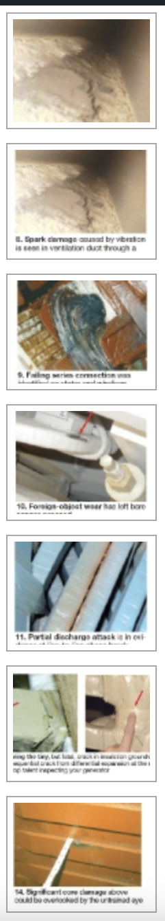
Resonant frequency test. Stator endwinding resonant frequency tests are used to assess resonant frequencies and the looseness of endwindings and connections. “Bump” tests commonly made on new windings are vital for in-service stator endwindings experiencing vibration problems, or ones that have been repaired (Fig 22).
The tests require specialized equipment and trained personnel. Interpretation of results can be challenging. In general, test resonant frequencies should be higher than double power-system frequency by at least 20 Hz—that is, 140 Hz for 60-Hz systems.
Bearing insulation. The condition of bearing and hydrogen-seal insulation must be determined as well. Test voltages will be low; stable resistance values of more than 1 megohm are satisfactory.
Winding-copper resistance (field and stator). Off-spec resistance values are uncommon. But because the changes in resistance values over time are important, they should be recorded regularly.
An out-of-range high reading on the stator may indicate failing connections, a serious condition that requires investigation. The same is true for fields. Low field readings usually are associated with turn shorts. Low stator readings are unlikely. Theoretically, they would indicate shorted turns, but a shorted turn would have failed the winding in service and would not have been found by test.
RTD/TC calibration. It’s important to verify the accuracy of RTD/TCs regularly and to calibrate them as required. The data they provide is critical for trending generator performance over time.
In general, a high in-service reading from a specific temperature device likely reflects an instrumentation problem. But a true out-of-range reading may indicate very serious component distress.
When a generator has been offline for an extended period, a good way to check the accuracy of these devices is to simply compare readings among them. All data should be in a fairly tight band with no significant discontinuities in the pattern.
Stator core tests
Testing of core insulation is essential because inspection alone may not reveal all the issues. Core tests also can help (1) characterize known problems, (2) clear up any doubts regarding inspection findings, and (3) confirm that no damage was done during maintenance work that directly or indirectly involved the core—such as stator rewedging, bar replacement, etc.
These tests are not simple and should be performed by experienced, qualified personnel with top-quality equipment. Two types of tests are used: low- and high-power. Both have significant weaknesses.
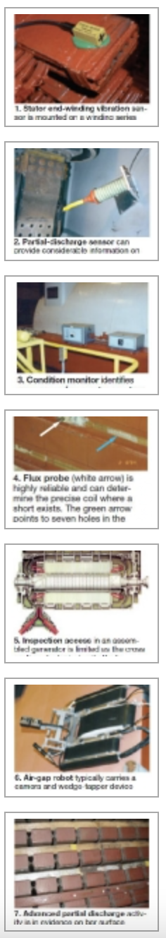
Low-power lamination insulation test. The most common low-flux test today is conducted at about 4% rated flux density using an electromagnetic core imperfection detector—the so-called ElCid test. The advantages of this test are several, including: equipment cost is low, setup is short and simple, quantitative results are obtained, and data generally are repeatable. Additionally, and perhaps most importantly, there is no hazard to the equipment and little personnel safety risk (Fig 23).
As noted above, all tests have their weaknesses. Among ElCid’s disadvantages are its insensitivity to damage deep in the core and the need for special equipment to get accurate readings on the step-iron at the ends of the core. Also important: Correspondence between high ElCid values and core quality may be uncertain.
Overall, ElCid is a valuable test. However, it is not a sufficiently powerful tool on its own to justify restacking of a core—regardless of data quality and the capabilities of those performing the tests. If questionable results are obtained, a high-flux test should be performed.
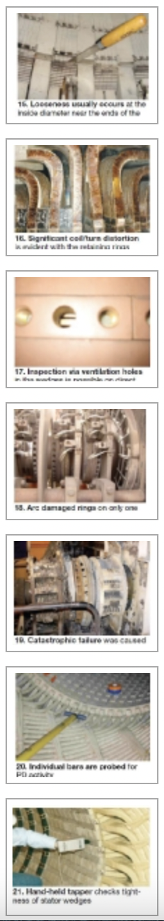
High-power lamination insulation test. Most often called the “ring” or “loop” test, this test is characterized by its time-consuming setup, need for a long length of high-amperage unshielded cable, and costly power source requiring heavy breakers and controls (Fig 24). It also has inherent personnel and equipment safety risks.
Thus the ring test usually is not performed unless inspection and/or a low-power test suggests the core is defective. The bottom line: A well-performed core inspection, combined with unsatisfactory results from a properly conducted high-power test, raises serious concerns about core health and may warrant core iron replacement.
Liquid-cooled winding tests
Liquid-cooled stator windings have thousands of brazes, welds, and other connections where leaks can develop. Several tests can be used to verify the integrity of joints. Rigorously applied, these tests can give high assurance that the system is generally tight.
However, the tiny leaks associated with strand headers may not be found with any of the leak-test methods in use today, and these leaks may wet and irreparably damage the stator-bar groundwall insulation.
Such damage can be identified by methods for detecting wet insulation—including capacitance testing and instrumentation that directly measures the water content of wet insulation. Both methods are subject to error, and a winding should not be condemned without having highly reliable data for decision-making. Before deciding to repair or replace a winding, be sure to take readings with the field removed and to thoroughly inspect areas where wet insulation is suspected.
Field forging tests
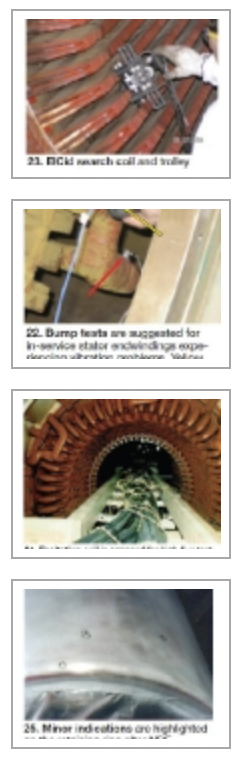
Nondestructive examination (NDE) techniques are used for assessing field forging and retaining-ring forging condition. But careful visual inspection is essential for recording gross evidence of concern, including: visible cracks, fretting, movement on shrink fit, etching, burning, rust (on magnetic rings), and mechanical damage (Fig 25).
The take-away
Accurately predicting the timing and scope of all needed maintenance on an operating generator is not possible with the present state-of-the-art of generator monitoring, inspection, and testing.
However, skillful use of all available knowledge can minimize the maintenance cost required to maintain a high level of reliability. To accomplish this goal, good O&M records are vital, as well as attention to all available information from monitoring, inspection, and testing activities.
Prudent to keep in mind is that even with best-in-class monitoring systems, generators remain with little or no detection capability for several common and serious deterioration and failure mechanisms—such as those identified at the opening of the monitoring section on p 134.
A vital point: While inspection and test of generators is challenging enough a task, correctly diagnosing the root causes of new and more subtle failure mechanisms can be much more difficult. In general, OEM onsite service personnel are trained in inspection, test, and repair of generators; they normally are not trained in diagnostics.
Failure to retain qualified experts for root-cause investigations means quality, timeliness, and cost of repair (as well as equipment reliability) may suffer greatly. Invalid root-cause determinations are believed responsible for annual losses of many tens of millions of dollars industry-wide.
Finally, extension of inspection/maintenance intervals should reflect all the information available for a specific generator, including: operating duty and hours, importance of the unit to the system, and condition assessment using all of the pertinent tools discussed above. The historic “five years between inspections” may not be appropriate. On the other hand, an arbitrary and long period between overhauls may result in neither reliable life nor low maintenance cost. CCJ
About the Author
Clyde V Maughan is president of Maughan Generator Consultants, Schenectady, NY. He has 60 years of experience in the design, manufacture, inspection, failure root-cause diagnostics, and repair of generators rated up to 1400 MW from the leading suppliers in the US, Europe, and Japan. Maughan has been in private practice for the last 24 years. He spent the first 36 years of his professional career with General Electric Co.