


Clyde V Maughan, Maughan Generator Consultants
Editor’s note: Predictive analytics (PA) generally gets favorable reviews across the electric-power industry as an effective means for backing up shrinking powerplant operating staffs. Monitoring and diagnostic (M&D) centers that suck data from plant historians, analyze the information, and advise when problems loom are a “hot” service offering today.
However, before signing a contract you’ll probably want to understand exactly what kinds of damage PA can identify—a cracked turbine blade, for example—and to what degree it is capable of “protecting” different types of equipment. One success story: PA has saved several owners from significant losses by warning operations staffs of impending failure of gas-turbine hot-section parts.
But how effective is PA’s early-warning system for generators? While trends in coolant and rotor temperatures are somewhat helpful, most of the information experts need to assess a generator’s health is not captured by the plant historian and generally not available for use in PA.
This means it’s up to plant personnel, possibly with expert help, to develop the most effective program possible for generator condition monitoring. You’ll find Clyde Maughan’s article a helpful guide in this effort—in particular for its frank assessment of current diagnostic methods.
Generator stators and fields historically have been monitored by relatively unsophisticated instrumentation to detect over-current, under-current, general over-temperature conditions, local overheating, abnormal vibration, incorrect pressures, field ground, phase current unbalance, stator single ground, and stator line-to-line fault.
But standard instruments do not detect some common generator failure modes. To increase the likelihood of identifying deterioration, consider adding advanced instrumentation—such as a generator-condition pyrolysis monitor, partial-discharge measurement systems, field turn short detector, end-winding and slot-bar vibration monitoring devices, gas-discharge-rate monitors on liquid-cooled stator windings, etc.
These devices typically are affordable if they can be installed during a major outage.
Advanced monitoring devices provide an additional measure of protection against important failure mechanisms—such as slot discharge, some forms of stator-bar and end-winding vibration, field turn shorts, some additional forms of localized overheating, stator insulation delamination or cracks, stator over-flux and some forms of series/phase joint deterioration.
Limitations. However, even with the best monitoring systems installed, generators remain with little or no detection capability for some common and serious deterioration and failure mechanisms, such as the following:
- Stator-bar vibration without partial discharge (PD) or vibration sparking.
- Stator-bar strand-header water leaks.
- Developing cracks in stator-bar connections.
- Field coil/turn distortion.
- Developing field-turn cracks.
- Retaining-ring corrosion and cracking.
- Forging cracks.
Unfortunately, instrumentation capable of detecting problems such of these is not yet on the horizon. This means that several of the most serious failure mechanisms cannot be monitored and that performing generator maintenance on a predictive basis—one based on instrument readings—will continue to be imprecise and uncertain.
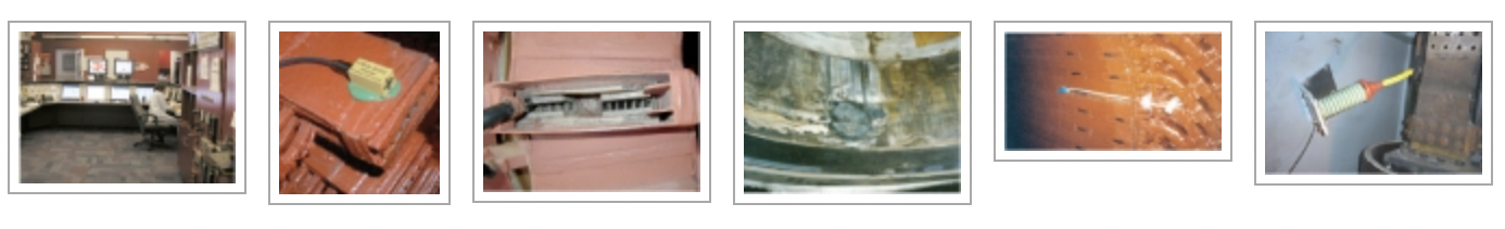
But the situation can be mitigated somewhat by optimum use of the capabilities of a modern distributed control system (Fig 1). A well-programmed DCS can provide operators valuable guidance regarding corrective actions in the event of an alarm or abnormal output from the available instrumentation. This capability is particularly valuable given that generators typically alarm infrequently on several of the devices—for example, stator-winding RTDs and TCs, and generator condition monitor.
The following section describes the types of generator monitoring equipment available to you and summarizes the value proposition. It is divided into mechanical, thermal, electrical, and PD monitoring equipment.
Mechanical
Field vibration. To balance and properly monitor the mechanical performance of a field, vibration levels associated with its rotation must be measured accurately. This can be accomplished by installing shaft-riding or proximity vibration detectors directly on the journals. They are vital for assessing problems such as vibration related to field temperature and/or current. If both vibration magnitude and angle are measured, you can determine the length and angle of a “thermal vector” and identify the optimum corrective action.
Stator end-winding vibration. Generators larger than about 100 MW have a history of in-service failures caused by excessive stator end-winding vibration. Problems can result from both general and locally resonant vibrations. Vibration detectors now available can be mounted safely on stator end windings (Fig 2). They are relatively easy to install but because they still are relatively new, some technical assistance may be necessary.
These detectors allow for the first time routine and accurate measurement of end-winding vibration levels. This is an important advancement because heretofore end-winding vibration has been a major cause of generator forced outages. The instrumentation allows trending of general and local end-winding vibrations to help determine when an outage should be scheduled.
Thermal
Generator-condition pyrolysis monitors identify local and general sources of excess heat. With the addition of temperature-sensitive paints, there’s a general indication as to where the problem may be occurring.
Early monitors were vulnerable to malfunction, particularly if not maintained in good condition. Such malfunctions were conducive to false alarms. Excessive false alarms at some plants caused operators to disregard alarms altogether, which was a mistake in at least a few instances where generators failed in service because alarms were ignored.
However, current models—those produced after about 1990—are more reliable and can be a valuable monitoring device. These instruments are offered by Environment One Corp, Niskayuna, NY, and General Electric Co.
Stator-winding RTDs and TCs. There’s a strong inclination for plant personnel to operate generators based on measured winding temperatures. But the information obtained from the standard resistance temperature detector (RTD) or thermocouple (TC) is only peripherally related to the actual temperature of the winding copper.
Reason is that these devices typically are embedded in the slot where they read a temperature average of surrounding media: tooth iron, cooling gas, and copper (through a thermal insulation blanket). This “average” temperature typically is 20 to 30 deg C lower than the actual temperature of winding copper.
On generators with gas-cooled stator bars, OEMs may locate sensors to read the outlet gas temperature from a few stator bars—typically one TC per half-phase, or a total of six. These TCs are valuable because they can immediately identify a failed bar connection in a typical two-parallel-circuit bar structure.
For water-cooled windings, TCs typically are located in the water discharge circuit from each bar or pair of bars. However, in many designs, a common outlet is used for top and bottom bars. If this is the arrangement on your generator, be aware that if one of the bars is starved of coolant flow, or if no flow exists, the TC may not be sensitive to that condition.
Furthermore, on some designs the connection rings are cooled in series with selected stator bars, and it is important to separate the TCs into the two comparable groups when evaluating readings. The net result: It is difficult to determine if the generator is malfunctioning, and predicting winding maintenance requirements becomes challenging.
Electrical
Field grounds. Both single and double field-ground conditions can be hazardous to both personnel and equipment, which is why industry standards recommend that the unit be brought offline in the event of a field-ground alarm. Industry focus is on the hazard associated with a double ground in a field winding.
But remember that single grounds frequently result from a break in the copper winding. In all such cases, the ground likely is associated with arc burning of the field forgings. This damage can be rapid and severe (Fig 4). The field-ground device offers no information as to where the ground might be within the field, or external to the field.
Field inter-turn short detection (flux probe). Field inter-turn short-circuit detection equipment has been available for many years, but only relatively recently has this device come into extensive use. The field must be removed to install a permanent probe (Fig 5) and the field slot wedges under the probe region must be non-magnetic in order to obtain a reading on the slot. Ordinarily, the latter is not a problem.
The flux probe is highly reliable, with little exposure to error or ambiguous readings. It can determine the precise coil in which the short exists, and can detect a single-turn short in a 30-turn coil. However, it offers no information as to the axial or radial position of a short. Flux probes are available from all major OEMs and Generatortech Inc, Schenectady, NY.
Although isolated shorted field turns are undesirable, their existence is not necessarily a serious concern. If generator operation is satisfactory—that is, vibration levels are within spec and field current is not excessive—an immediate outage to perform the complicated and costly repair may not be warranted. In this situation, it may be practical to plan for a short-turn investigation and repair at the next scheduled outage.
Collector/brushholder rigging. There’s no direct monitoring of collector performance, other than measuring cooling-air temperatures in and out. Significant brush arcing will cause erratic readings on field temperature instrumentation, thus providing an indirect indication of possible trouble. Collector performance must be monitored by direct daily observation (access www.combinedcyclejournal.com/archives.html, click 1Q/2010, click “Maintaining carbon-brush collectors” on cover.
Because ongoing maintenance is needed to keep collectors functioning properly, they are a major cause of generator forced outages. There are particular concerns on small machines without the insulated cartridge brushholders that allow safe and easy online brush maintenance.
There is a special concern with designs not having constant-pressure springs because frequent contact with exciter voltage is necessary to keep spring pressure within correct limits. Fortunately, there are now direct drop-in retrofit brushholders available that incorporate insulated handles as well as constant-pressure springs.
Shaft currents can be destructive, so when problems or concerns arise about them, consider adding sensors to detect their presence. If a reliable insulation system has been applied to the proper bearings, and if good shaft grounding is maintained, the probability of damage caused by current flow should be small. But shaft-current measurement may be useful on machines where a concern exists.
Partial discharge
With good sensors and monitoring instrumentation, it is possible to obtain considerable information on machine condition from the PD occurring in the generator. Interpretation of the data’s significance is the most difficult aspect of partial-discharge testing. Equipment is available from several suppliers, including most OEMs. Sensors typically are installed on the line buss; installation is relatively simple (Fig 6).
Data analysis. Testing-company approaches to PD data analysis are not standardized. One major PD vendor has relatively simple procedures and instrumentation, and a very large database. This allows a generator owner’s engineering personnel to collect and analyze their own data with nominal training.
Other testing vendors prefer to collect the data with their own personnel and instrumentation, and then forward the results to a central engineering group for analysis. Both approaches have given good results in monitoring generator performance.
In several cases, units have been removed from service to investigate high readings, thereby allowing the correction of significant problems before major damage occurred. While some judgment of winding quality is made on absolute readings, all vendors rely heavily on trending of readings over time for a given generator. A winding trending rapidly upward is monitored closely and, depending on readings, may be disassembled for inspection.
While PD monitoring now is common on generators, partial discharge generally is not a major destructive mechanism on mica-based insulation. But PD readings have been found very useful in monitoring stator windings for some critical deterioration mechanisms. Analysis of databases at testing companies with significant amounts of PD data indicate that serious maintenance issues have been found on about 6% of generators.
What can’t be monitored—yet
Some deterioration mechanisms not assessed by monitoring equipment are discussed below. Note that these important mechanisms often lead to in-service failures, some catastrophic.
Stator-bar vibration historically has been a significant root cause of service failure. It tends to cause relatively fast-acting forms of deterioration, with failure occurring within several months to a few years.
Unless bar vibration produces PD or sparking, it won’t be identified by any instrumentation available today. The vibration simply will continue—in most cases at an accelerated rate—until the insulation is worn thin and fails, or the vibration results in fractured and failed bar strand copper.
Stator-bar strand-header water leaks. Leaks in the strand-header connection braze are a slow failure mechanism, often taking several years to emerge as problematic. These leaks have resulted in many stator partial and full rewinds—and a few in-service failures. Leaks may be as small as a few ounces of water a week. There is no monitoring device to detect the insulation dampness that occurs from such small leaks, which will continue until an in-service failure, or until it is found by hipot.
Stator-winding connection cracks typically develop over relatively short periods of time—perhaps two or three years of operation, or less. The primary root cause tends to be resonance vibration, which may start immediately after the winding is placed in service if it has not been designed properly and tested.
Or the resonant vibration may develop over a few months or years, as the component’s natural resonant frequency decreases into the driving frequency range because of operating temperature and winding wear. Unless vibration detectors are installed in the correct locations, there is no instrumentation which will detect this usually severe deterioration mechanism.
Field coil/turn distortion develops slowly—over many months to several years. There is no way to monitor this condition as it develops. Eventually, deterioration may be detected by developing turn shorts, large increase in required field current, vibration, and/or field ground.
Field-turn cracks generally develop slowly—over a period of from a few to several years. There is no detection until fracture occurs. At this point, current will continue to flow (as in a welding arc). The arc will quickly burn through the insulation and give field-ground indication.
But since industry standards focus on the hazard of a possible second ground, it is unlikely that the generator would be tripped immediately. Thus, arcing and burning of the winding and forgings would continue until vibration levels trip the unit, or components start to fracture, or the machine is removed from service for investigation.
Retaining-ring corrosion and cracking. There is no monitoring of this extremely serious deterioration mechanism, which may occur rapidly. In one recent case, just 18 months after an 18/5 retaining ring had been removed and found satisfactory based on a full NDE (nondestructive examination) series, the ring failed catastrophically. There was no warning of impending danger.
Forging cracks. All forged components in the rotating field are subject to possible cracking. In particular, cracks are being found on the field forging under the retaining-ring shrink fit and the body axial centerline. These cracks seem to identify with designs of specific manufacturers. In general, there is no detection capability for such cracking unless it becomes so large as to affect field vibration.
Concluding remarks
Accurately predicting the timing and scope of maintenance needed on an operating generator is not possible with present state-of-the-art monitoring instrumentation. Even with the best monitoring systems, generators remain with little or no detection capability for several of the more common and serious deterioration failure mechanisms.
The age-old industry practice of five years between inspections certainly is not appropriate for many generators because of their infrequent operation, light duty, age, and relative importance to the system.
However, a 10- or 12-year period between generator inspections seems inappropriate for many machines—such as those (1) in continuous high-duty operation, (2) with known or generic quality issues, or (3) of vital importance to the system. Arbitrary extension of maintenance intervals can result in long, costly, inconvenient, and potentially hazardous forced outages.
Maintenance intervals should reflect all known information on a specific generator, including the following:
- Operating hours.
- Operating duty.
- Importance of the unit to the system.
- Results from previous inspection and maintenance outages.
- Availability of replacement parts.
- Condition assessment based on information gathered by monitoring instrumentation. CCJ
Clyde V Maughan is president of Maughan Generator Consultants, Schenectady, NY. He has 60 years of experience in the design, manufacture, inspection, failure root-cause diagnostics, and repair of generators rated up to 1400 MW from the leading suppliers in the US, Europe, and Japan. Maughan has been in private practice for the last 24 years. He spent the first 36 years of his professional career with General Electric Co.