
Response to R2 blade issue quick, thorough
Ever have “management” ask: “Why have you budgeted so much money for industry meetings next year? We have to cut expenses, not increase them!”
Of course you have.
Also likely is that you’ve been a power professional long enough to expect that question from someone who never stood a shift on the deck plates. One who knows relatively little about the diversity of issues you face daily and the value of user-group meetings in helping your staff deal successfully with the challenges of operating and maintaining critical revenue-producing assets.
A good example of user-group value to electric power generators is found in the so-called “R2 blade issue” on the minds of owner/operators of 501F gas turbines at the time of the organization’s 2011 meeting last February. Recall that liberation of cracked R2 blades had occurred in four machines (nearly 2% of the operating fleet) between June and mid October of 2010; owner/operators wanted to understand why and what steps could be taken to avoid potential catastrophic loss.
 It appeared that the majority of users attending the annual meeting were “aware” of the issue upon arrival. That was expected. Bad news travels fast via the user group’s online message board (501F owner/operators can register at http://501f.users-groups.com). Plus, the OEM had called its customers with a “heads-up” and the OEM’s competitors were out in force selling replacement R2 blades.
But most attendees didn’t know much more than their machines had a potential problem and what they had to inspect to be sure their equipment was healthy. The steering committee, chaired by Russ Snyder of Cleco Power LLC (sidebar), developed a special program on the topic to put everyone on the same page, so to speak, regarding background on the issue, how to inspect, damage assessment, repair/new-part options, etc.
If forced to hire a consultant to provide the same information you would have been facing a significant unbudgeted expense. Gathering the needed information on your own easily could have taken weeks by the time you gained access to the people you believed where the ones to talk to. The committee knew exactly whom you needed to hear from and they were invited to, and participated in, the meeting at the Paradise Point Resort & Spa inSan Diego.
The bottom line: In a matter of a few hours, attendees had virtually all the information they needed for decision-making regarding the R2 issue. Plus, they had the opportunity to speak first-hand with colleagues who had the misfortune of being a statistic. Conservatively speaking, this portion of the meeting alone was worth many times the total cost of attendance.
R2 blade issue revisited
In case you didn’t attend the conference and would benefit from a backgrounder on the issue, here’s an overview, developed by the editors, of the material presented. Issues with R2 blades from Siemens Energy Inc and Mitsubishi Power Systems Americas Inc (MPS) first were identified in 2000. The OEM addressed those by redesigning the platform with an undercut and preventing platform contact. The original design and an undercut fix are shown side by side in Fig 1. A blade failed in 2005, but it was of the original design that was modified at repair after a service interval. Until last summer, the undercut blades had recorded years of reliable service.
The “facts” surrounding the four failures in 2010 are the following:
- Liberation has been reported only in repaired R2 blades.
- The 2010 R2 blade separations occurred only in 501Fs of Westinghouse design. Two of the four failed blades were repaired by Siemens, the other two by third parties. All engines were at or close to their rated outputs when the blades liberated.
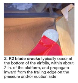
- Cracks typically occur at the bottom of the airfoil, within about 2 in. of the platform, and propagate inward from the trailing edge on the pressure and/or suction side (Fig 2).
- Crack initiation is by low-cycle fatigue; the fracture can then propagate in LCF or high- cycle fatigue.
- A user said the OEM recommended the immediate removal from service blades with cracks 0.4 in. long or longer.

One concern of users was that the propagation rate of any crack found could not be estimated with a high degree of certainty. Another: Collateral damage occurring as a result of a repaired-blade separation likely would be at the owner’s (and/or insurer’s) expense.
Thus buying a new row of blades to mitigate risk seemed like a good strategy for any owner finding cracked blades. For budgeting purposes, figure about $1.3 million to reblade R2—including new parts and labor. That’s not much compared to the $40 million or so it could cost if you wreck the machine.
Owners and insurers are pretty good at arithmetic and they all seemed to decide that new blades were a prudent investment at about the same time. One owner alone was said to purchase nearly two dozen sets of R2 blades. No surprise that the OEM didn’t have enough blades available to meet customer demand.
Alternative suppliers responded: MPS and PSM jumped at the opportunity to offer their blades; Allied Power Group developed a procedure for modifying sound blades in a manner that would preclude their cracking.
The steering committee assured all the suppliers podium time. The following notes summarize key points of those presentations:
Siemens packed 27 slides with technical detail of value to virtually every 501F owner. This and the other Siemens presentations are accessible by owner/operators of the OEM’s frames who apply for and are registered to access the manufacturer’s Customer Extranet Portal. If you qualify for access and are not yet signed up, and need help navigating the registration process, contact your plant’s Siemens representative.
The OEM’s presentation spoke to the company’s root-cause (RCA) investigations and technical developments, field inspection results, new inspection tools, experience with its advanced R2 blade, manufacturing program for advanced blades, etc.
 The first few slides reviewed blade issues identified in the 2000 timeframe and how the OEM responded with design changes to extend the LCF margin and prevent HCF. Field inspection results also were reviewed, complete with statistical analysis. One takeaway: Crack indications were found on half of the engines inspected.
There was considerable discussion of the inspection process and inspection tools. The recommended multi-level inspection process consists of the following:
- A visual inspection enhanced by 20X magnification, preferably with parts out. Includes a macro-inspection of the trailing-edge fillet region to identify any indications.
- Acoustic thermography, to identify base-metal cracks under the thermal barrier coating. These cracks are not visible using 20X magnification.
- Micro-focus x-ray, to identify casting defects and variations in materials thicknesses.
This time-consuming process certainly is valuable for baseline inspections. Reason it is “over-kill” for follow-on inspections: You’re not going to find any new casting birth defects after the first inspection. To speed up inspections at the required intervals, a videoscope can be used for visual checks while the engine is at 300F and on turning gear. This means you can get into the unit within about 15 hours after shutdown and save the day of additional engine cooling required to use a conventional borescope. Additional checks can be conducted when units are being overhauled.
Latest news. Siemens updated users on the R2 issue at the CTOTF’s Fall Turbine Forum in mid September. The company’s engineers noted that experience with Siemens’ “advanced” R2 blade, designed to improve on the undercut blade (the second generation R2 airfoil) associated with the failures, has been excellent to date. About two dozen gas turbines are now equipped with advanced blades; the fleet leader has a nominal 30,000 hours of service and more than 300 starts.
The engineer also said that since the 501F meeting, three conditions for failure have been identified:
- A low-cycle fatigue (LCF) crack of at least 0.2 in. in length. Investigators found several sites with trailing-edge cracks longer than 0.4 in. without liberations. The advanced R2 blade improves the LCF margin to eliminate one of the necessary conditions.
- A blade that is responsive in mode 1 (420 Hz).
- An engine driver that provides a sufficient nominal 420-Hz excitation in R2.
Potential contributors that have not yet been ruled out:
- Platform contact.
- Repair/service debit on fatigue resistance of the base material. Heat cycles in a repair process can contribute to LCF cracks. Recall that liberations have been reported only for repaired R2 blades.
PSM’s rapid-fire presentation on its R2 blade solution is summarized by the following bullet points:
- The company conducted RCA investigations on three of the four blades that failed in 2010. All had the OEM’s undercut mod and had failed after the first repair cycle, as noted above. PSM’s conclusion: The undercut mod was insufficient to fix the problem; the location of the trailing-edge pedestal would still drive unacceptably high stress concentrations. Crack initiation can be expected before 500 cycles.
Keep in mind that PSM’s conclusions are based on an analysis of the OEM’s “current” blade design and that they may not be valid for Siemens’ “advanced” blade design now being offered.
- The third-party supplier said its original R2 blade has an optimized trailing-edge pedestal arrangement and an undercut extending beyond the airfoil trailing edge, which reduces stress levels to acceptable levels. The company representative added that PSM has installed sets of these blades in more than 20 gas turbines and they have a demonstrated a 24,000-hr repair interval.
- PSM’s “improved” R2 blade is said to incorporate additional optimized geometric modifications and some tailored cooling augmentation, the details of which are patent pending. These blades, already installed in operating units, are available for commercial sale as three-interval-life parts.
The Mitsubishi speaker noted that the original R2 blades for M501 and W501 engines were the same, but that his company believed the internal arrangement of cooling passages contributed to an uneven thermal profile across the blade. This contributed stresses that were conducive to a thermal/mechanical overload condition.
Mitsubishi’s solution was to upgrade the blade material to that used in its G- and J-class machines and improve the trailing-edge hub structure and cooling arrangement. The upgrades reportedly have solved the trailing-edge cracking issue associated with the original blades. The company’s R2 blades offered for Siemens machines are expected to run for 24,000 hours/900 starts before repairs are necessary. Projected service life is 48,000 hours/1800 starts.
Allied Power Group LLC offered a solution for owner/operators wanting to save some money—particularly those with one or more spare sets of R2 blades in their warehouses. Allied used its F-class repair expertise to arrive at an upgrade solution that the speaker said would get predictable life from parts on hand.
He stressed thorough inspection, design mod, and enhanced cooling as critical to success. Inspection is important because you have to remove from the pool any blades with an existing crack or inferior casting. Next, the undercut is increased. Note that all machining is outside the coated area. Finally additional cooling is made available at the trailing edge.
The speaker said that a set of blades removed from the warehouse typically can be upgraded within two weeks for less than half the cost of new blades—if you can get new blades. Upgrade of well blades in an in-service set can be accomplished in about three months, including removal from the engine, tip repairs, recoating, etc.
Open discussion
The first discussion session focused on safety, which always generates a great deal of interest. Users summarized incidents at their plants that their colleagues would want to avoid, including the following:
- A contractor cleaning a plate-and-frame lube-oil cooler used a process that caused pinhole leaks in the heat-transfer surface that were not identified until 900 gal of oil was discharged to the river running alongside the plant.
- Air-inlet-house fires still occur on occasion. Attendees recommended that no hot work be allowed without proper supervision by qualified plant personnel; also, that no hot work ever be allowed near hydrogen coolers and other equipment/areas where the potential for explosion exists.
- Stack corrosion was presented as a safety threat. One attendee said a leaning stack was thought caused by high wind. Turns out that severe corrosion in a section of the stack operating at the dew-point temperature weakened the structure and it nearly came down on a windy day. Stack had been in service about 15 years. Periodic thickness measurements were suggested to avoid such surprises.
- There was considerable discussion about chemical accident prevention plans, especially regarding ammonia. New regulations are making the handling and storage of ammonia ever more difficult. The amount of time preparing compliance paperwork and accommodating audits is on the upswing. The users generally agreed that you can expect still more inspection and regulation—including the testing of employees’ knowledge of system operations.
- The importance of arc-flash surveys received meaningful air time. Proper clothing was included in the discussion. An important point was that while most personnel respect 4160-V motor control centers some approach 480-V MCCs casually—a big mistake. One example given was contract HVAC maintenance personnel working on air conditioning equipment. Most often these people are not professional electricians and don’t know about arc flash.
- Stored-energy concerns associated with the starting package, the health risks associated with at least one phosphate ester control fluid, and several other topics also were discussed.
Flow elements for main steam lines were the subject of a special user presentation. The speaker reminded his colleagues to visually inspect these components at a minimum—such as by checking for hot spots in the insulation. Cracking has been found in multi-metal flowmeters (stainless steel venturis in P91 systems) at dissimilar metal welds.
These should be replaced with flow elements made entirely of P91, the user said. About the time of the construction boom (late 1990s-early 2000s), the prevailing wisdom suggested that stainless venturis offered erosion resistance that P91 might not. Experience has shown otherwise.
A flashover solution for air-cooled-generator insulating cleats was the next presentation. Plant had a second flashover a year later. Dust and moisture were thought to be the root cause. Interested owner/operators should access the presentation at http://501f.users-groups.com for its instructive photos.
The combustor section roundtable began with a discussion of dynamics problems and solutions. Several users said poor repairs were a primary cause. Use of third parties for repairs was suggested by some who believe they offer faster service at lower cost than the OEM. Resonators were discussed as the preferred OEM fix. Tuning and flashbacks were also addressed.
Experiencing with the greasing of gas-turbine trunnions is something you don’t normally hear about at a user meeting. Pumping grease between the trunnion bearings can be a challenging job, the speaker said—one that may require jacking of the turbine to assure proper greasing. The presenter has a base-load unit and greasing is done annually; a user in the audience said they do it every two weeks on their peakers.
The life of grease in such demanding service is short and good greasing is important, it was said, to minimize unnecessary vibration. General agreement among the few contributors to this dialog was that Dupont Krytox XHT-BDZ is the best product for gas-turbine service, but it is very expensive.
There are good photos in the two presentations posted to the user group’s website—including a new 15,000-psig grease gun and the putty-like consistency of grease that has “cooked.”
The compressor discussion zeroed in on the heavy strongback mod. By show of hands, plants represented by about two dozen users in the room had implemented this upgrade. Most appeared generally satisfied. One user said he believed that an alternative offered by another OEM was “better.”
The hot-section roundtable addressed belly band/interstage seals, blades, parts fallout, and coating improvements. One participant noted that 30% of his plant’s R1 blades had to be replaced after only 8000 hours of operation.
Downstream deflection of R3 vanes was part of the discussion. Not too long ago, a couple of users agreed, these vanes could be repaired only once. But now, they said, some shops are adept at accounting for downstream deflection for up to three repair cycles.
Shroud-tip liberation of an FD3 R4 blade, belly band cracking/gaps, and four-way joint cracking also got air time.
Interest in low-load turndown has grown dramatically in the last several years, and with the need to back up intermittent renewables a requirement in many areas of the country, the upgrade soon may become a necessity for some power producers. In brief, LLTDenables engines to operate with CO emissions at 10 ppm or lower down to 50% of rated output. The actual lower operating limit depends on ambient conditions and 50% might not always be achievable at your site every hour of every day.
The ability to operate at low loads helps users reduce cycling frequency, which contributes to longer maintenance intervals and higher reliability and availability over the long term.
The scorecard of LLTD experience: The upgrade has been retrofitted on three gas turbines inNorth Americaand built into 14 new units, seven of which are already operating. The fleet leader passed 4000 EBH (equivalent base-load hours) of operation in the turndown mode in January 2011.
Extending the inspection interval by 50% increases plant availability and reduces life-cycle costs. The speakers said the technical scope for increasing the maintenance interval from 8000 to 12,000 hours included upgraded pilot nozzles and support housings, thick TBC (thermal barrier coating) on the resonator baskets, modified transition pieces, and thicker wear strips on transition seals.
The OEM’s performance upgrade package to convert FD2 models to FD3 (including single-piece exhaust) passed the 10,000 EBH mark (104 equivalent starts) on the fleet leading gas turbine in November 2010. There also are more than two-dozen FD3s designed from the ground up in operation. The fleet leader in that group has more than 30,000 EBH.
Other performance enhancement products include ultra-low-NOx combustion systems, low-CO startup products, fuel conversions, and fuel flexibility products—and LLTD, of course. A big benefit of performance enhancement products is a significant reduction in mass emissions per megawatt-hour of electricity generated.