
Recognized for its Best Practice pertaining to Electrical Systems
Upgrades to non-segregated bus duct help prev ent faults
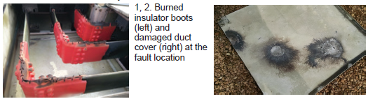
Two electrical faults occurred on a 13.8-kV bus within five years at Minnesota Municipal Power Agency’s Minnesota River Station, operated by NAES Corp. In both incidents, the solid copper bus and ductwork sustained extensive damage, resulting in lengthy forced outages. Figs 1 and 2 show the burned red insulator boots and damaged metal duct covers at the fault location.
During the first incident, the plant team, directed by PM Bob Burchfield, coordinated with the OEM and determined that the section of bus where the fault occurred had insufficient heating. Two new heaters were installed and inspections were scheduled more frequently.
Five years later, a fault at a different location required a more extensive investigation and more robust defense. Both events had occurred during conditions of extreme humidity with heavy rainfall and dew points above 73F.
A third-party engineering firm determined that the bus was designed for relative humidity of 95%. However, relative-humidity levels routinely exceed 95% during the spring and summer months in the region. Ductwork is vented to atmosphere through small screened holes, exposing the bus to ambient weather conditions.
While making repairs after the second incident, staff noticed that the OEM had modified the replacement parts. The red insulating boots now had the tie-wraps at the sides rather than on top. Previously, they had allowed moisture accumulating on the upper cover to drip into the seams and onto exposed copper bus. The OEM had also modified the metal duct covers to create more overlap, particularly on the corners.
After the plant had completed repairs with improved OEM parts and added another space heater, the insulation readings still remained below acceptable values. Infrared imagery revealed that the heaters added negligible heat to the actual duct. Staff also noted that the new heaters purchased from the OEM were installed inside the duct with minimal clearances from the bus, apparently to make them more effective.
After heating the bus for a prolonged period following repairs, technicians found that phase-to-ground resistance readings remained below acceptable limits. They injected dry air overnight using a makeshift regulator and hose, which significantly improved insulation and permitted the bus to be energized safely.
Given the success with this arrangement, technicians designed a dry-air supply system for permanent installation and wrote an operating narrative explaining multiple safeguards and interlocks to prevent over-pressure and use of a permanent dry-air injection system to prevent moisture entry. The slight positive pressure created by injecting air, they noted, is an added benefit of the injection system.
Staff learned from the repair contractor that many sites in the region had experienced similar failures, and in some cases, simply doubled the number of space heaters as a corrective action. However, Minnesota River ruled out the “additional heaters” option because the OEM’s new locations for space heaters inside the bus provided less than 4 in. of clearance between the bus and ground. The IR images showed the heaters were less than effective at increasing the temperature inside the duct, even at that proximity.
To be on the safe side, the technicians’ proposed air injection system was reviewed by a qualified third-party engineering firm and by management. Injection of dry air typically is reserved for isophase bus ducts, so there were concerns about applying this solution to a non-segregated bus duct—especially since non-seg bus covers are fastened with screws and not necessarily designed for positive pressure.
Recall that isophase bus duct generally is constructed of welded tube with only one conductor per duct.
In their narrative, the technicians explained how they would provide equal flow to each injection point using instrument throttling valves and a flow meter to measure the incremental air-flow increase at each injection point. At the same time, they confirmed low pressure with sufficient air flow by observing a small amount of the a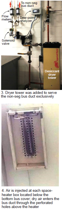 ir exiting the duct from each vent/drain hole.
The following three-pronged approach was taken to prevent water from entering via the supplied-air system:
-
- The team recognized that any malfunction of a regenerating dryer tower could allow water to enter the instrument air piping from the air compressors. Technicians didn’t completely trust the installed plant dryer tower, so they proposed adding a tap to the top of the instrument-air receiver tank plus another dryer tower dedicated solely to the non-seg bus duct (Fig 3).
- Staff also procured and installed a dedicated dew-point analyzer and programmed it to shut off the air-supply solenoid at a predetermined set point. The normal dew-point temperature downstream of two dryer towers is very low, so a conservative shutoff set point of 0F was selected. Part of the logic in being this conservative was that the dew point remains relatively constant in the new system, so a change of any appreciable amount could indicate a problem.
- Air is injected at each space heater box located below the bottom bus cover; dry air enters the bus duct through perforated holes above the heater. If water reaches this box from the air supply, it has a last chance of removal through the bottom screened hole (Fig 4).
The sheer size of this particular bus factored into the solution. The duct measures approximately 200 ft long and consists of three different sections. It is heated by 25 space heaters powered by two separate 120-V circuits; each heater draws slightly more than 1 amp.
The team procured and installed a current monitoring device. If any heater open-circuits, the current draw will drop by 1 amp. If an entire heater circuit trips, the new panel will display a loss of current. An alarm was not provided because a thermostat periodically will shut off heaters at 95F and this would cause nuisance alarms.
The dry-air injection system has been in place for two years. During a series of severe storms in 2017 that brought heavy rains, 80- to 100- mph winds, and many days of high relative humidity there was no arc-tracking and no evidence of moisture intrusion. Phase-to-phase and phase-to-ground insulation resistance readings remain much higher than pre-installation values. Staff needs more time to fully determine the new system’s effectiveness, but if it had not been in operation during last year’s extreme weather, another electrical fault likely would have occurred.