


A cornucopia of information, the ideal meeting for time-challenged managers
 The CTOTF™ Leadership Committee, chaired by Bob Kirn of TVA, consistently delivers on its promise to provide coverage of the entire plant at each of the organization’s semiannual meetings. At the user group’s four-day Spring Turbine Users Conference last April in Virginia’s Williamsburg Lodge, 17 interactive user sessions totaling 67 hours of presentation and discussion time took the more than 100 plant and asset managers in attendance from the gas transmission line to the plant’s connection to the high-voltage grid. Key points from these sessions are summarized below.
In addition to sessions dedicated to specific types of gas turbines, other critical equipment, industry issues, O&M and business practices, and regulatory and compliance matters, the meeting featured several special events, including the following:
- Presentation of the 2012 Best Practices awards recognizing the valuable contributions made by plant staffs—and headquarters personnel—to improve the performance of generating facilities powered by gas turbines (details in companion article, p 94).
- A trade show involving more than five dozen companies that offer equipment and services to generating stations.
- CT-Tech™, an additional training opportunity offered by CTOTF, provided expanded instruction on contamination solutions for gas-turbine lube and hydraulic systems. The three-hour evening program was conducted by subject-matter experts from Hy-Pro Filtration.
- A tour of Alstom’s rotor overhaul shop in Richmond (sidebar).
GE F-class engines
A properly operating combustion system is critical for achieving desired gas turbine performance while maintaining pollutant emissions at or below permit limits. That’s certainly not news, but many people with responsible deck-plates positions who came into the industry after the millennium are not fully aware of how challenging it can be to keep a late-model F-class engine “tuned” to meet expectations and why this is so.
Robert Bland, chief design engineer for Wood Group GTS’s Combustion Engineering Systems and Technology Solutions group, provided a backgrounder on dry, low-NOx (DLN) combustion to help users make better O&M decisions. The combustion expert shared his knowledge with owner/operators attending CTOTF’s GE F-class roundtable. Pierre Boehler of GenOn Energy Inc and Mike Hartsig of NAES/Griffith Energy are the chair and vice chair, respectively, of this popular session, which is featured at the organization’s spring and fall meetings.
CTOTF normally restricts presentations by non-users to 30 minutes or less, but it set aside two hours for Bland’s “DLN2 Combustion Configurations” and follow-on discussion because of the subject’s importance to attendees. Bland was equal to the task and with his depth of knowledge easily could have conducted a full-day workshop. The combustion expert moved quickly though a mountain of information contained in about five dozen slides, taking questions at the convenience of attendees.
Participants who knew the most about the subject matter probably benefitted the most given Bland’s word speed. His PowerPoint is posted to CTOTF’s extensive Presentations Library at www.ctotf.org, enabling users who were unable to attend the meeting to benefit from its extensive content. If you have not yet registered for the CTOTF Presentations Library, do so today online—it’s a simple process. The primary requirement: You must be employed by an owner/operator of gas turbines.
Bland began at the beginning, tracing the birth of NOx control in gas turbines back to the early 1970s in Southern California. He seemed to leave no stone unturned, explaining how NOx is formed and how it was controlled prior to the development of DLN combustion systems—by quenching the flame with water or steam. This was a suitable approach initially, he said, because a water-to-fuel ratio of 0.5 could reduce NOx emissions on an oil-fired unit to about 75 ppm.
But California demanded still lower emissions. By the end of the 1970s, a water-to-steam ratio of 1 was required to reduce NOx to the 42 ppm on gas required in some areas. Such a significant amount of water or steam can adversely impact combustor performance and economics, Bland noted. For example, CO discharges and combustion dynamics increase and the cost of treated water, which cannot be recovered, reduces profitability.
Engineers believed that the diffusion-flame combustion systems in use at the time (Figs 1, 2) were in conflict with the goal of lower emissions and supported switching to a premixed flame. Recall that the diffusion flame gets its name from the process by which air (oxygen) combines with the fuel (by diffusion); a premixed flame is one where oxygen and fuel combine before the mixture reaches the flame front. Premixed flames burn at a lower temperature than diffusion flames and therefore produce less NOx.


Discussion of the DLN1 series of premixed combustion systems (Fig 3) installed on GE 6Bs, 7EAs, and 9EAs—and early 7FAs and 9FAs as well—was a good segue to the DLN2 family for the OEM’s 6, 7, and 9 FAs and FBs. The first combustors in this series were called DLN2 (Fig 4), followed by DLN2+, and later by DLN2.6+ (Fig 5). Bland told the users not to think that combustors with the same model number are necessarily the same. They may look the same, he said, but they can differ with frame type, year of commissioning, and other factors.
It’s difficult to design an optimal combustion system to suit an entire series of engines, the expert continued. Reasons include (1) the design of engines in a given model series varies over time based on operating experience, (2) today’s replacement hardware may be different than the parts installed during the last overhaul, (3) operating paradigm can change over time, etc. Additionally, consider that the combustion system installed in your new turbine probably is designed for 12,000 hours or longer. You make adjustments three or four years later during the first hot-gas-path inspection and then you’re back in service for another three or four years before you see if what you did corrected previous issues.


Bland then dug into the details of the DLN2, 2+, and 2.6+ to show attendees how the combustion system evolved. For example, the DLN2 was introduced on the 7FA (7221) in 1994 as a 25-ppm system. It was last installed in 1999. There were infant mortality issues to be sure—including dynamics so severe the system sometimes wouldn’t operate during trials, flashbacks into the premixer, etc. The five-nozzle DLN2 was modified by addition of a center nozzle to DLN2.6, first installed on a 7FA+ (7231) to reduce NOx emissions to 15 ppm.
Turbine redesign, which released more air to the combustor and reduced combustor pressure drop, enabled the DLN2.6 to limit NOx emissions to 9 ppm for the 7FA+e (7241) engine. For background on the DLN2.6 and its operation, access “Preventing blowout trips of 7FAs” in the CCJ’s 3Q/2011 issue at www.ccj-online.com.
The second half of Bland’s presentation focused primarily on a detailed review of major DLN2.6 components—for example, end cover, flow sleeve, fuel nozzles, quaternary fuel, cap, Swozzle premix fuel nozzles, liner, crossfire tubes, and transition piece. Included was a rich discussion of operational issues—such as braze failures that can allow fuel to leak the face of the end cover—and how to repair same. Guidance also was provided on how many times a given repair could be made.
The final day
CTOTF lumps generators, high-voltage electrical, and I&C presentations and discussions into what it calls the Gen-EI&C Roundtable, which traditionally runs from 8 am to 4:30 pm on the final day (Thursday) of each meeting. SRP’s Moh Saleh is the chairman of this session, doubling as the chair of the high-voltage (HV) component; John-Erik Nelson, Braintree (Mass) Electric Light Dept, is the I&C chair and Craig Courter, Guadalupe Power Partners/NAES, is the generator chair.
Two presentations at the spring meeting receiving high marks from attendees were John Blaney’s, on wireless applications in power, and Paul Griffin’s, on mitigating the risk of a transformer failure. Blaney is a technology leader in Emerson Process Management’s Power & Water Solutions group; Griffin is VP of power services for Doble Engineering Co, specialists in condition assessment and monitoring of transformers, HV switchgear, and generators.
No wires, no limits. In the generation sector of the electric power industry, John Blaney may be the most passionate supporter of wireless communications networks. The controls expert got the session moving on a high note with an entertaining, but serious, technical backgrounder on wireless communications and an overview of the technology’s future. Blaney, who has more than three decades of experience designing, installing, and troubleshooting powerplant control systems, is Emerson Process Management’s point person on PlantWeb® applications for the company’s Ovation® platform.
Blaney’s mission was to get the group to kick back and think of the benefits associated with extending the reach of the plant network using wireless technology. Wireless networks, he said, can be characterized as either field or plant networks. Each serves different applications and has specific requirements for bandwith, power, and standards.
Field networks, formed by wireless field devices and gateways, are configured for process applications, process control, and diagnostics. Typical applications include monitoring of (1) stacks and vents to avoid fines for exceeding permitted limits of pollutants and (2) valve position to ensure equipment is properly aligned.
He told the group that wireless technology has matured from the point-to-point field networks that some attendees recalled as having limited reliability to self-organizing networks, commonly referred to as “meshes,” available as a process industry standard through the HART Communication Foundation. Self-organizing networks are the only industry standard available today, Blaney continued, because they are the only ones capable of providing the reliability of data transmission required for power and process applications.
The ability of self-organizing networks to automatically reroute data to an open frequency/channel, and to the most efficient device for communications, enables data transfer reliabilities of more than 99% regardless of process environment or application, he said—adding that the WirelessHART network automatically adjusts to satisfy plant requirements as your environment and network changes.
The wireless champion pointed out that while it may seem counterintuitive, self-organizing networks become stronger with each device added because the number of communication paths increases. You use wireless, he said, but you don’t have to fully understand it to use it. The WirelessHART experience base currently spans 2500 sites worldwide with more than 300 million hours of operating time in real applications.
Security probably was on the mind of virtually every owner/operator in the room given NERC’s (North American Electric Reliability Corp) emphasis on that subject today. Blaney reported that WirelessHART integrates best-in-class security to protect wireless networks from outside threats. Also, that Emerson’s security approach has been validated and tested by customers and wireless experts. Here are the key elements of the WirelessHART approach to security:
- Data encryption to protect valuable information.
- Ability to authenticate sender and receiver to ensure that only devices within the network communicate with each other.
- Ability to verify that the data have not been changed during transmission.
- Anti-jamming technology, specifically channel-hopping, to avoid interference and improve reliability.
- Automatic key rotation (password management) to protect your network from unauthorized access.
The gateway interface between the wireless field network and the wired network world employs all components of the security solution described above and is responsible for managing security as well. Because the wireless field devices do not use TCP/IP messaging, if an intruder tries to compromise that side of the network, the attempts will be ignored. However, because communication from the gateway to the control system does uses TCP/IP messaging, Emerson relies on industry standard techniques—such as VPN and HTTPS—to assure what the company believes is the most robust wireless security in the industry.
Plant networks. Whereas field networks are used to communicate critical process control information, wireless plant networks serve applications not necessarily central to the basic power-generation process. These include data connectivity, video/perimeter security, voice communication, and people and asset tracking. Plant wireless, Blaney said, relies on commercial off-the-shelf technologies—such as Wi-Fi, which is defined by IEEE 802.11, an accepted industry standard.
Because plant networks use open IT standards, security measures must be added to address evolving concerns. Blaney said this means it’s in your best interest to choose a plant network supplier with the capabilities to address the full range of security concerns to the satisfaction of the IT community. Emerson has done many implementations combining field WirelessHART and plant Wi-Fi networks, he added. Customized solutions are developed to accommodate a specific problem or area of the world.
To dig deeper, access Blaney’s “Benefit by installing reliable, secure wireless communications networks at your plant,” which appeared in the 2009 Outage Handbook published as part of CCJ’s 3Q/2008 issue, available at www.ccj-online.com.
 Transformers represent one of the largest and most critical investments in an electric power system. Paul Griffin told users that mitigation of failure risk begins with a well-designed, well-built transformer. However, an effective maintenance strategy is critical to maximizing transformer performance and reliability, he said.
An integrated program of online and offline testing, and online monitoring, are an important part of this effort, Griffin added. A good strategy is to determine the potential failure modes and establish a surveillance program using matching diagnostics. Failures of windings, for example, can be caused by excessive heat, age, insulation breakdown, and/or mechanical issues. Overheating attributed to circulating currents, and oil deterioration and contamination, are other known contributors to transformer failure.
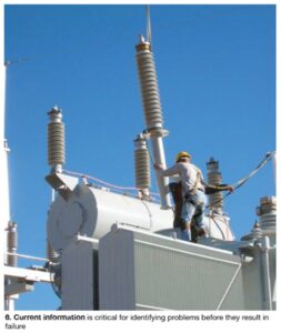
Current information is critical for identifying problems before they result in failure (Fig 6). Griffin pointed to the following information resources available to users: external inspection, laboratory and electrical testing, review of unit-specific historical operating data, review of fleet/design-specific data, OEM service advisories, plant trouble and failure reports, plant personnel responsible for HV assets, etc.
He then expanded his discussion on each of these points. For example, on the subject of electrical testing, Griffin reviewed the value of power factor and capacitance measurements, excitation, leakage reactance, frequency response analysis, dc winding resistance, and insulation resistance.
Next, the transformer expert provided a checklist of information required to conduct a detailed condition assessment. This seemed particularly helpful for any attendee assigned to a due diligence team evaluating an asset purchase. Here’s what Griffin considers important:
- Data from dissolved gas analysis and other oil tests.
- External inspection.
- Results of electrical tests.
- Type of operation—for example, peaking plant, base load, etc—plus loading profile.
- Age.
- Maintenance and repair records.
- Documentation relating to problems and failures.
- Design review.
- Loading profile.
- Transient fault recording data.
- Acoustic analysis.
GE legacy gas turbines
Frame 7B-EA engines are thought to be running more because of low gas prices. This made the CTOTF Leadership Committee believe users would benefit from the latest experiences of owner/operators with end-of-life issues, considering the relatively large number of these machines 25 years old and older.
Correct! Attendee interest clearly was in evidence at the GE Legacy Roundtable, chaired by Pierre Boehler of GenON Energy Inc. Ed Wong of NRG Energy Inc is the vice chair. The user-only discussion that developed from a simple slide with the bullet points below lasted about two hours:
- Generator issues
Field and stator windings.
- Turbine issues
Hot-gas-path (HGP) degradation, Compressor, Casings.
- Balance-of-plant (BOP) issues
Controls and wiring, Piping corrosion, Auxiliaries and other.
There was simply too much information on too many topics to summarize in a few words, so the editors just selected a couple of subjects for coverage. Attendees were the big winners, as always at CTOTF meetings, gaining valuable perspective along with a collection of best practices and lessons learned.
Generators. On the subject of generators, one user reported on a 7B field ground fault that occurred a few years ago. A shop visit identified winding coil distortion and slot insulation burn-through (Fig 7), copper migration and deformation, cracking of about half of the main-lead flex leaves (Fig 8), and other issues—generally attributed to age and demanding service. A full rewind and high-speed balance were required before returning the field to the plant.


First-stage nozzles were part of the HGP discussion with another contributor to the collective knowledge sharing his experience with carbide growth at grain boundaries, chrome depletion, internal cracking in air passages, etc (Fig 9). One of his concerns was the increasing cost of repairs.
Second- and third-stage nozzles of FSX-414 were mentioned because of this material’s tendency to creep. Distortion can exceed the limits for repairs to correct creep, the group was told. Downstream deflection of second-stage nozzles also generated some discussion. Owner/operators were made aware of the consequences of loose dovetails, including the large tip shroud gaps shown in Fig 10. Fixes discussed for worn dovetails included coatings and tri-seal bucket seal pins.
Users also were reminded of obsolete bucket designs, ones out of production—such as the first-stage “sharp nose” design prone to cracking. Shroud-block degradation was another topic brought to the floor, an attendee relating his experience with extensive cracking of first-stage shrouds and heavy erosion of second- and third-stage blocks.


Casing degradation was of considerable interest to the users. Several mentioned experiences with cast casings heavily degraded from rusting and gouging damage. Substantial material loss was reported in some cases, especially at flange surfaces and bolt and plug threads (Fig 11). It seemed as if every exhaust frame suffered from cracking and repeated weld repairs (Fig 12).
Instrument and wiring failures were associated with hot-gas leakage from flanges and casing penetrations that caused high compartment temperatures. There was a report of a turbine shell dropping relative to the exhaust frame because of age and other factors. The result: Rotor position was no longer concentric with stator casings.
Possible near-term repairs suggested:
- Manually dress casings during overhauls.
- Shim large gaps between flanges.
- Weld seal strips across flange joints.
- Install inserts were required.
Casing-alignment checks during major inspections was recommended with the suggestion to relocate bearings 2 and 3 to achieve a “compromise” in rotor position. Long-term repairs discussed included removing casings from the base plate, separating the turbine from the exhaust frame, machining flange faces and bolt holes, realigning the unit, and reassembling with larger dowels. Also noted: Be prepared to replace the exhaust frame and diffuser casings.
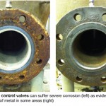 Check for corrosion of gas control valves on dual-fuel units, Young & Franklin’s Norm Gagnon told roundtable attendees during a short presentation. Users having Frame 7B-EA gas turbines with dual-fuel capability should consider inspecting the outlet chambers of combined gas control valves for corrosion at their next opportunity. Corrosion can be severe in some cases (Fig 13). On one unit, 35 mils was removed from the face of the valve’s outlet flange (Fig 14).
The primary purpose of the valve assembly is to regulate the flow of natural gas to the gas turbine’s fuel nozzles. Gagnon said that Y&F’s research suggests hydrocarbons and sulfur entrained in the gas, and purge air, contribute to the issue. Recall that purge air is used to clear fuel nozzles when switching from oil to gas and vice versa and that backflow to the Y&F valve can occur during the purge.
Corrosion has been found on units throughout the US and Canada with problem valves being identified with the use of unheated gas. As a first step, Gagnon recommended that owner/operators assure 50 deg F of superheat in the gas at the valve inlet to be sure there are no entrained hydrocarbons. He also suggested that users review the fuel specifications in GE document 41040F concerning preheat, allowable hydrocarbons, etc.
Regarding inspection of your valves for corrosion, there is a plugged port in the valve discharge nozzle that allows borescope access to the outlet chamber. CAUTION: Before performing this inspection be sure you are in compliance with NFPA 56 regarding proper procedures for working on gas lines.
Combined cycle
Safety has been the No. 1 discussion topic at most user group meetings for the last couple of years. The open forum at CTOTF’s Combined Cycle Roundtable, chaired by Erik Knutson, an assistant plant manager for Colorado Energy Management LLC, and the latest addition to the user organization’s leadership committee, is a case in point as the bullet points below attest. Rick Shackelford, plant manager, Green Country Energy LLC, is the vice chair for this roundtable.
- Attendees revisited procedures for steam-drum door inspection and tightening after a recent industry fatality. Users were urged to develop procedures for torqueing drum doors and for steps to take when a leak is found. Participants generally agreed that attention to detail regarding alignment of the drum gasket is critical to preventing leaks. An attendee volunteered that frequent drum-door gasket leaks prompted his management to order a redesigned drum door from the OEM. Others tormented by the issue were urged to do the same.
- Remote racking devices to avoid arc-flash hazards were acknowledged as one of the most important safety devices in a plant. Not a major expense, users agreed, but a major safety improvement.
- Achieving proficiency in high-angle personnel rescue was a goal of several attendees. It was noted that local fire departments are not often well-trained for this. Suggestion: Use safety harnesses with stirrups to reduce load on legs if someone is hanging. Another: Use a safety harness and winch to lower personnel into locations difficult to access, thereby eliminating the need for rescue.
- Boiler-drum confined-space safety. What if someone loses consciousness during a drum inspection or repair? Does this confined space require a harness? Consensus view: Not at all plants; but there was agreement that a confined-space retrieval plan was necessary.
- Confined-space rescue involves considerable effort and expense for training, certification, and equipment (initial cost and upkeep). Can’t expect much help from budget-constrained fire departments the group agreed. Possible solution: Plant provides seed money to the FD for confined-space rescue activities.
- Two plants partnered to donate a safety rescue trailer and equipment to a local fire department after the FD agreed to pursue training for plant-specific emergencies. Unintended consequence: New fire chief was not interested in keeping the arrangement when he took office. City manager rescued the plan by siding with the plants.
- Downside of working with your local fire department regarding surveillance of confined-space activities: If an emergency call comes in they won’t show up onsite. This can result in unexpected delays during outages.
Nozzle cracking. Owner/operators attending CTOTF’s Combined Cycle Roundtable were told by Scott Wambeke, PE, that HRST Inc’s engineers are finding many more incidents of steam-drum nozzle cracking today than only a few years ago and advised users to inspect all drum penetrations as soon as is practicable. He called drum nozzle cracking a common problem and said it is found most often in downcomer nozzles.
Wambeke reminded attendees that thermal stress, the primary cause of the cracking, is related to steam-drum temperature ramp rate and that drum and nozzle thicknesses determine the allowable ramp rate. The type of nozzle weld is another important factor. Full-penetration welds are much more resistant to cracking than partial-penetration welds, he said, showing a few sketches of the types of drum welds typically used. Weld details also come into play, Wambeke continued, asking users not to forget that sharp inside corners concentrate stress.
Non-destructive examination (NDE) was next. Visual inspection is useful, the HRSG expert said, but not sufficient on its own. Surface NDE is better—that is, dye-penetrant and magnetic-particle inspection methods. Volumetric NDE—shear-wave ultrasonic (UT), phased-array UT, and radiography—is better still for the additional information it provides. Wambeke stressed that if you have been relying on visual inspection only, cracks may very well exist.
Where to look. For pass-through downcomer nozzles and other nozzle welds easily seen from the drum, he suggested that users begin their condition assessment with a visual inspection inside the drum. If there are no visible indications, follow up with mag-particle or dye-penetrant testing. If crack indications are found, nozzle welds also should be inspected from the drum exterior. Riser and steam-outlet nozzles also should be inspected while inside the drum, particularly if cracking of downcomer nozzles is identified. Sometimes access can prove difficult and you may have to remove part or all of the belly pan, or the final steam separator.
For drums with set-on downcomer nozzles with their welds on the outside of the drum, conduct visual and NDE inspections from the drum exterior. Opt for volumetric NDE when it’s necessary to determine crack depth.
Regulatory, compliance
One of the most valuable aspects of CTOTF’s Regulatory and Compliance Roundtable, chaired by Scott Takinen of APS (Alan Bull of NAES is vice chair), is keeping plant management up-to-date on changes to existing regulations and where their attention should be focused. A presentation by Matthew Stryker, manager of CIP compliance monitoring at SERC Reliability Corp, outlined the coming changes and potential impacts to NERC CIP standards.
Stryker told the group that CIP Version 4 is up for FERC approval and, if passed, can lead to some significant modifications to previous versions of CIP-002, in particular. Changes would go into effect about two years after approval. First and foremost, multiple “bright line” criteria, adopted to eliminate subjectivity by entities, would now be used to identify critical assets (CA) and critical cyber assets (CCA) instead of the risk-based self-reporting methodology previously acceptable.
For generation owners, the following are considered CAs:
- A generating plant with a real power capability of 1500 MW or more.
- Reactive power resources with a nameplate rating of 1000 MVAr or more.
- Generating facilities deemed by the transmission planner as necessary to avoid adverse reliability impacts on the bulk electric system (BES).
- Black-start resources.
- Special protection systems, remedial action scheme, or automated switching systems that operate BES elements.
- Facilities that perform automatic load shedding of 300 MW or more.
- Control centers that perform the functional obligations of the reliability coordinator.
A new addition regarding CCA identification for generating plants with a real-power capability of 1500 MW or more states the only cyber assets that must be considered are those shared cyber assets that could, within 15 minutes, adversely impact the reliable operation of any combination of units that, in aggregate, equal or exceed 1500 MW.
Welcome to the club. Results from a recent NERC data request to gauge the number of plants that would be drawn in by Version 4 identify 234 generating units with CCAs having black-start capability and 475 generating units with CCAs because of factors other than black start. This represents a marked increase from the current number of generation CIP assets.
I have identified CCAs. What next? Stryker stressed that a good first step is to consider the cyber assets you have which will require technical feasibility exceptions (TFEs) available for specific standards where achieving strict compliance is not possible (physical security, remote access, anti-malware, password protection, etc). TFEs can take some extra time to put together because it is very important to coordinate with a vendor or developer. About half of all TFEs are submitted directly by vendors on behalf of the plant. Also required is a strategy for terminating the TFE and returning to strict compliance or evidence of why compliance is not attainable.
Next, consult the new NERC CIP implementation plan to understand the timelines associated with standards CIP-003 to CIP-009. Timelines vary from six to 24 months depending on your situation, and during that time, considerations for budgetary concerns, personnel additions/training, and planned outages should be prioritized.
Stryker finished up by providing the following list of resources that will bring you up-to-speed and assist your organization with developing an effective implementation plan:
- New CIP implementation tables.
- Background on CIP implementation and the old implementation tables.
- Identifying critical assets.
- Identifying critical cyber assets.
- Sufficiency review report.
- CIP-002 public NOPs.
- NERC’s case notes for possible violations.
- CIP Version 5 project page.
- TFE procedure.
- NERC Compliance Application Notices.
- CAN-0017 regarding password TFEs.
Pratt & Whitney
A summary of recent borescope-inspection findings by Mike Hoogsteden, field service manager, Advanced Turbine Support LLC (ATS), Gainesville, Fla, pinpointed areas of the FT8 of greatest concern to owner/operators of the expanding fleet. The presentation on the popular aero engine, manufactured by Pratt & Whitney, was made during a special session for FT8 users.
Hoogsteden walked attendees through the engine from the compressor bellmouth through the power turbine (PT). Rubs, tip discoloration, and minor deposits and impact damage characterized typical findings in the low-pressure (LP) compressor. Biggest surprise: compressor case damage. This had not been seen by ATS inspectors until recently and has been identified in four engines thus far (Fig 15).
The service manager’s photos of tip rubs and dings in the high-pressure (HP) compressor didn’t reveal anything every user in the room hadn’t seen previously. An inoperable engine-heater check valve seemed to generate the most interest. Hoogsteden said ATS finds inoperable check valves on 20% of all engines inspected. These valves are critical for keeping engines above dewpoint temperature when they are not in operation.
Wear and tear identified with the combustion section included relatively minor liner coating loss and cracking (Fig 16), plus a damaged J-seal on one engine. In the HP turbine, coating loss in spots is relatively common on the suction side of rotating blades. Erosion at the base of vane segments is found occasionally (Fig 17). Interestingly, erosion occurs gradually and little collateral damage has been experienced in engines inspected by ATS. Erosion can approach the air cooling holes in some instances.
Small areas of coating loss also can be found on the leading edges of LP turbine S1 vanes (Fig 18) and blades. Measurements taken by inspectors in the exhaust-case area can help ATS determine if the gas generator has moved and, if so, by how much. Thinking is that shifting of the GG case could be a factor contributing to R1 air seal damage found in some power turbines (PT).
Additionally, is believed that a crack in the PT’s R1 nozzle retainer ring (Fig 19) may be conducive to a condition known as “lean back,” which also can contribute to R1 air seal damage (Fig 20). Next, trailing edges of S1 vanes are checked for platform wear (Fig 21) and R2 seals are inspected to be sure they’re in good condition. PT rows 3 and 4 are checked for rotor-blade tip shroud rub (Fig 22).


Siemens legacy units
Mike Rutledge earned a 10 in his debut as chair of the CTOTF Siemens Roundtables for conducting, with Vice Chair Rocky Roos, an engaging panel discussion to identify options for making legacy units—primarily simple-cycle engines—more competitive. Rutledge, manager of plant technical support for SRP, moved to his current CTOTF assignment after serving as chairman of the Combined Cycle Roundtable for several years. Roos is maintenance superintendent for Municipal Light & Power in Anchorage, Alaska.
Panelists included the following respected metallurgists and engineers:
- Richard Curtis, VP engineering, Eta Technologies LLC.
- El Williams, Sulzer Turbo Services.
- Greg Snyder, engineering manager, Dresser-Rand Turbine Technology Services.
- Sal DellaVilla, president, Strategic Power Systems Inc.
- Doug Nagy, manager of components repair, Liburdi Turbine Services Inc.
- Scott Wambeke, HRST Inc.
Rutledge lit the fuse and the interactive discussion between panelists and owner/operators in the audience burned for the two full hours allotted. Virtually everyone in the room agreed that the key factor influencing business potential is geography (location/location/location). For example, in the Northeast many units have capacity payments and in this market the most important factor is starting reliability. The grid imposes penalties if you can’t start units as required, and unless you can prove that you actually can meet grid requirements after a failure to meet expectations, a plant can lose its contract.
In areas where plants are competing for dispatch, the cost of generation is important and this typically gives F- and G-class plants the edge because of their generally low heat rates. Output and time to deliver full load are important parameter that can influence the bottom line in some regions as well.
As always, Curtis said, and in particular with legacy engines, you never get something for nothing. The group agreed that the least important attribute was heat rate; even under the best circumstances, legacy machines can’t compete effectively with current models on an efficiency basis. Starting time can be quite important and that was discussed in length. Mention was made of the early W501 models, which are limited in how fast they can start because their interference-fitted compressor wheels migrate when heated too quickly. Relative to start time, purge cycles, controls limitations, and compromises in clearances also were debated.
Maximizing output was another point pondered, with over-firing and mass-flow increase (water or steam injection, inlet fogging, wet compression, etc) offered as alternatives. Cost-side improvements discussed included extension of outage intervals and component lives.
One user raised the question of the true cost of startup. Legacy units can have an advantage here in terms of lower outage/maintenance/parts costs compared to F-class units, despite the higher outputs and lower heat rates of the latter. CCJ