Stator connection-ring vibration KOs H2-cooled generator
The intense, four-hour electrical session at the Combined Cycle Users Group meeting, conducted at the Arizona Biltmore in Phoenix, September 3-5, focused on generators and transformers. Generators dominated the podium time, with the incomparable Clyde V Maughan, a recipient of the CCUG’s 2013 Individual Achievement Award, making three presentations, and the irrepressible Howard Moudy, director of service management for National Electric Coil, one.
But it was a user who got the blue ribbon from the editors in the generator forum for a brief, but compelling account of a massive failure in an 11-month-old, hydrogen-cooled generator at a combined-cycle plant. One can find hundreds of articles about the virtues of visual inspection of generators and the perils of dusting or greasing, but this was a rare public account of connection-ring vibration in extremis. Such sharing of knowledge among owner/operators is critical to the success of user groups, such as the CCUG.
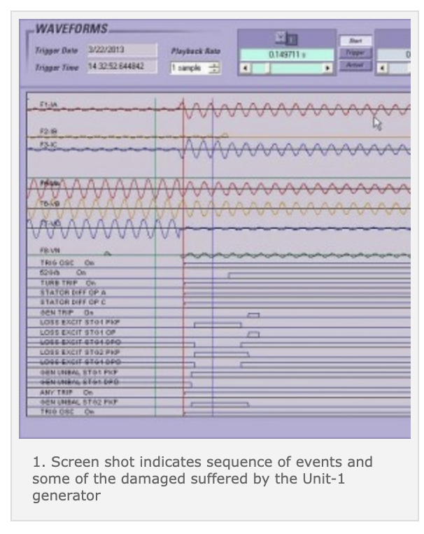
In March 2013, the user began, the 225-MVA Unit 1 generator at a 3 x 1 combined-cycle plant tripped offline. The targets on both the generator and GSU transformer relays indicated a differential current fault on phases A and C. The metering had been set to capture event data. A screen shot (Fig 1) from the event recorder shows the sequence and magnitude of the event. The observations and tests during subsequent inspection and repair confirmed what the event recorder told engineers.

This generator started commercial operation in April 2012; the plant is vital to grid voltage support in that area of the power system. With two sister units at the critical plant, the owner was highly motivated to work closely with the OEM to determine the cause of the unexpected failure and to make the best repair.
Here is the sequence of events, as indicated by the recorder and other plant alarm panels:
- 1. A half-cycle fault to ground occurred first, triggering the failure. The generator is impedence-grounded, so the initial ground-fault current was attenuated.
- 2. Within five cycles after the stator ground was indicated, a phase-to-phase (P-P) fault was identified. The differential protection activated quickly, before the ground-fault relay timed out.
- 3. There also was a change in ground-fault current indicated while the P-P currents were flowing.
- 4. The generator breaker opened about four cycles after the P-P fault started, but energy from within the generator continued to drive the fault currents in the A and C phases until the magnetic excitation collapsed. The generator’s internal energy was a big contributor to the extent of burning and loss of copper found when the machine was opened. Fault-current traces indicate total peak current into the fault area was about 60,000 amps.
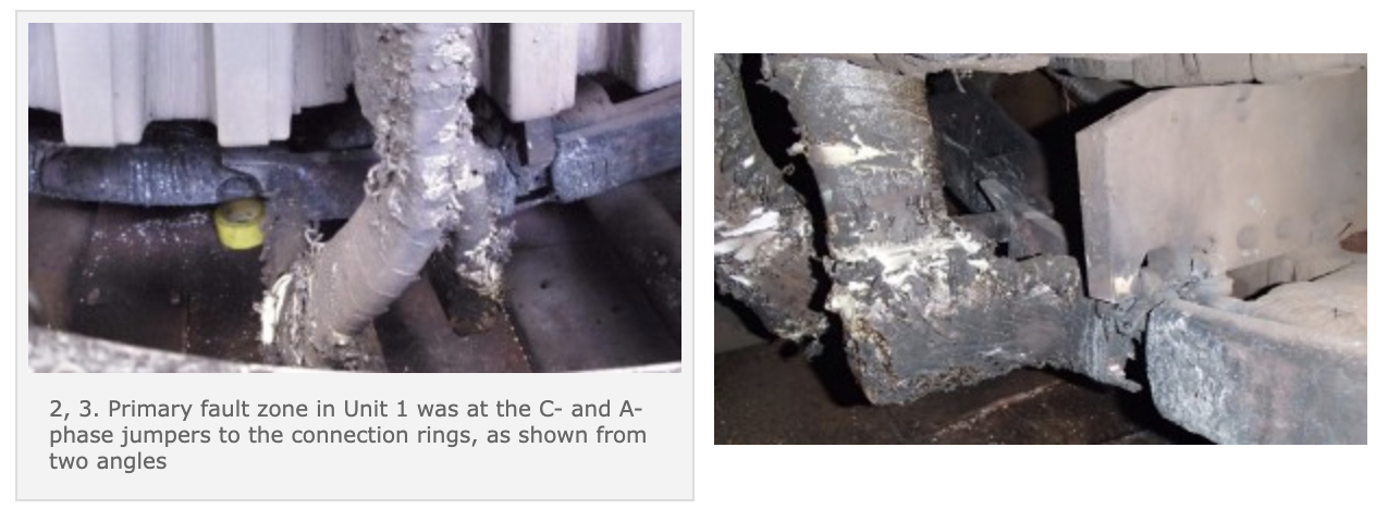
- Internal inspection indicated that the dummy ring at the 6 o’clock position had shaken loose from its glass ties to the gunstocks and had rubbed the ground wall insulation on the T3 C-phase jumper. Most of the damage was in the area where the T3 C-phase jumper is close to the T1 A-phase jumper (Figs 2, 3). Throughout the collector end of the machine there were multiple sites of tie wear and dusting to indicate movement and potential insulation damage. During the months that it took to return the unit to service, the owner and OEM examined the evidence and performed tests.

The following is a synopsis of the Unit 1 findings:
- • Felt compression was incomplete.
- • Ties were not fully filled.
- • There were gaps between tie wrap turns.
- • There was dummy-ring migration and axial support erosion in tie holes.
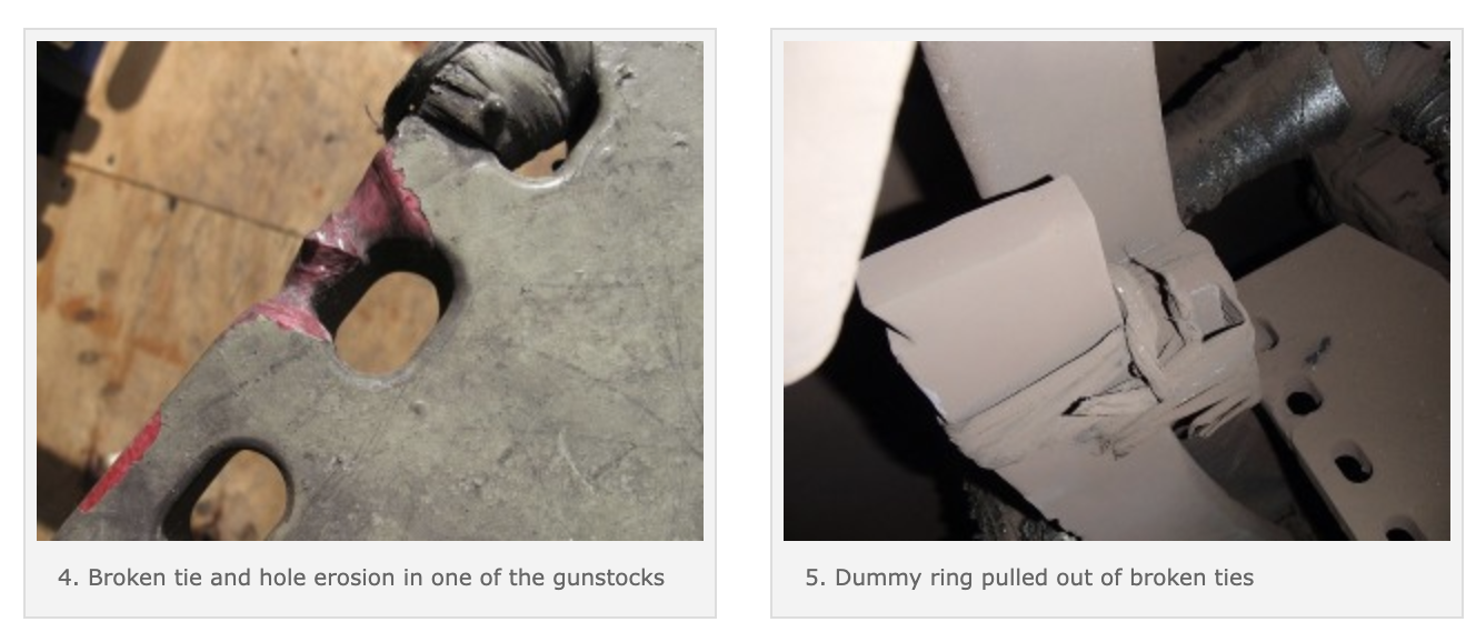
- • Broken ties were found at end-winding support arms (Fig 4).
- • An empty tie hole was found at one end-winding support arm.
The conclusion was that the unit failed because a dummy ring moved enough to make contact with a phase jumper and damage the insulation. The dummy ring moved because of insufficient bonding within the tie system (Fig 5). Failure of bonding was attributed to improper felt compression and thermal growth of the fiberglass materials during the baking/curing cycle.

The failed Unit-1 stator was completely rewound; the rotor was rewound with existing copper. A connection-ring monitoring system was installed in Unit 1 to monitor the dummy ring.
Subsequent inspection of two sister units revealed similar problems with the dry-tie system (Figs 6, 7), along with high-cycle fatigue cracks found in the carbon-steel axial support brackets of Unit 2 (Fig 8). Repairs were made to the sister units using the methods applied in the rewind of Unit 1.

Maughan’s first presentation was his industry alert on the fundamental deficiencies of protection relays installed on large generators, a problem that already has cost electric utilities half a billion dollars. Some attendees were familiar with the issue because the consultant had spoken about it at several industry meetings over the last six months and had published an article in the CCJ.
His other two presentations were tutorials—one focused on problems with newer generators, one on older generators. These certainly were of value to virtually everyone in the room. An alternative to reading through PowerPoint presentations is to listen to Maughan via CCJ ONscreen.
Moudy’s tutorial explored the key elements of outage and long-term life management of generators and covered current issues and failure modes relevant to combined-cycle units. Planning elements also were identified and discussed. You’re sure to find several of the more than 150 slides of value for in-plant training.
Trevor Foster, Calpine Corp’s electrical engineering manager, walked attendees through the ambitious two-part program his company has implemented to maintain its 635 transformers, including more than 200 generator step-up units (GSUs), at top reliability. The first part of the program is to determine and maintain the health of Calpine’s transformers through (1) electrical testing and inspection, (2) oil analysis, and (3) condition assessment. Having limited internal resources, Calpine hired Alstom Grid’s R B Watkins unit to do the first part, S D Meyer to do the second, and Doble Engineering to do the assessment.
The second part of the program is to arrange for the manufacture or lease of critical spares capable of serving multiple transformers in the event of a failure. Two failures already have occurred and spares were deployed successfully. Keep in mind that the lead-time for new transformers typically is more than a year. By mid-2013, Calpine had approximately 92% of its fleet covered by spare units and a heavy haul plan to get the transformers from their strategic storage locations to the plants that need them. CCJ


