ACCUG 2023, June 20-22
The Air-Cooled Condenser Users Group’s 2023 meeting will be held at Dominion Energy’s Innsbrook Technical Center in Glen Allen, Va, June 20-21. Thursday, June 22, is reserved for an optional tour of the utility’s Greensville County Power Station’s ACC.
Visit https://acc-usersgroup.org for meeting details, hotel suggestions, registration, etc. Questions? Contact sheila.vashi@sv-events.net.
The Air-Cooled Condenser Users Group (ACCUG) held its 13th Annual Conference, in person, at the Hilton Stamford Hotel and Executive Meeting Center in Stamford, Ct, Sept 13-15, 2022.
A few weeks earlier, ACCUG conducted its first no-cost virtual training session on some items covered at the conference (Sidebar 1).
ACCUG is the electric power industry’s only user group dedicated to discussing and resolving operation and maintenance (O&M) issues with air-cooled condensers. Annual conference topics include corrosion and chemistry, design and performance, O&M, and publishing of ACCUG Guidance Documents.
More than 50 attendees discussed these topics at the 2022 meeting, followed by a tour of the induced-draft ACC now in operation at nearby Competitive Power Ventures’ (CPV) 805-MW Towantic Energy Center, commissioned in 2018 (Sidebar 2). Andy Howell, EPRI’s technical executive for Boiler and Turbine Steam and Cycle Chemistry, chaired the event.
Below are conference highlights as a guide for the 2022 presentation materials now available here.
1. ACCUG’s first virtual training session addresses air in-leakage, corrosion, and more
The Air-Cooled Condenser Users Group held its inaugural no-cost virtual training session last July (2022)—a two-hour online event focused on air in-leakage, corrosion, and ACC performance enhancements.
Moderators/presenters were Riad Dandan (Dominion Energy), Rishi Velkar (NV Energy), Barry Dooley (Structural Integrity), and Andy Howell (EPRI).
Co-host Howell began by explaining that content was based on input, questions, concerns, and ideas raised recently through discussion forums at https://acc-usersgroup.org.
The international assembly numbered 150 participants.
CCJ participated, finding value in the technical content, Q&A, and ideas to share with its readers. The takeaways, outlined below, offer insights, verifications, new approaches to old problems, and troubleshooting experiences that can apply to nearly all powerplants.
Air in-leakage. Most air-cooled condensers operating today are large units made of thousands of finned-tube bundles acting as the heat-transfer surface to condense turbine exhaust steam (forced convection). Condensing creates a required internal vacuum, but also raises the threats of air in-leakage and dissolved oxygen in the condensate.
All ACCs, whether forced- or induced-draft, are elevated structures to allow required air flow up and over the tubes.
Large units can contain more than 20,000 tubes—that’s 40,000 tube welds with in-leakage potential. In-leakage opportunities also exist throughout ACC system components and connections.
Checking for leaks is complex, painstaking, and should be comprehensive. As one presenter clearly encouraged: “Don’t forget ground level.”
Here are a few examples of leakage potential, beyond the tubes themselves:
- Welds.
- Valves.
- Expansion joints.
- Bolts.
- Any corrosion areas.
- Rupture discs.
- Piping under insulation.
- Previously repaired leak areas.
Testing complications are many, and include factors such as:
- Size and volume of the structure.
- Height and testing access.
- Weather and winds.
- ACC fan operation during testing.
- Cost of tracer gas and restrictions on alternatives such as SF6.
Traditional detection methods and their normal frequencies and challenges were covered. Other alternatives, such as infrared (IR) scanners/cameras and acoustic leak detection, received mention.
Discussions quickly turned to the effect of in-leakage on dissolved oxygen within the system, and O2 levels considered acceptable for normal powerplant operation. Barry Dooley offered that less than 10 ppb at the condensate pump is considered normal when deaeration is part of the system, but this depends upon unit design, location, and ambient conditions.
“I have seen up to 600 ppb, which is very unusual,” he explained. “Normally, levels of 20 to 40 ppb are considered high.” Dooley added, “High oxygen levels can occur during cold start, but should soon settle unless there is leakage.”
Howell then offered a rule of thumb: “I would not advise doing a helium test unless there is a reason, such as high oxygen/carbon dioxide or abnormally high air ejection. If there is little indication of a leak, any present will be small and difficult to locate.”
Other system chemistry discussions followed, although online time was limited.
Participants were then encouraged to use the forum at https://acc-usersgroup.org for further questions and to share thoughts with other users.
Chemistry and corrosion. Dooley presented 10 slides on common chemistry concerns, most raised by participants during their registrations. Topics included common damage conditions, and the relatively new topic of film-forming substances for metal protection.
Flow-accelerated corrosion and detection methods dominated the discussions.
Performance. “Performance enhancements are always important, but become even more so in warmer weather,” explained Howell. “No ACC is big enough at 100F ambient to achieve ideal backpressure for the power cycle.”
Ideal operation is difficult to achieve, but many basic search strategies for improvement include these:
- Open doors.
- Gaps in the tubes.
- Bent fins.
- Recirculation of warmer air from perimeter cells.
- Need for tube fin cleaning.
Other improvement strategies could include:
- Spray misting.
- Adding a small condenser and wet cooling tower.
- Deluge cooling (flooding a tube row).
- Fan uprates.
- Wind screens.
Questions and concerns. The final section, led by NV Energy’s Velkar, reviewed other questions submitted by attendees. Principal topics were:
- The effects of ambient wind speed and direction.
- Wind-induced blade cracking concerns.
- Variable-speed fan experience.
- General ACC cleaning methods.
- Common gearbox issues.
CCJ’s Scott Schwieger, who coordinated and managed this two-hour event, offered a list of selected fundamental resources for the ACC community:
Ongoing forum, future events. Online discussion forums are available at https://acc-usersgroup.org/forums/ and include announcements from the group’s steering committee for upcoming events.
Technical discussions are available under these categories:
- Design.
- Fans and gearboxes.
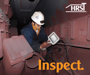
- Inspection.
- Operation and maintenance.
- Performance issues.
- Steam cycle, chemistry, and corrosion.
Future online virtual discussion sessions will be announced in CCJ and at https://acc-usersgroup.org.
Reliability
Rishi Velkar, a plant supervisor at NV Energy, gives specific examples for various reliability programs in ACC reliability improvement. Most who have visited an ACC will appreciate the elevator installed in 2016. The only follow-up costs have been annual certification and testing, and one overspeed governor replacement.
Elevators help with inspections, maintenance, carrying of supplies, walkdowns, and in one major case, a contractor life-threatening health rescue, and now are installed on all NV Energy ACCs.
Velkar discusses a master control console for fan motors, and repairs to a fan cubicle, all listed as low-cost derate avoidance. He also outlines a $1 million estimate for specific vibration, and oil pressure and temperature, monitoring equipment and upgrades. Velkar shows new cranes and concrete landing structures for gearbox replacements and drawings for a rupture-disc exchange.
He ends with a list of upcoming projects (fan motors and blades, motorized vacuum pumps, and an auxiliary boiler to hold vacuum and improve startup).
Warsaw waste-to-energy
In Poland and most of Europe, greenfield powerplants with ACCs have strict design targets being met by a new waste-to-energy unit presented by MVM EGI (Hungary). Details are provided in the PowerPoint, ACC of largest waste-to-energy plant under construction in Poland.
MVM EGI is a global cooling system provider based in Budapest; MVM Group is the largest power utility in Central and Eastern Europe.
Because waste-to-energy plants usually are located in or near cities, common benefits of this new unit include:
- Low-noise operation.
- Small visual impact.
- Small footprint.
- Zero water discharge.
- No plume.
The new unit in Warsaw (Fig 1) meets these objectives for cost-effective dry cooling and features ease of operation and maintenance. At 25 MW, the project will be the largest of its type in Poland.

The forced-draft ACC is located on the roof of the steam-turbine building (Fig 2), and wind characteristics and air flow are altered by the boiler building and high elevation. György Budik, commercial director, reviews the CFD analysis and wind-load calculations, as well as foundation and structural steel requirements.
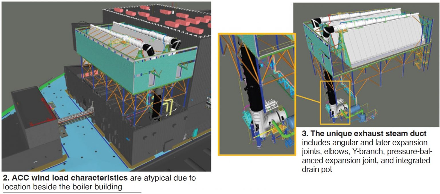
He also explains the design challenges for expansion joints and other critical components, as well as special measures taken to avoid freezing. Limited space for the exhaust steam duct called for unique solutions for expansion joints and load-bearing parts of the duct (Fig 3).
Because the plant is used for district heating in winter, evaluation of anti-freezing measures is discussed in detail.
Corrosion and chemistry
In ACC corrosion and cycle chemistry, Howell presents information provided by Barry Dooley of Structural Integrity. He launches into flow-accelerated corrosion (FAC) and its consequences, then moves to inspections using the Dooley-Howell Corrosion Index method (DHACI), followed by an update on film-forming substances.
He stresses that corrosion and chemistry issues are common worldwide, regardless of unit size or location.
DHACI has become an accepted global method for accurately measuring and monitoring corrosion in critical parts of the ACC (tube entries, cross-member supports, lower ducts, etc). The index is discussed in detail in ACC.01: Guidelines for internal inspection of air-cooled condensers, available at https://acc-usersgroup.org/reports/. It reliably indicates high iron concentrations within the cycle. Consequences can include the following:
- HRSG deposits requiring expensive chemical cleaning.
- HRSG tube failures caused by overheating, under-deposit corrosion, and hydrogen damage.
- Steam turbine deposits.
Corrosion/FAC in the ACC therefore reveals the need for iron removal processes, condensate polishing, and/or filters—also discussed in the conference.
Howell clearly states two important points:
- As explained in earlier conferences, the relationship between total iron and pH is consistent worldwide, and corrosion leads to elevated iron levels throughout the system. With the accuracy of the Dooley/Howell index, monitoring the ACC can essentially help control unit cycle chemistry.
- Evidence is global and consistent, drawn from specific operating experience in the US, Australia, Canada, Chile, China, Cote d’Ivoire, Dubai, India, Ireland, Mexico, Qatar, Abu Dhabi, South Africa, Trinidad, and the UK.
Howell moves to a brief discussion on how ACC two-phase FAC appears arrested with film-forming substances (FFS). For a review on this expanding topic, see https://www.ccj-online.com/protection-of-metal-surfaces-a-wakeup-call-on-film-forming-substances/.
He ends with a quick review of selected Technical Guidance Documents published by the International Association for the Properties of Water and Steam (www.iapws.org) with particular relevance to plants with ACCs.
Flow-accelerated condensate corrosion (FACC)
Howell then turns to his own presentation and expands with Steam cycle chemistry items in ACCs, highlighting idiosyncrasies of steam-side corrosion based on microscopic investigations that reveal some variations from typical two-phase corrosion.
Those who want the details should look here and dive into the intergranular faceted surfaces and cross-section microstructures that show what Howell calls “flow-accelerated condensate corrosion (FACC).” Microscopic observations indicate the differences.
He explains further distinguishing conditions such as operating temperatures below those optimal for single- or two-phase FAC, and an observation that under consistent conditions, metal loss may actually stop if relative stability is reached in the corrosion process.
This leads to a focused discussion on film-forming chemicals and equilibrium.
Condensate polishing
A discussion on Condensate polishing in ACCs reminds that “if properly designed, installed, maintained, and operated, polishing ensures that condensate directed towards the boiler/HRSG will be high quality and have minimal contamination.”
Although required for once-through boilers and nuclear steam generators, polishers are an option for most combined-cycle HRSGs and that decision is based on many factors. Both deep-bed and powdered-resin types are reviewed.
For air-cooled plants, the most common sources of steam-cycle contamination are air in-leakage (AIL, the primary source), makeup-water system failures, contamination of chemical treatments, poor practices in regeneration of deep-bed polisher resin, and decomposition of resins at elevated temperatures.
This presentation also discusses polishing for once-through steam generators with ACCs and hybrid-cooled (wet/dry) systems.
The conclusion: “Condensate polishing is problematic in use with ACCs and multiple factors should be evaluated to determine whether polishers are useful for a specific plant and, if installed, how to select, design, and operate polishers for optimum performance under ACC conditions.”
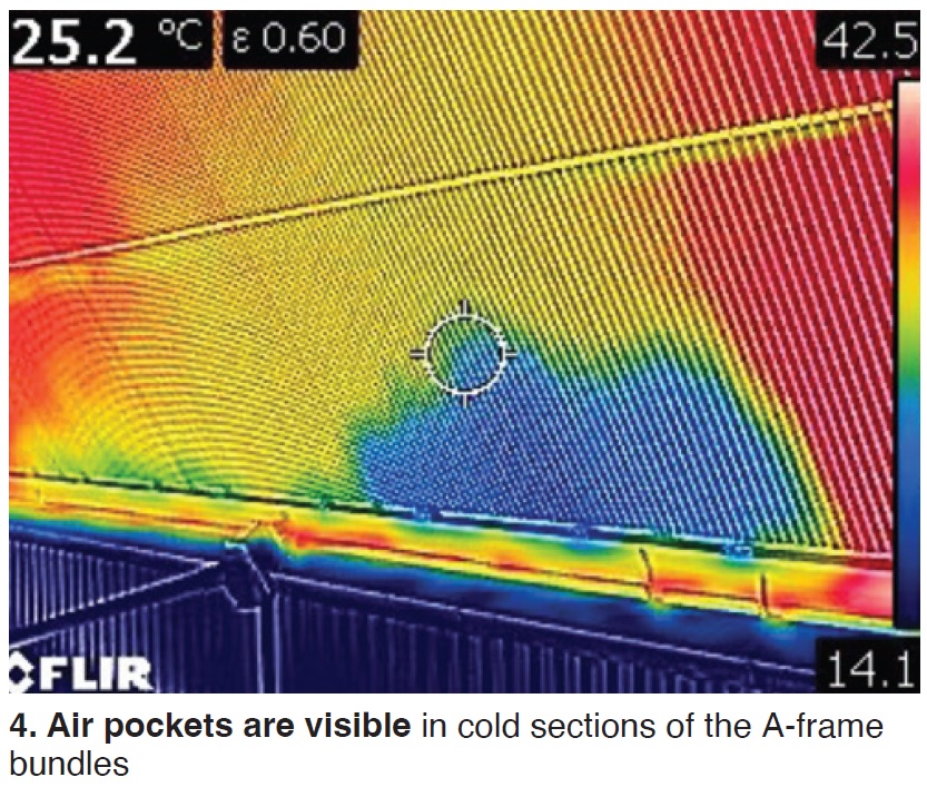 Air pockets
Evapco Dry Cooling discusses the causes, effects, and prevention of Air pockets in ACC tubes. Primary causes are backflow, vacuum system performance, excessive saturated oxygen, and excessive air ingress. Common results are reduced ACC performance and freezing risk.
In A-frame units, air pockets are visible in cold sections of the bundles (Fig 4). The presentation walks through the process where, during backflow, steam condenses but air can be left behind in pockets.
Capacity differences in the tubes are generally from air velocity or temperature differences at the face of the tube bundle. Air pockets can form in the higher capacity tubes with lower relative air temperature or higher relative air velocity.
Vacuum system performance is also an issue because vacuum is necessary and “no ACC is 100% leak tight.”
In addressing excessive saturated oxygen, the presentation covers the various deaerator types and expected O2 levels.
Air-ingress discussions include examples of leaks seen near valves and turbine shaft seals. Detailed case studies on prevention and proper ACC design close out the presentation.
Helium and options
In Alternatives to helium for AIL detection in ACCs, Howell first presents the benefits of helium tracer gas for leak detection:
- Almost always used for AIL into the vacuum created by powerplant condensers.
- Can be challenging for ACCs because of structure size, additional potential leak locations, and the effects of air currents (tracer must be applied close to point of in-leakage).
Therefore, time requirements can be extensive. Primary alternatives are infrared cameras and acoustic measurement. Coverage of the pros and cons of these alternatives is excellent.
Basics for infrared are:
- Availability and convenience.
- Easy temperature adjustments.
- Relatively rapid process.
- Good screening tool for follow-up helium testing of specific areas.
- ACC remains in operation.
Howell then reviews equipment and processes and offers some interesting tips for infrared surveys, such as recording only on the outside of fan modules and easier detection in cold weather.
For acoustics (Fig 5):
- Both audio and imaging-based results now available.
- Improvements made in background noise cancellation.
- Good screening tool for follow-up testing.
- Best when unit is offline supporting vacuum.
He again presents typical equipment and experiences.
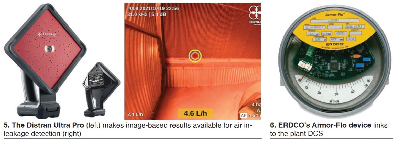
Howell ends with an ERDCO Armor-Flo® device for continuous monitoring of air exhaust flow rate, recorded on the plant DCS (Fig 6).
Gearbox
In Gearbox durability, Sumitomo Drive Technologies walks users through gearbox startup torques, sealing, and lubrication.
Kris Herijgers (Hansen Industrial Gearboxes, Belgium) presents data for both forced- and induced-draft units. He focuses on the market-driven challenge of frequent stops and starts.
Startup can lead to three times nominal torque (or higher), with an additional sinusoidal transient torque. Gear contact stresses must be kept below the endurance limit for both conditions.
With today’s cycling challenges, “Traditional American Gear Manufacturers Assn (AGMA) calculations are not sufficient,” the gear expert says. Sophisticated calculation tools are thus required that consider starting method and peak torque including the transient torque, as well as the sum of all start cycles.
He then provides details of sealing and lubrication to reduce maintenance costs.
Windscreens
In Wind effects on air-cooled condensers, Galebreaker Industrial reviews wind-screen applications to counteract wind-induced loss of thermal performance, mechanical stresses, and tube fouling.
The fundamental placement of windscreens includes:
- Perimeter screens to reduce blade stress.
- Cruciform screens for improved thermal performance.
Galebreaker covers crosswinds and performance impacts, and the dynamic impacts on blade loading and vibration. CFD analysis and example solutions follow.
Application to an innovative sloped-structure ACC is also discussed.
Fully automatic cleaning
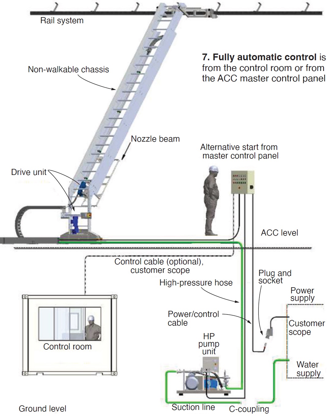 To view a fully automatic ACC cleaning and cooling system with low water use, see Fully-automated cleaning robots by JNW Cleaning Solutions GmbH, Germany.
Managing Director Arndt Krebs discusses how his company has been cleaning ACCs in Europe and South Africa since 1995, and in the US with partner Conco since 2001. Fully automatic systems have been in place since 2012.
Most semi-automatic systems operating today require two hands-on operators. The fully automatic system is centrally controlled, often from the control room (Fig 7).
Designed for and when in continuous operation, the fully automated system also becomes an ACC cooling device with these benefits:
- The cooling performance of the ACC remains high.
- Increases in backpressure are reduced significantly.
- Turbine efficiency remains high.
- Turbine throttling can be avoided.
Krebs offers plant evidence, and discusses the benefits of cooled equipment versus higher cleaning-water consumption, along with JMW’s HP-pump innovations to save water. He concludes with conversion of semi-automatic to fully-automatic systems.
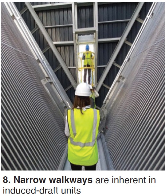 Cleaning induced-draft ACCs
AX Systems presents specifics of Cleaning induced-draft ACCs noting that these V-frame/W-style designs present some unique cleaning obstacles and all cleaning equipment must avoid collisions with obstacles in narrow walkways (Fig 8).
2. CPV shares experience with Towantic’s induced-draft ACC
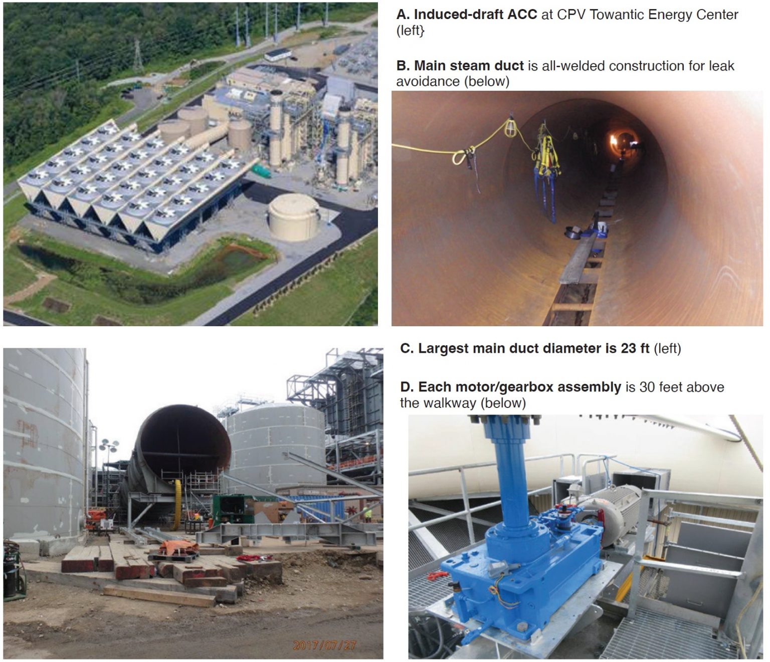
Competitive Power Ventures’ Towantic’s air-cooled condenser is a V-frame/W-style Enexio induced-draft system composed of six streets, each with five fans (Fig A). There are 18 condenser (C) sections and 12 dephlegmator (D) sections, with steam isolation on streets 1, 5, and 6.
Recognized basic advantages of induced-draft systems are reduced total ACC height (less visual impact), smaller footprint of columns, and lower initial cost over traditional forced-draft units.
CPV’s Nick Levandoski takes this further, both pros and cons:
Operationally, there is less vibration stress due to elimination of the fan bridge for possible longer life of gearboxes and fans.
He lists more operational advantages:
- Reduced auxiliary power is possible because of a lower pressure drop on the air side.
- Less hot air recirculation.
- Less sensitive to wind effects.
- Higher flexibility of sectionalizing (part-load operation) if required.
- Uniformity of air flow is improved over the face of the ACC heat exchanger tubing.
A few negatives discussed during his presentation include access from the walkway to the elevated motors and gearbox, and cleaning space limitations.
The main steam duct at Towantic is of all-welded construction for leak avoidance (Figs B and C). Length is more than 300 ft and the largest section diameter is 23 ft. Seven steam ducts then run across the top.
The steam header conveys steam to the condensing cells. Condenser tube bundles are installed below the fans. Condensing cells 1, 3, and 5 are parallel-flow tube bundles. The second and fourth cells in each row are combination modules which contain parallel condensing and counterflow D bundles. The D bundles are connected to the condenser air extraction system for removal of air and non-condensable gasses.
Expansion joints are varied:
- Single hinged.
- Tied universal.
- Dogbone.
- Single (2).
The Alex-system tube bundles are single-row, single-pass heat exchangers composed of relatively flat cross-section tubes (8 × 0.75 in.) with aluminum fins. All condensing bundles are welded together to the steam header. At the lower ends, all bundles are connected together via integrated condensate collection/steam crossover headers.
Each motor, fan brake, and Siemens/Flender right-angle gearbox is located 30 ft above the walkway (Fig D), and for that reason extra precautions are taken in preventive maintenance.
The 30, seven-blade Cofinco fans are 36 ft. across.
The as-built finned-tube cleaning system is automatic vertical and manual horizontal, with a cleaning width of 4.7 ft through 22 nozzles at 1450 psig. Flow rate is 32 gpm. It is of the no-access rolling ladder design by AX Systems.
Some issues encountered. One of biggest issues to date: A main steam-duct leak in the last expansion joint before it goes into the riser for the streets. This duct location is 23 ft diam. The expansion joint was replaced in spring 2021.
Another ongoing issue is air pockets in the D cells. Although not yet resolved, it is believed to originate upstream of the ACC. Investigation continues.
A few best practices. Gearbox seals have been an ongoing issue. Therefore, the plant began, on a semi-annual basis, to supply a filter press (water and particulate, 6 micron) to all gearboxes and run for 1.5 to 2 hours each. This, combined with oil samples prior to filter pressing, provides a good indication of oil condition for each gearbox. It also keeps the gearbox seals from failing prematurely and allows the plant to see if anything is breaking down inside.
Also, the plant installed three vibration probes on each ACC motor and three on each gearbox, running cables to a remote location. These allow the site to take vibration readings monthly on running ACC equipment, providing useful vibration data on a regular basis. The site can better understand condition of the equipment and look for alignment, coupling, and motor or gearbox bearing issues.
At CPV’s Valley Energy Center (also induced-draft), knowing the challenges and time associated with disassembly and reassembly of the fan blades and hub assembly to change out a seal, the Maintenance Dept worked to understand the failure mechanism and brought in Corrosion Products & Equipment (CPE) to collaborate on a solution. A flange-mount split seal was chosen. After a year of operation, the Inpro seal solution remains leak-free and reliable. This program will be implemented at Towantic.
For other best-practice achievements at Towantic, see https://www.ccj-online.com/?s=Towantic.
Noteworthy operating points. Condenser vacuum is pulled initially by operating both liquid-ring and maintained by collapsing of steam within the finned-tube bundles. The liquid-ring pumps remove the air and non-condensable gases from the ACC during normal operation. An air valve is provided to protect against pump cavitation.
Freeze protection is required at the site. During sub-freezing operation, ice can accumulate in the upper part of the D bundles. To remove the ice, the D fans are stopped periodically to warm the tubes. This warming function becomes active when ambient temperature is below 35.6F after a time delay of two hours. Typical D warming cycle duration is five minutes. Active warming cycle from street to street is separated by 30 minutes.
Stellenbosch research
The South African utility Eskom operates massive air-cooled condensers, and Stellenbosch University is heavily involved in both operational issues and research for improved efficiency.
In Axial-fan performance and noise modeling, members of the Dept of Mechanical and Mechatronic Engineering present detailed accounts of predicting both performance and noise in large-diameter axial-flow fans.
Those looking for a refresher on fan aerodynamic noise mechanisms can find it here with details on rotational and non-rotational noise and the dominant noise mechanisms. This includes fan numerical modeling and comparisons with experimental results.
Stellenbosch has developed the M-fan as a large-diameter (24 ft) axial-flow fan with rectangular blades, and cambers of 3.5% at the blade root and 0.8% at the tip. The design was tested in the ISO 5801 Type A fan test facility equipped to measure flow rate, pressure rise, shaft power and running speed.
Also defined are visualized numerical model results at the design flow rate.
Numerical fan noise predictions follow, breaking down the noise spectrum into components to achieve better understanding of individual noise mechanisms and how they can potentially be reduced.
Details emerge on:
- Turbulence ingestion noise.
- Tip vortex formation noise.
- Trailing edge noise.
- Total fan noise.
- Fan noise scaling and measurement.
Deep-dive details are provided. Some conclusions:
- Fan performance can be modeled accurately in a 3-D CFD virtual testing rig.
- By combining trailing-edge noise strip theory and turbulence ingestion noise models, the total fan noise spectrum can be predicted numerically with good accuracy compared to experimental measurements.
- The standard fan test facility can be used to perform comparative measurements to determine the noise characteristics of scaled fans.
The facility is now being refined to reduce self-noise during testing.
In another presentation, R&D at U of Stellenbosch, Prof Hanno Reuter defines the university’s involvement in South African ACCs, activities that have spanned five decades. Detlev Kroger initiated ACC research at Stellenbosch in the 1970s and South Africa’s large ACC designs and features are greatly influenced by this research.
Stellenbosch facilities outlined include a variety of experimental facilities with typically 50 to 70 post-graduate students per year.
Reuter includes selected current research and results from various university professors and PhD candidates, along with direct-contact details.
Published documents
Two guideline documents are currently available at https://acc-usersgroup.org/reports/:
- ACC.01: Guidelines for internal inspection of air-cooled condensers (2018 update).
- ACC.02: Guidelines for finned tube cleaning in air-cooled condensers (2021 update).
Also available are the following:
- Flow-accelerated corrosion in seam generating plants by Barry Dooley and Derek Lester, PowerPlant Chemistry 2018, 20(4).
- Corrosion in air-cooled condensers: Understanding and mitigating the mechanisms by Setsweke Phala et al, Eskom, Johannesburg, South Africa.
In-progress ACC Guidelines were discussed at the conference:
- ACC.03: Guidelines for air in-leakage in air-cooled condensers.
- ACC.04: Guidelines for wind mitigation in air-cooled condensers.
Outlines for upcoming ACC.03 and ACC.04 are available at ACC guideline documents, 2022 Annual Conference.
Question period
A 45-min discussion period at the end of the meeting focused on submitted questions dealing with wind impact on efficiency and blades, variable fan speed control, finned-tube cleaning and water collection, gearbox replacement frequency, known structural resonance issues, use of electric motors, safety protocols for blade liberation, and rupture-disc replacement strategies.