

Correcting ammonia permissive reduces emissions on startup
Challenge. Several years ago, Athens Generating received a new air permit that placed strict limits on stack emissions during startups. The plant faced significant challenges maintaining the prescribed NOx limits for cold and warm starts. Control logic at the plant dictated that the control valve for the SCR not inject ammonia until the heat-recovery steam generator (HRSG) temperature reaches 550F.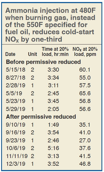
During cold and warm starts, the gas turbine (GT) typically held at around 20% load for several hours to warm up the HRSG and steam turbine (ST). The HRSG typically sat at temperatures of between 530F and 540F for hours during these starts, thereby preventing ammonia injection and keeping emissions elevated during startup.
Solution. Plant personnel reached out to the HRSG OEM and an independent contractor for input. Engineers determined the 550F permissive was based on firing the units on fuel oil. At this time, the plant only burns natural gas. Based on this information, the OEM determined the plant could safely lower the ammonia-injection permissive from 550F to 480F. The plant control logic was changed to reflect this.
Results. The lower ammonia permissive has been implemented on all three units and has been very successful in reducing NOx emissions during startup. Table presents data for a dozen cold starts on Units 1 and 2—both before and after the reduced ammonia permissive was implemented.
For the selected cold starts shown in the table, NOx emissions with the GT hovering at 20% load averaged 58.6 ppm before the change, 38.2 ppm after. This is nearly a 35% reduction in total NOx emissions when the GT is held at 20% load.
Project participants: Chris Mitchell, Todd Wolford, Bob Robinson, Hank Tripp
Emergency lighting switched from battery power to dc bus
Challenge. Emergency lighting was fed from an integral 110-V battery source. When the standard lighting loses power, emergency lighting from the 110-V battery turns on. During routine inspections of the emergency lighting system it was discovered that 10-15 light fixtures of the 80 installed were not powered. Years of heat and vibration in the turbine hall had reduced emergency-lighting battery power.
Solution. Existing fixtures were typical emergency-exit lighting with incandescent lamps. Most of these were replaced with high-efficiency LED lights. The units selected were not available with an integral battery backup. An existing system was deemed to have sufficient spare capacity to move the emergency-lighting load to the dc bus.
New inverters were manufactured and installed at the facility to pull power from the existing bus and route it to the newly installed emergency lighting fixtures. Plant staff worked with a contractor to design and implement the new system (Fig 1).
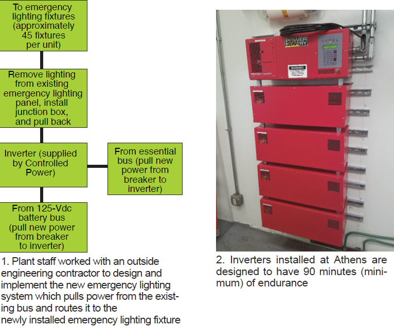
Results. The new lighting system was successfully installed in the turbine hall for all three units. The scope of the project has expanded to include the air-cooled-condenser area serving all three units as well as the water treatment plant and the river-water pump house. This is in progress on Units 2 and 3 and nearly complete on Unit 1. Because the inverters (Fig 2) power the new emergency lighting, they are always on, increasing visibility around the facility. Each inverter is designed to have at minimum 90 minutes of endurance.
Project participants: Kyle Kubler, Todd Wolford, Hank Tripp.
Stack damper improvements
Challenge. The plant’s stack damper is a fail-close design. The plant experienced several failures during gas-turbine operation, which resulted in forced outages and damage to the HRSG expansion joint. Issues related to the stack damper have caused four forced outages for the plant, with at least one being definitively linked to the stack damper closing during operation.
Solution. Plant staff researched several options. This included modification of the stack damper, replacing the stack damper, and removing the stack damper. Modifications and or replacement of the stack damper would have cost several hundred thousand dollars per unit.
The solution was to pin open the stack damper during operation. This was accomplished by adding fastening hardware to the actuating arm and linkage. When the stack damper must remain open during GT operation, the stack damper is opened and an operator inserts a pin into the slot added (Fig 3).
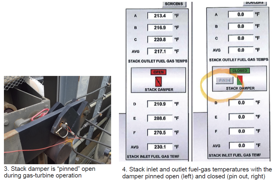
Logic was added to the control system so the control-room operator (CRO) can select a button to let him/her know that a pin is holding the stack damper open. Upon confirmation from the operator that the pin is in, the CRO selects the button to show “pin in.” To close the stack damper, an operator must first remove the pin from the stack damper and the CRO will uncheck the “pin in” button in the control system.
Results. This simple and inexpensive solution has been implemented on all three units at the plant. To date, there have been no further issues of the stack damper closing during GT operation. The DCS screen as the CRO sees it is in Fig 4.
Project participants: Rob O’Connell, Chris Mitchell, Bob Robinson, Todd Wolford, Hank Tripp

