

Planning for a major inspection in spring 2017 of the Frame 5 at a paper products plant in the Southeast was well underway Oct 10, 2016 when the unit tripped on high vibration, just as the day shift was arriving at the facility. An original Row 2 bucket failed and caused considerable downstream damage (Figs 1, 2).
The engineer responsible for the performance of major powerplant equipment at the mill huddled with management, which decided to begin necessary repairs immediately and to conduct the machine’s third major inspection at the same time.
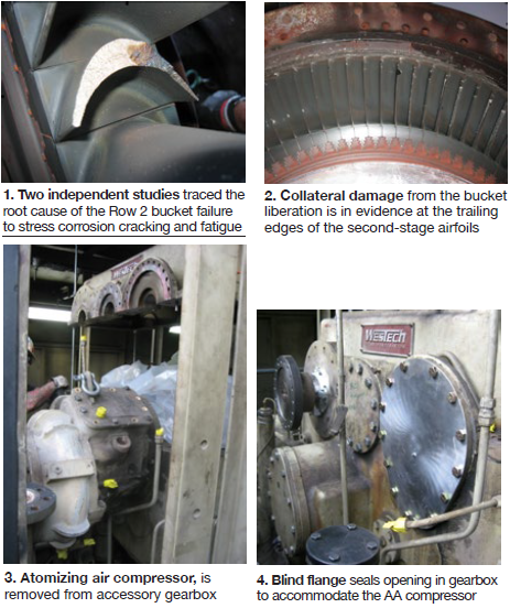
The Frame 5 cogen unit (turbine exhausts to an IST once-through steam generator) was a workhorse, having accumulated nearly 115,000 total fired hours and 1500 starts since commissioning in 1997. The GE MS5001PA engine was equipped with a DLN-1 combustion system and capable of dual-fuel firing. The 24.5-MW (gas) unit was one of the most advanced Frame 5s when installed: Only two such DLN-1 machines were operating in May 1999, according to the OEM.
Plant personnel told the editors that the bucket failure was the first major issue suffered by the engine in its lifetime. One reason for the machine’s high reliability, staff believed, is the company’s diligence in operating and maintaining the unit in accordance with OEM guidelines and industry best practices. Example: Lube-oil tests are run monthly to ensure a healthy unit.
The owner/operator did not make many significant modifications to the basic engine in its two decades of service; the 12 combustion, six hot-gas-path (HGP), and three major inspections since commissioning typically revealed little beyond normal wear and tear.
Improvements to the cogen unit over the years included retrofit of the CO2 fire protection system, and upgrades of the Mark V controls, PI historian, and compressor bleed valves. Water-cooled flame scanners were a nuisance until an additional flame scanner was added and controls were modified to require two indications for a shutdown. Plus, all control wiring was rerouted outside the package to avoid the grounds that often tripped the unit following combustion inspections.
SOS
Chris Mancini of Mechanical Dynamics & Analysis Ltd was informed of the unit trip and likely damage shortly after it occurred on Monday the tenth; MD&A had been working with the owner/operator’s team to plan the spring 2017 major. Mancini and a superintendent were onsite two days later to assist in damage assessment.
Field service personnel and their tools/parts/equipment containers arrived Thursday. On Friday, the day shift completed its site/safety orientation, organized tools and work areas, and ran power and compressed-air lines as needed. The night shift received its site orientation, set up lighting, and began unit disassembly.
The project would proceed at an aggressive pace from that point forward given the black-start cogen unit’s importance to mill production. However, safety and quality of work would not be compromised for speed. A confident owner knew the plant was prepared to handle such an emergency. Its two steam turbine/generators, bark and recovery boilers, 310,000-lb/hr standby gas-fired boiler, and electricity purchased from the local power company would satisfy process requirements. Note that with mill’s assets at full capability, the plant could open the breakers on its two tie lines with the utility and be totally self-sufficient.
MD&A was awarded a turnkey contract for repairs, the major inspections of the turbine and generator, and for some additional projects (Sidebar 1). Several specialty subcontractors were involved (Sidebar 2). As you scan the outage activities identified in Sidebar 1, keep in mind that several were far more complex than the few words used to describe them. Removal of the liquid-fuel and trip-oil systems is one of those. Likewise, outage participants identified in Sidebar 2 did not have equal responsibilities. The assignments for ACT, MD&A, and TTS were far more complex than those for the others.
Space limitations militate against meaningful coverage of all aspects of the mill’s forced outage in this article so the editors looked to the plant engineer for guidance on what he believed might be of greatest interest to the user community. He suggested these three projects:
- Removal of the liquid-fuel and trip-oil systems and the replacement of hydraulically actuated gas valves with electric valves.
- Compressor/turbine rotor inspection and repairs.
- Refurbishment of the exhaust system.
Coverage of the generator major and some other projects identified in Sidebar 1 will appear in future issues.
1. Activities completed during the Frame 5 forced outage
|
Convert to gas only. The mill never had success operating on liquid fuel. Burning of fuel nozzles and liners were two outcomes of oil combustion. The most practical solution: Don’t burn liquid fuel. This decision, made years ago by plant management, was easy given the ready availability of quality gas. Oil infrastructure remained until it ran afoul of the company’s goal of continuous improvement.
The plant engineer told the editors it took three shifts to remove liquid-fuel components to conduct a combustion inspection and three to reinstall it before engine restart. The facility has been performing CIs at 8000-hr intervals, so the cost (labor and outage schedule impact) of this activity adds up quickly. The plant engineer is guardedly optimistic about doubling that interval given the more robust coating applied by ACT on hot-section parts in its LaPorte (Tex) shop during the outage. But this requires approval by the facility’s insurer, which is currently considering the coating’s merit.
MD&A was credited with developing the plan to eliminate oil capability (including fuel-nozzle mods) at less than half the cost estimated by an alternative supplier. This portion of the overall project would not have gone forward otherwise. Bonus: Eliminating the parasitic power associated with the liquid-fuel system increases unit output by 280 kW.
Issues with fuel valves equipped with hydraulic actuators motivated the mill to replace that equipment with electrically actuated valves when the change to gas-only firing was made. A bonus for this upgrade: Less gas is burned to produce a given amount of power than with hydraulic valves in the circuit.
Replacing the mechanical overspeed bolt and trip-oil system with an electronic overspeed trip enables operators to now verify trip functionality at 500 rpm without stressing the unit.
Rotor inspection and repairs, at the heart of ACT’s capabilities, were relatively straightforward. The shop visit to fix the damage caused by the liberated second-stage bucket allowed Matt Lau and the ACT team to investigate every aspect of the rotor and upgrade all of its hardware for service up to 32k hours. Examples include oxidation-resistant coating of airfoils, hardfacing of transition pieces, and segmentation of second-stage nozzles. The last has given good results on Frame 6B and 7EA units.
The exhaust section of the unit, which did not get much attention over the years as is typical in the industry, was refurbished. Repairs and replacement seals were needed, as indicated by the 625F temperature in the load-gear area; with the unit disassembled, this was the ideal time to do the work. Temperature in the load-gear area is now in the neighborhood of 400F.
An exhaust system upgrade expected to pay dividends going forward was the installation of a hatch in the exhaust plenum to facilitate rotor removal, saving both time and money.
Today, gas-turbine performance meets expectations with one offline water wash yearly and annual change-out of filter socks (prefilters) for the primary cylindrical filters. The use of socks is a big cost saving. They are replaced quickly, economical to dispose of, and extend the life of the cylindrical filters—now at five years and counting.
Reliability is always on the plant engineer’s mind. He believes in having “two of everything” for the Frame 5 because of its importance to the mill. It certainly helped having a complete set of second-stage parts for last fall’s forced outage. He didn’t have a spared first stage which is why those components were repaired by ACT and will be replaced in the future. One of the engineer’s goals is to have a spare rotor in the plant warehouse and a second set of hardware to match.
The mark of a successful job: The unit was placed on ratchet November 27 and preoperational tests were conducted the next few days. Restart, synchronization, loading to spinning reserve occurred Thursday, December 1 without a hiccup. MD&A personnel packed up and left the site that weekend.
Converting from dual fuel to gas only
The liquid fuel system (LFS) for this Frame 5 included the following subsystems: primary and secondary liquid fuel and purge, atomizing air, and water injection and purge. LFS decommissioning, a first step in the conversion of the unit to gas-only operation included deactivation or removal of all hardware associated with oil supply as well as of equipment in the subsystems noted.
During the forced outage, key components of the LFS were removed, but because of time constraints and the physical location of some hardware, it was not feasible to remove everything at that time. Others who have performed similar conversions told the editors it’s important to disconnect/remove components that would consume power when inactive—such as the fuel pump and atomizing air compressor—and abandon in place piping that would have no adverse impact on gas-only operation.
The end covers and piping inside the turbine compartment were modified during the outage to reflect elimination of the LFS; Mark V controls software was reconfigured to accommodate the changes made.
Here’s a summary of LFS hardware removed:
- Primary liquid-fuel lines from the flow divider to the fuel nozzles.
- The accessory-gear-driven fuel pump—together with the electric clutch, coupling, bypass valve, and gear and its bearings. This task complete, a blind flange was installed to seal the pump-drive opening in the gearbox. Note that the liquid-fuel stop valve was not removed, neither was the piping from the stop valve to the fuel pump.
- The accessory-gear-driven atomizing air compressor—together with its drive gear and associated bearings. This task complete, a blind flange was installed to seal the compressor-drive opening in the gearbox (Figs 3, 4). Note that the atomizing-air filter was not removed but its inlet and outlet piping were blind-flanged.
- Extraction piping from the compressor to the atomizing- and purge-air subsystems. The extraction nozzle on the compressor shell was capped.
- Atomizing-air pre-cooler and its cooling-water supply piping. Source-air piping from the atomizing-air pre-cooler inside the turbine compartment also was removed.
- Atomizing-air booster compressor driven by the starting diesel, along with related piping and valves.
- Accessory-gearbox oil-vapor eductor; a desiccant breather cap was installed in its place.
- Gas-fuel purge system hardware.
- Water-injection piping to the fuel nozzles. Note that the water injection system for NOx control was not operational because the unit was not run on liquid fuel; however, the necessary hardware had been installed from the water-injection compartment up to the fuel nozzles.
Finally, purge-system hardware inside the gas-turbine compartment for primary and secondary liquid fuel, and water injection—including solenoid valves, purge valves, and purge-air pre-cooler—was not removed and supply piping blind-flanged.
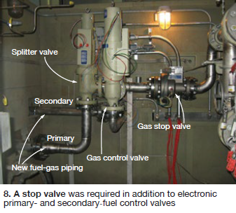
Fuel valve upgrades. The mill’s Frame 5 was equipped with a combined, hydraulically actuated gas stop speed/ratio (SRV) and control valve (GCV, Fig 5) and gas fuel splitter valve (Fig 6). Recall that the SRV and GCV are independent valves. Gas flows through the SRV to the GCV, which regulates the amount of fuel flowing to the ring manifold serving the 10 combustion chambers. The splitter valve serving on DLN machines divides gas flow between the primary and secondary fuel systems.
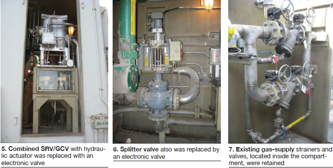
Turbine Technology Services Corp was retained to remove the liquid fuel system, as described above, and to replace the existing hydraulically actuated, 3-in. SRV/GCV and splitter valves with new electronic valves from Young & Franklin Inc. Existing gas supply strainers and valves were retained inside the compartment (Fig 7). A 3-in. stop valve was required in addition to electronic primary- and secondary-fuel control valves (Fig 8).
The company’s Dave Simmons told the editors TTS has deep experience in this work, having removed liquid-fuel capability on about 50 GE Frame 5s through EAs over the years. Plus it has retrofitted electronic valves from different suppliers on perhaps 20 machines since 1991—including a valve of its own design which is no longer offered.
Simmons said elimination of liquid-fuel capability on a non-DLN gas turbine is relatively easy, but experience counts when a DLN engine is involved. This project was unique: It was the first time to his knowledge that a Mark V-equipped DLN-1 machine was converted to electronic valves for fuel control—and it took only four weeks from initial request to startup.
TTS proved it could satisfy project goals by running tests on its reconfigured Mark V simulator. No empirical testing was involved. There were no surprises, Simmons said. The Y&F valves performed the way the company said they would.
He added that an increasing number of plants are investigating conversion to electronic valves and most projects can be justified based on opportunity costs. One of the first things to do, Simmons continued, is to determine the availability of physical space to accommodate the new equipment. This shouldn’t be challenging for non-DLN machines, he said.
Some demolition and install of the new valves and electrical conduit/wiring are key elements of the physical project. The editors were told that most wiring generally can be reused; an exception might be that for an old non-DLN unit. Note: Shielded cable is strongly recommended for use with electronic valves.
Finally, if considering electronic fuel valves for your plant, don’t forget to audit the control system logic file to see if it can accommodate the switch from hydraulics to electric. At this mill there was no such issue because so much liquid-fuel infrastructure removed.
TTS modified the gas control software in the Mark V panel and HMI operator screens and then performed functional and operational tests of the new gas control system. Other activities required to complete the project included the following:
- Disable piping to the gas control valve for the existing hydraulic- and trip-oil systems. Note that the mechanical overspeed trip was disabled when trip-oil supply to the gas control valve was terminated.
- Install two magnetic speed pickups and independently connect to the Mark V overspeed “hardware” trip.
- Install an emergency-stop pushbutton inside the accessory compartment.
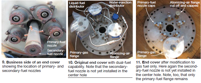
Combustion section. The Frame 5 fuel nozzles were in good condition with only light wear, according to experts. They were sent to a service shop for cleaning, flow testing, and conversion to gas only. At the same time, a set of DLN-1 end covers with refurbished primary fuel nozzles provided by the owner were converted onsite to gas only. The plant’s back-up set of secondary fuel nozzles also was converted to gas. The modified components were installed in the gas turbine (Fig 9).
To convert the dual-fuel end covers to gas only, the liquid-fuel and water-injection distributors were removed (Fig 10 before, Fig 11 after). The tubing runs connecting the distributors to the corresponding five primary-fuel nozzles on each end cover also were removed and caps installed in their place at the openings created. Secondary-fuel nozzles attach to the center of each end cover; their liquid-fuel and water-injection connections also were removed and capped.
Combustion cans, liners, crossfire tubes and retainers, transition pieces and side seals, spark plugs, and flame detectors were inspected, found in generally good condition, and most returned to service with new hardware and refurbished wear surfaces.
Rotor inspection, repairs
The GT rotor was shipped to ACT’s shop for inspection, and repairs of the compressor and turbine sections as needed. Specific tasks conducted are summarized in Sidebar 1. Rubs and minor defects identified were corrected and consumables replaced as necessary. A low-speed balance at the LaPorte facility was backed up with a high-speed balance in MD&A’s St. Louis pit.
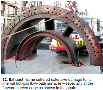
Exhaust section
The exhaust frame suffered extensive damage to its internal hot-gas flow-path surfaces—especially at the forward curved edge that exposed the aft strut cooling air to hot gas (Fig 12). The upper and lower halves of the exhaust frame assembly were moved to ACT’s service shop for repairs.
The exhaust frame was blast-cleaned in LaPorte to remove rust and corrosion. New or repaired layers of forward baffle seals were installed by the shop. The damaged second-stage aft wheelspace (discourager) seals also were repaired or replaced. The few cracks found at the support struts were weld-repaired.
Casing assembly repair work was done by ACT onsite. The No. 2 bearing housing was removed during disassembly and alignment work was performed on all the casings after reassembly.
The exhaust diffuser was removed from the unit and inspected. A crack found along the stiffener joint weld (hot gas path) was repaired by ACT onsite. A few cracks also were found inside the load-tunnel skin and were weld-repaired. All new hardware was used to marry the exhaust diffuser to the exhaust frame and the lock plates were secured.
The exhaust plenum was found corroded and in deteriorated condition both internally and externally, as most users might expect. The insulation panels had cracks and were deformed. Forward and aft flex seals were severely misaligned, allowing hot gases to escape to the turbine and load compartments. The plenum’s forward and aft flanges were deformed and the misalignment between the plenum and turbine casing was large.
The exhaust plenum was removed from the unit and sent to Industrial Metal Fabricators Inc for repairs. Fit-up to the gas turbine casing during reinstallation met expectations and new flex seals were installed forward and aft without any stress. During startup and operational tests, the turbine and load compartments remained relatively cool with little to no exhaust leakage into either.
Expansion joints between the plenum and turbine compartment, and between the plenum and load compartment, were replaced by Dekomte. Installation included reconstruction of the internal hot-gas flow path that joins the plenum to the exhaust duct and prevents exhaust gas from directly contacting the expansion-joint material. Best practice: Dekomte recommended that the exhaust duct and expansion joint be inspected for integrity during combustion inspections.
The exhaust thermocouple radiation-shield holder ring and the radiation shields were removed, inspected, and reinstalled in the exhaust plenum; the TCs were replaced, however.
Practical idea: A small cutout was made at the top forward section of the exhaust plenum to facilitate removal of the gas-turbine rotor in the future. A bolted piece made from the cutout was installed in place. CCJ
2. Principal subcontractors
|
